EP0483067A1 - Tuck-in device in a shuttleless loom - Google Patents
Tuck-in device in a shuttleless loom Download PDFInfo
- Publication number
- EP0483067A1 EP0483067A1 EP91810809A EP91810809A EP0483067A1 EP 0483067 A1 EP0483067 A1 EP 0483067A1 EP 91810809 A EP91810809 A EP 91810809A EP 91810809 A EP91810809 A EP 91810809A EP 0483067 A1 EP0483067 A1 EP 0483067A1
- Authority
- EP
- European Patent Office
- Prior art keywords
- needle
- threading
- weft
- tuck
- hole
- Prior art date
- Legal status (The legal status is an assumption and is not a legal conclusion. Google has not performed a legal analysis and makes no representation as to the accuracy of the status listed.)
- Withdrawn
Links
Images


Classifications
-
- D—TEXTILES; PAPER
- D03—WEAVING
- D03D—WOVEN FABRICS; METHODS OF WEAVING; LOOMS
- D03D47/00—Looms in which bulk supply of weft does not pass through shed, e.g. shuttleless looms, gripper shuttle looms, dummy shuttle looms
- D03D47/40—Forming selvedges
- D03D47/48—Forming selvedges by inserting cut end of weft in next shed, e.g. by tucking, by blowing
Definitions
- the present invention relates to a tuck-in device in a shuttleless loom of a type in which the leading end of a beaten-up weft yarn is tucked into a warp shed by cooperative operations of a needle which is movable reciprocally back and forth along warp yarns and also swingable reciprocally along weft yarns, of an air-operated weft holding mechanism for holding the end of a weft in ready-for-threading position, and of an air-operated threading mechanism for passing the weft end through a threading hole formed at distal end of the needle which is then swung to its threading position.
- a tuck-in device of the above type is disclosed in the Japanese Patent Application JP 61-8182.
- this conventional tuck-in device the end of a weft is held by air jet from a weft holding mechanism and the end is then passed through a threading hole of a needle, which is then moved to its threading position, by air jet from a threading mechanism.
- the needle used in this tuck-in device is bulged at its distal end portion and tapered toward its tip.
- the threading hole is formed in this needle end.
- the threading mechanism is so arranged that the axis of air jet produced by the threading mechanism is positioned laterally outward from the intersection defined by the cloth fell and the edge of tucked selvage and also spaced slightly toward a warp shed from an imaginary line defined by the cloth fell extension.
- the weft holding mechanism for catching a weft end and holding it in its ready-for-threading position is arranged such that the axis of air jet produced by the holding mechanism is positioned on an imaginary straight line extending through the above intersection and the air jet axis of the threading mechanism (which straight line extends obliquely with respect to the direction in which weft yarn extends).
- the needle end In the above arrangement of the prior art wherein the air jet axis of the threading mechanism is set as close to the cloth fell as possible, the needle end must enter a warp shed through a path which is very close to the cloth fell to bring the threading hole in the needle end in alignment with the air jet axis of the threading mechanism. This makes it difficult for the needle end to enter the warp shed smoothly.
- the position at which the needle just enters the warp shed should preferably be far enough from the cloth fell toward the warp shed.
- the needle has at its distal end a guide edge extending obliquely with respect to the extension of warp yarns in such a way that a pointed tip end of the needle formed by such oblique extension of the guide edge is spaced farthest from the cloth fell toward a warp shed when the needle is moved to its threading position, and a residual air pressure releasing hole is formed in the needle end between the above tip end and the threading hole so that the residual air pressure releasing hole is positioned substantially in alignment with the axis of air jet from the weft holding mechanism when the needle is moved to its threading position.
- a shuttleless loom as per the invention includes such a tuck-in device.
- the needle After a weft is beaten up by reed, the needle is shifted along warp yarns to bring its end just above a warp shed adjacently to the cloth fell of a woven fabric. Subsequently, the needle is swung along weft yarns to move its end into a warp shed. Before the needle end reaches its threading position, the leading end of the beaten-up weft is caught and held in its ready-for-threading position by air jet generated by the weft holding mechanism. Immediately before the needle reaches the threading position where the threading hole in the needle end is aligned with the axis of air jet from the threading mechanism, the air jet from the weft holding mechanism is stopped.
- the needle With the needle swung to the threading position, the weft end is passed through the threading hole in the needle by air jet coming from the threading mechanism. Subsequently, the needle is swung back along the weft yarns to tuck the weft end into the warp shed.
- the needle Because the needle is formed with its tip end spaced farthest from the cloth fell, the needle enters the warp shed through a position where the shed opening is relatively large. Once the tip end enters the shed, the needle can be inserted into the shed smoothly with the aid of its guide edge. In the threading position of the needle where its residual air pressure releasing hole is aligned with the axis of air jet from the weft holding mechanism, air pressure resulting from the residual air jet from the weft holding mechanism can escape through the releasing hole, with the result that weft threading will not be affected by such residual air jet.
- FIG. 1 through 7 show schematically an embodiment of the tuck-in device in a shuttleless loom and details thereof.
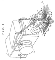
- Fig. 1 shows a tuck-in device disposed at the terminating end of weft insertion, including a cam box 1 containing therein a cam-operated drive mechanism.
- the cam box 1 has a shaft 2 and hollow shaft 3 both extending out therefrom and reciprocally movable in and out along warp yarns T.
- the hollow shaft 3 receives therein a needle shaft 4 which is reciprocally rotatable by the drive mechanism in the cam box 1 and carries at its end a needle 5.
- Rotation of the needle shaft 4 causes the needle 5 to swing about the shaft, thereby inserting the needle end into a warp shed through upper sheet of warp yarns T and moving it to a position between woven fabric W and trimmed selvage portion We .
- the needle 5 is made of a bent thin band formed at its end with a guide edge 5a extending obliquely in such a way that an acute angle is defined by and between the guide edge 5a and a lateral edge 5d2 on the side of the needle 5 remote from the cloth fell W1 so that the tip end of the needle 5 is pointed at 5e, as most clearly seen in Fig. 4 (b).
- the needle 5 is formed at its end portion with a threading hole 5b and a residual air pressure releasing hole 5c.
- the threading hole 5b is formed adjacently to the other lateral edge 5b1 of the needle 5 which is close to the cloth fell W1, while the residual air pressure releasing hole 5c is formed between the tip end 5e and the threading hole 5b.
- a mounting 6 having a depending portion 6a to which a holding block 7 is fastened.
- Two nozzle blocks 8, 9 are mounted one above the other on the front surface of the holding block 7.
- the upper nozzle block 8 has threading air jet nozzle 8a opening at the bottom thereof, while the lower nozzle block 9 has an air jet reception hole 9a bored therethrough in alignment with the opening of the threading air jet nozzle 8a.
- the lower nozzle block 9 has a weft holding air jet nozzle 9b opening at the top thereof, while the upper nozzle block 8 has and air jet reception hole 8b bored therethrough in alignment with the opening of the weft holding air jet nozzle 9b.
- a positioning bracket 10 is fixed to the top of the mounting 6 on the side of the hollow shaft 3 and a stop bolt 11 is screwed at the distal end of the bracket 10.
- the stop bolt 11 is contactable with a bolt 12 which secures the needle 5 on the needle shaft 4.
- swinging of the needle 5 can be stopped by contact engagement between the bolt 12 and the stop bolt 11 at a position where the threading hole 5b of the needle 5 is located between and in alignment with the threading nozzle 8a and its associated reception hole 9a.
- a pair of knife blades 13A, 13B is rotatably supported by a support shaft 14 at a lateral side of lower portion of the holding block 7.
- the knife blades 13A, 13B have guide pins 13a, 13b projecting therefrom and engaging with guide slits 15a, 15b, respectively, which are formed in a guide plate 15 depending from the bottom of the cam box 1.
- the knife blades 13A, 13B are movable along the guide slits 15a, 15b back and forth together with the shaft 2 and hollow shaft 3, and such movement of the guide pins 13a, 13b along the guide slits 15a, 15b causes the knife blades 13A, 13B to make a cutting motion.
- the leading end of an inserted weft Y reaching the terminating end of weft insertion is cut by the knife blades 13A, 13B actuated to make such cutting motion.
- a mechanical rotary valve mechanism 16 which is driven to operate by the cam-operated drive mechanism in the cam box 1.
- the threading air jet nozzle 8a and the weft holding air jet nozzle 9b are connected to the rotary valve mechanism 16 by way of tubes 17, 18, respectively, and air injection from the nozzles 8a and 9b is controlled by the rotary valve mechanism 16.
- the curved lines C1 and C2 represent air injection pressures of the weft holding air jet nozzle 9b and threading air jet nozzle 8a for the angle of rotation (0) of the weaving loom, respectively.
- the needle 5 When entering a warp shed, the needle 5 goes into the shed with its tip end 5e entering thereinto first. Once the tip end 5e has entered into the shed, the entire needle 5 can be inserted smoothly with the aid of its guide edge 5a. Because the needle tip end 5e which enters the shed first is spaced far enough from the cloth fell W1, initial penetration of the tip end into the warp shed can be performed with ease. As is now evident, the purpose of forming the needle 5 in the shape of a bent band is to space the needle tip end 5e as far from the cloth fell W1 as possible.
- the threading hole 5b can be brought into proper alignment with the axis l1 of air jet coming from the threading nozzle 8a merely by swinging the needle 5 along weft yarns W, as well as insertion of the needle 5 into a warp shed can be performed easily.
- the threading hole 5b encircles the air injection region of the threading air jet nozzle 8a as viewed along the axis l1 of air jet from the nozzle 8a, and the residual air pressure releasing hole 5c also covers the air injection region of the weft holding nozzle 9b as seen along the axis l2 of air jet from the nozzle 9b.
- the respective air jet axes l1, l2 of the threading and weft holding air jet nozzles 8a, 9b lie on a straigth line L (shown in Fig.
- the straigth line L represents the ready-for-threading position in which the end of weft Y is held in the reception hole 8b by air jet from the weft holding nozzle 9b.
- Fig. 3 shows a condition of the tuck-in device before the angle 01 is reached, where the end of the weft Y cut by the knife blades 13A, 13B is held in the reception hole 8b by the action of air jet from the weft holding nozzle 9b.
- Fig. 4 (a) and (b) shows a condition of the tuck-in device over the range of angle of rotation (02, 03) in which the threading hole 5b is placed in alignment with the axis l1 of air jet from the threading nozzle 8a. If the needle 5 were not provided at its end with the residual air pressure releasing hole 5c, air jet injected by the weft holding nozzle 9b would impinge against the needle 5 to be diffused in the vicinities.
- the angle of rotation of the loom at the point E which is defined by the intersection of the two curved lines C1 and C2 in Fig. 5, requires must be adjusted. That is, shifting of condition from weft holding in the reception hole 8b to weft passing through the threading hole 5b should preferably commence approximately at an intermediate point between 01 and E. This adjustment is very delicate and hence troublesome.
- the adjustment for the point E is easy in the above-described embodiment according to the invention because the point E may be established anywhere while the threading hole 5b encircles the air injection region of the threading air jet nozzle 8a. Furthermore, if the needle 5 were not provided with the hole 5c, it would be necessary to make readjustment for the point E for each different count of weft yarn to be handled. According to the present invention, however, no such readjustment is required. Additionally, if it were not for the residual air pressure releasing hole 5c, air injection pressure will greatly influence the success in threading and, therefore, adjustment of the air injection pressure would be required. In the present invention, however, adjustment of air injection pressure may be just roughly made.
- the needle 5 is formed at its end corresponding to the air injection region of the weft holding nozzle 9a with a residual air pressure releasing recess 5f.
- the tip end 5e of the needle 5 is spaced farthest from the cloth fell W1, as in the first embodiment, to facilitate the insertion of the needle 5 into a warp shed and help to achieve successful threading.
- the needle 5 is formed with a single triangular opening 5g which performs double function of the threading hole 5b and the residual air pressure releasing hole 5c in the previously described embodiments. It is noted that the triangle of the opening 5g is so shaped that an acute-angled apex portion 5g1 is positioned between the lateral edge 5d1 adjacent to the cloth fell and the guide edge 5a. This helps to tuck the weft end into a warp shed smoothly.
- the needle has at its end a guide edge extending obliquely in such a way that a pointed tip end of the needle formed by such oblique extension of the guide edge is spaced farthest from the cloth fell toward a warp shed when the needle is moved to its threading position, and a residual air pressure releasing hole formed in the needle end between the above tip end and the threading hole, it can offer advantages that the needle 5 can be inserted into the shed firstly with its tip end which is spaced farthest from the cloth fell, that the needle can be brought to its threading position in a warp shed merely by a single swinging motion of the needle thereby making possible improvement in operating speed of the tuck-in device, and also that harmful influence of residual air jet on the weft end, hence on the success in threading, can be prevented.
- Fig. 1 is a perspective view showing a tuck-in device provided at the terminating end of weft insertion:
- Fig. 2 is a longitudinal cross-sectional view showing part of the tuck-in device;
- Fig. 3 (a) is a longitudinal cross-sectional view showing a condition of the tuck-in device in which a weft end is held;
- Fig. 3 (b) is a cross-sectional view taken along line A-A of Fig. 3 (a);
- Fig. 4 (a) is a longitudinal cross-sectional view showing a condition of the tuck-in device in which the needle has been threaded;
- Fig. 4 (b) is a cross-sectional view taken along line B-B of Fig.
- Fig. 5 is a diagram showing air injection pressure curves of the threading and weft holding nozzles, respectively;
- Figs. 6 and 7 are plan views showing part of the tuck-in devices in modified embodiments, respectively, according to the present invention.
- the tuck-in device in the shuttle includes a tuck-in needle 5 that swings reciprocally across warp yarns T.
- the end of the weft yarn Y is held by an air-operated weft holding mechanism 8, 8b, 9, 9b, 18 in an ready-for-threading position.
- an air-operated weft threading mechanism 8, 8a, 9, 9a, 17 transfers the end of the weft thread Y to the threading hole 5b of the needle 5.
- the holding and the threading mechanism does each include either a suction or a blowing jet nozzle 17, 18.
- the tuck-in needle 5 includes further a guide edge 5a that extends obliquely with respect to the direction of the warp yarn T therebye forming a pointed tip end 5e.
- the needle 5 is mount in a way that its tip end 5e is spaced farthest from the cloth fell W1 when the needle 5 is moved into the threading position.
- Needle 5 Needle 5; Guide edge 5a; Threading hole 5b; Residual pressure releasing hole 5c; Needle tip end 5e; Air jet type threading mechanism including threading nozzle 8a and its associated air jet reception hole 9a; Air jet type weft holding mechanism including weft holding nozzle 9b and its associated air jet reception hole 8b; Axes or all jets l1, l2.
Abstract
The tuck-in device in the shuttle includes a tuck-in needle (5) that swings reciprocally across warp yarns (T). The end of the weft yarn (Y) is held by an air-operated weft holding mechanism (8, 8b, 9, 9b, 18) in an ready-for-threading position. When the tuck-in needle (5) is in the threading position an air-operated weft threading mechanism (8, 8a, 9, 9a, 17) transfers the end of the weft thread (Y) to the threading hole (5b) of the needle (5). The holding and the threading mechanism does each include either a suction or a blowing jet nozzle (17, 18). The tuck-in needle (5) includes further a guide edge (5a) that extends obliquely with respect to the direction of the warp yarn (T) therebye forming a pointed tip end (5e). The needle (5) is mount in a way that its tip end (5e) is spaced farthest from the cloth fell (W₁) when the needle (5) is moved into the threading position.
Description
- The present invention relates to a tuck-in device in a shuttleless loom of a type in which the leading end of a beaten-up weft yarn is tucked into a warp shed by cooperative operations of a needle which is movable reciprocally back and forth along warp yarns and also swingable reciprocally along weft yarns, of an air-operated weft holding mechanism for holding the end of a weft in ready-for-threading position, and of an air-operated threading mechanism for passing the weft end through a threading hole formed at distal end of the needle which is then swung to its threading position.
- A tuck-in device of the above type is disclosed in the Japanese Patent Application JP 61-8182. According to this conventional tuck-in device, the end of a weft is held by air jet from a weft holding mechanism and the end is then passed through a threading hole of a needle, which is then moved to its threading position, by air jet from a threading mechanism. The needle used in this tuck-in device is bulged at its distal end portion and tapered toward its tip. The threading hole is formed in this needle end.
- For forming good selvage in weaving, it is necessary that the threading hole at the needle end should be as close to the cloth fell of woven fabric as possible when the needle is moved to its threading position. For this reason, the threading mechanism is so arranged that the axis of air jet produced by the threading mechanism is positioned laterally outward from the intersection defined by the cloth fell and the edge of tucked selvage and also spaced slightly toward a warp shed from an imaginary line defined by the cloth fell extension. On the other hand, the weft holding mechanism for catching a weft end and holding it in its ready-for-threading position is arranged such that the axis of air jet produced by the holding mechanism is positioned on an imaginary straight line extending through the above intersection and the air jet axis of the threading mechanism (which straight line extends obliquely with respect to the direction in which weft yarn extends).
- In the above arrangement of the prior art wherein the air jet axis of the threading mechanism is set as close to the cloth fell as possible, the needle end must enter a warp shed through a path which is very close to the cloth fell to bring the threading hole in the needle end in alignment with the air jet axis of the threading mechanism. This makes it difficult for the needle end to enter the warp shed smoothly. For achieving smoothness in inserting the needle end into a shed through warp yarns, the position at which the needle just enters the warp shed should preferably be far enough from the cloth fell toward the warp shed. If the needle end is inserted through such a position, however, the needle end must be shifted toward the cloth fell after the needle insertion to align the threading hole in the needle with the air jet axis of the threading mechanism. Such additional shifting movement of the needle will inevitably complicate a needle drive mechanism. Additionally, such needle movement is obviously disadvantageous to achieve high-speed operation of the weaving loom.
- Accordingly, it is an object of the present invention to provide an air-operated tuck-in device which permits smooth entry of the needle end into a warp shed without restricting the operating speed of the loom.
- According to the present invention, the needle has at its distal end a guide edge extending obliquely with respect to the extension of warp yarns in such a way that a pointed tip end of the needle formed by such oblique extension of the guide edge is spaced farthest from the cloth fell toward a warp shed when the needle is moved to its threading position, and a residual air pressure releasing hole is formed in the needle end between the above tip end and the threading hole so that the residual air pressure releasing hole is positioned substantially in alignment with the axis of air jet from the weft holding mechanism when the needle is moved to its threading position. A shuttleless loom as per the invention includes such a tuck-in device.
- After a weft is beaten up by reed, the needle is shifted along warp yarns to bring its end just above a warp shed adjacently to the cloth fell of a woven fabric. Subsequently, the needle is swung along weft yarns to move its end into a warp shed. Before the needle end reaches its threading position, the leading end of the beaten-up weft is caught and held in its ready-for-threading position by air jet generated by the weft holding mechanism. Immediately before the needle reaches the threading position where the threading hole in the needle end is aligned with the axis of air jet from the threading mechanism, the air jet from the weft holding mechanism is stopped. With the needle swung to the threading position, the weft end is passed through the threading hole in the needle by air jet coming from the threading mechanism. Subsequently, the needle is swung back along the weft yarns to tuck the weft end into the warp shed.
- Because the needle is formed with its tip end spaced farthest from the cloth fell, the needle enters the warp shed through a position where the shed opening is relatively large. Once the tip end enters the shed, the needle can be inserted into the shed smoothly with the aid of its guide edge. In the threading position of the needle where its residual air pressure releasing hole is aligned with the axis of air jet from the weft holding mechanism, air pressure resulting from the residual air jet from the weft holding mechanism can escape through the releasing hole, with the result that weft threading will not be affected by such residual air jet.
- The following will describe an embodiment according to the present invention with reference to the accompanying drawings. Fig. 1 through 7 show schematically an embodiment of the tuck-in device in a shuttleless loom and details thereof.
- The drawings show the following:
- Fig. 1 is a perspective view showing a tuck-in device provided at the terminating end of weft insertion;
- Fig. 2 is a longitudinal cross-sectional view showing part of the tuck-in device;
- Fig. 3 (a) is a longitudinal cross-sectional view showing a condition of the tuck-in device in which a weft end is held;
- Fig. 3 (b) is a cross-sectional view taken along line A-A of Fig. 3 (a);
- Fig. 4 (a) is a longitudinal cross-sectional view showing a condition of the tuck-in device in which the needle has been threaded;
- Fig. 4 (b) is a cross-sectional view taken along line B-B of Fig. 4 (a);
- Fig. 5 is a diagram showing air injection pressure curves of the threading and weft holding nozzles, respectively;
- Figs. 6 and 7 respectively are plan views, showing part of the tuck-in devices, according to the present invention in modified embodiments.
- Fig. 1 shows a tuck-in device disposed at the terminating end of weft insertion, including a cam box 1 containing therein a cam-operated drive mechanism. The cam box 1 has a
shaft 2 andhollow shaft 3 both extending out therefrom and reciprocally movable in and out along warp yarns T. Thehollow shaft 3 receives therein a needle shaft 4 which is reciprocally rotatable by the drive mechanism in the cam box 1 and carries at its end aneedle 5. Rotation of the needle shaft 4 causes theneedle 5 to swing about the shaft, thereby inserting the needle end into a warp shed through upper sheet of warp yarns T and moving it to a position between woven fabric W and trimmed selvage portion We. - The
needle 5 is made of a bent thin band formed at its end with aguide edge 5a extending obliquely in such a way that an acute angle is defined by and between theguide edge 5a and a lateral edge 5d₂ on the side of theneedle 5 remote from the cloth fell W1 so that the tip end of theneedle 5 is pointed at 5e, as most clearly seen in Fig. 4 (b). Theneedle 5 is formed at its end portion with athreading hole 5b and a residual airpressure releasing hole 5c. Thethreading hole 5b is formed adjacently to the other lateral edge 5b₁ of theneedle 5 which is close to the cloth fell W1, while the residual airpressure releasing hole 5c is formed between thetip end 5e and thethreading hole 5b. Between the projecting ends of theshaft 2 andhollow shaft 3 is fixed a mounting 6 having a depending portion 6a to which a holding block 7 is fastened. Twonozzle blocks upper nozzle block 8 has threadingair jet nozzle 8a opening at the bottom thereof, while thelower nozzle block 9 has an airjet reception hole 9a bored therethrough in alignment with the opening of the threadingair jet nozzle 8a. On the other hand, thelower nozzle block 9 has a weft holdingair jet nozzle 9b opening at the top thereof, while theupper nozzle block 8 has and airjet reception hole 8b bored therethrough in alignment with the opening of the weft holdingair jet nozzle 9b. - A
positioning bracket 10 is fixed to the top of the mounting 6 on the side of thehollow shaft 3 and astop bolt 11 is screwed at the distal end of thebracket 10. Thestop bolt 11 is contactable with abolt 12 which secures theneedle 5 on the needle shaft 4. Thus, swinging of theneedle 5 can be stopped by contact engagement between thebolt 12 and thestop bolt 11 at a position where thethreading hole 5b of theneedle 5 is located between and in alignment with thethreading nozzle 8a and its associatedreception hole 9a. - A pair of
knife blades support shaft 14 at a lateral side of lower portion of the holding block 7. Theknife blades guide pins guide slits 15a, 15b, respectively, which are formed in aguide plate 15 depending from the bottom of the cam box 1. Theknife blades guide slits 15a, 15b back and forth together with theshaft 2 andhollow shaft 3, and such movement of theguide pins guide slits 15a, 15b causes theknife blades knife blades - On a lateral side of the cam box 1 is mounted a mechanical
rotary valve mechanism 16 which is driven to operate by the cam-operated drive mechanism in the cam box 1. The threadingair jet nozzle 8a and the weft holdingair jet nozzle 9b are connected to therotary valve mechanism 16 by way oftubes nozzles rotary valve mechanism 16. Referring to Fig. 5, the curved lines C1 and C2 represent air injection pressures of the weft holdingair jet nozzle 9b and threadingair jet nozzle 8a for the angle of rotation (0) of the weaving loom, respectively. - When entering a warp shed, the
needle 5 goes into the shed with itstip end 5e entering thereinto first. Once thetip end 5e has entered into the shed, theentire needle 5 can be inserted smoothly with the aid of itsguide edge 5a. Because theneedle tip end 5e which enters the shed first is spaced far enough from the cloth fell W1, initial penetration of the tip end into the warp shed can be performed with ease. As is now evident, the purpose of forming theneedle 5 in the shape of a bent band is to space theneedle tip end 5e as far from the cloth fell W1 as possible. By thus forming theneedle 5, thethreading hole 5b can be brought into proper alignment with the axis l1 of air jet coming from the threadingnozzle 8a merely by swinging theneedle 5 along weft yarns W, as well as insertion of theneedle 5 into a warp shed can be performed easily. - With the needle moved to its threading position as shown in Fig. 4, the
threading hole 5b encircles the air injection region of the threadingair jet nozzle 8a as viewed along the axis l1 of air jet from thenozzle 8a, and the residual airpressure releasing hole 5c also covers the air injection region of theweft holding nozzle 9b as seen along the axis l2 of air jet from thenozzle 9b. The respective air jet axes l1, l2 of the threading and weft holdingair jet nozzles reception hole 8b by air jet from theweft holding nozzle 9b. - As indicated by the curved lines C1, C2 in Fig. 5, when the angle of
rotation 01 is reached by the loom, theweft holding nozzle 9b stops its air injection while the threadingnozzle 8a commences its air injection. Fig. 3 (a) and (b) shows a condition of the tuck-in device before theangle 01 is reached, where the end of the weft Y cut by theknife blades reception hole 8b by the action of air jet from theweft holding nozzle 9b. - Fig. 4 (a) and (b) shows a condition of the tuck-in device over the range of angle of rotation (02, 03) in which the
threading hole 5b is placed in alignment with the axis l1 of air jet from the threadingnozzle 8a. If theneedle 5 were not provided at its end with the residual airpressure releasing hole 5c, air jet injected by theweft holding nozzle 9b would impinge against theneedle 5 to be diffused in the vicinities. - The end of the weft Y held in the
reception hole 8b is blown through thethreading hole 5b and then into thereception hole 9a by air jet from the threadingair jet nozzle 8a, as shown in Fig. 4 (a) and (b). Upon such threading, the needle shaft 4 is swung back to move the end of theneedle 5 out of the warp shed and thehollow shaft 3 is shifted back to retract theneedle 5 toward the cloth fell W1. - Passing of the weft end through the
threading hole 5b of theneedle 5 takes place at an angle of rotation of the loom corresponding approximately to the air injection pressure peak on the curved line C2 in Fig. 5. If the end of the weft Y then fails to lie properly in the ready-for-threading position L, it may result in failure in threading. As understood from the curved line C1, though air injection from theweft holding nozzle 9b is stopped at 01, residual air injection follows even after that angle of rotation. Though such residual air injection continues even when the needle end is moved to its threading position, air pressure due to the residual air injection is released through thehole 5c and escapes upwards above theneedle 5. Thus, there is no fear that the residual air jet impinges against the end of theneedle 5 to be diffused in the vicinities. The end portion of the weft Y can be held properly in its ready-for-threading position L without being influenced by the residual air injection and, therefore, the weft end held in thereception hole 9a can be subjected only to the air jet from the threadingnozzle 8a. The result is that threading, or passing the weft end through thethreading hole 5b, is carried out successfully and good tucked selvage is formed accordingly. - If the
needle 5 were not formed with a hole such as the residual airpressure releasing hole 5c, the air injection region of theweft holding nozzle 9b would be blocked by the end of theneedle 5 when it is moved to the threading position. To avoid the influence of the residual air pressure due to continued residual air jet injection, the angle of rotation of the loom at the point E, which is defined by the intersection of the two curved lines C1 and C2 in Fig. 5, requires must be adjusted. That is, shifting of condition from weft holding in thereception hole 8b to weft passing through thethreading hole 5b should preferably commence approximately at an intermediate point between 01 and E. This adjustment is very delicate and hence troublesome. Contrary thereto, the adjustment for the point E is easy in the above-described embodiment according to the invention because the point E may be established anywhere while thethreading hole 5b encircles the air injection region of the threadingair jet nozzle 8a. Furthermore, if theneedle 5 were not provided with thehole 5c, it would be necessary to make readjustment for the point E for each different count of weft yarn to be handled. According to the present invention, however, no such readjustment is required. Additionally, if it were not for the residual airpressure releasing hole 5c, air injection pressure will greatly influence the success in threading and, therefore, adjustment of the air injection pressure would be required. In the present invention, however, adjustment of air injection pressure may be just roughly made. - It is to be understood that the present invention is not limited to the above-described embodiment, but practiced in other various forms, as exemplified in Figs. 6 and 7.
- Referring to the modified embodiment shown in Fig. 6, the
needle 5 is formed at its end corresponding to the air injection region of theweft holding nozzle 9a with a residual air pressure releasing recess 5f. In this embodiment, thetip end 5e of theneedle 5 is spaced farthest from the cloth fell W1, as in the first embodiment, to facilitate the insertion of theneedle 5 into a warp shed and help to achieve successful threading. - Referring then to Fig. 7, the
needle 5 is formed with a singletriangular opening 5g which performs double function of thethreading hole 5b and the residual airpressure releasing hole 5c in the previously described embodiments. It is noted that the triangle of theopening 5g is so shaped that an acute-angled apex portion 5g₁ is positioned between the lateral edge 5d₁ adjacent to the cloth fell and theguide edge 5a. This helps to tuck the weft end into a warp shed smoothly. - As it would be now obvious from the foregoing description, in the tuck-in device according to the present invention, wherein the needle has at its end a guide edge extending obliquely in such a way that a pointed tip end of the needle formed by such oblique extension of the guide edge is spaced farthest from the cloth fell toward a warp shed when the needle is moved to its threading position, and a residual air pressure releasing hole formed in the needle end between the above tip end and the threading hole, it can offer advantages that the
needle 5 can be inserted into the shed firstly with its tip end which is spaced farthest from the cloth fell, that the needle can be brought to its threading position in a warp shed merely by a single swinging motion of the needle thereby making possible improvement in operating speed of the tuck-in device, and also that harmful influence of residual air jet on the weft end, hence on the success in threading, can be prevented. - Fig. 1 is a perspective view showing a tuck-in device provided at the terminating end of weft insertion: Fig. 2 is a longitudinal cross-sectional view showing part of the tuck-in device; Fig. 3 (a) is a longitudinal cross-sectional view showing a condition of the tuck-in device in which a weft end is held; Fig. 3 (b) is a cross-sectional view taken along line A-A of Fig. 3 (a); Fig. 4 (a) is a longitudinal cross-sectional view showing a condition of the tuck-in device in which the needle has been threaded; Fig. 4 (b) is a cross-sectional view taken along line B-B of Fig. 4 (a); Fig. 5 is a diagram showing air injection pressure curves of the threading and weft holding nozzles, respectively; Figs. 6 and 7 are plan views showing part of the tuck-in devices in modified embodiments, respectively, according to the present invention.
- The tuck-in device in the shuttle includes a tuck-in
needle 5 that swings reciprocally across warp yarns T. The end of the weft yarn Y is held by an air-operatedweft holding mechanism needle 5 is in the threading position an air-operatedweft threading mechanism threading hole 5b of theneedle 5. The holding and the threading mechanism does each include either a suction or a blowingjet nozzle needle 5 includes further aguide edge 5a that extends obliquely with respect to the direction of the warp yarn T therebye forming apointed tip end 5e. Theneedle 5 is mount in a way that itstip end 5e is spaced farthest from the cloth fell W₁ when theneedle 5 is moved into the threading position. -
Needle 5;Guide edge 5a;Threading hole 5b; Residualpressure releasing hole 5c;Needle tip end 5e; Air jet type threading mechanism including threadingnozzle 8a and its associated airjet reception hole 9a; Air jet type weft holding mechanism includingweft holding nozzle 9b and its associated airjet reception hole 8b; Axes or all jets l1, l2.
Claims (7)
- A tuck-in device in a shuttleless loom in which weft tucking is effected by cooperative operations of a needle (5) which is movable reciprocally back and forth across warp yarns (T) and swingable reciprocally across weft yarns (Y) held by an air-operated weft holding mechanism (8, 8b, 9, 9b, 18) for laying and holding the end of a weft (Y) in ready-for-threading position, and of an air-operated threading mechanism (8, 8a, 9, 9a, 17) for passing the weft end through a threading hole (5b) formed at the distal end of said needle (5) which is then swung to its threading position, where said threading hole (5b) is positioned substantially in alignment with the axis of air jet (17) from said air-operated threading mechanism, said needle comprising further at its distal end a guide edge (5a), extending obliquely with respect to said extension of warp yarns (Y) in such a way, that a pointed tip end (5e) of said needle (5) formed by the oblique extension (5a) of said guide edge is spaced farthest from the cloth fell (W₁) toward the warp shed when the needle (5) is swung to said threading position, and said needle (5) further comprising a residual air pressure releasing hole (5c) formed therethrough and beeing placed between said tip end (5e) and said threading hole (5b) and positioned substantially in alignment with the axis of air jet (18) of said weft holding mechanism when said needle (5) is swung to said threading position.
- A tuck-in device as claimed in claim 1 wherein said residual air pressure releasing hole in the needle (5) is a recess (5, 5f in Fig. 6)
- A tuck-in device as claimed in claim 1 wherein said residual air pressure releasing hole an said threading hole are interconnected by an opening so that they are part of a larger hole that includes the area of the two said holes and an interconnecting area (5, 5g in Fig. 7).
- A tuck-in device as claimed in any of claims 1 to 3 further comprising means for moving said needle (5) forth and back towards the cloth fell when said needle is tucking-in the threaded warp yarn (Y).
- A tuck-in device as claimed in any of claims 1 to 4, wherein said air operated threading mechanism does include at least one suction nozzle.
- A tuck-in device in a shuttleless loom in which weft tucking is effected by cooperative operations of a needle which is movable reciprocally back and forth along warp yarns and also swingable reciprocally along weft yarns, of an air-operated weft holding mechanism for laying and holding the end of a weft in ready-for-threading position, arid of an air-operated threading mechanism for passing the weft end through a threading hole formed at distal end of said needle which is then swung to its threading position where said threading hole is positioned substantially in alignment with the axis of air jet from said air-operated threading mechanism: wherein said needle has at the distal end thereof a guide edge extending obliquely with respect to the extension of warp yarns in such a way that a pointed tip end of said needle formed by the oblique extension of said guide edge is spaced farthest from the cloth fell toward a warp shed when the needle is swung to said threading position, and said needle further has a residual air pressure releasing hole formed therethrough between said tip end and said threading hole and positioned substantially in alignment with the axis of air jet from said weft holding mechanism when said needle is swung to said threading position.
- A shuttleless loom with a tuck-in device as claimed in any of the claims 1 to 6.
Applications Claiming Priority (2)
| Application Number | Priority Date | Filing Date | Title |
|---|---|---|---|
| JP2285121A JP2623953B2 (en) | 1990-10-22 | 1990-10-22 | Tuck-in device in shuttleless loom |
| JP285121/90 | 1990-10-22 |
Publications (1)
| Publication Number | Publication Date |
|---|---|
| EP0483067A1 true EP0483067A1 (en) | 1992-04-29 |
Family
ID=17687391
Family Applications (1)
| Application Number | Title | Priority Date | Filing Date |
|---|---|---|---|
| EP91810809A Withdrawn EP0483067A1 (en) | 1990-10-22 | 1991-10-18 | Tuck-in device in a shuttleless loom |
Country Status (2)
| Country | Link |
|---|---|
| EP (1) | EP0483067A1 (en) |
| JP (1) | JP2623953B2 (en) |
Cited By (6)
| Publication number | Priority date | Publication date | Assignee | Title |
|---|---|---|---|---|
| EP0562213A1 (en) * | 1992-03-26 | 1993-09-29 | Sulzer RàTi Ag | Pneumatic selvedge-forming device for looms |
| EP0786547A1 (en) * | 1995-12-27 | 1997-07-30 | Lindauer Dornier Gesellschaft M.B.H | Process and device to form tuck-in selvedges |
| EP1087046A2 (en) * | 1999-09-21 | 2001-03-28 | Tsudakoma Kogyo Kabushiki Kaisha | Weft holding device for tuck-in device |
| CN102618995A (en) * | 2012-04-20 | 2012-08-01 | 山东日发纺织机械有限公司 | Fabric edge treatment device of cord fabric air jet loom |
| CN102776666A (en) * | 2012-07-30 | 2012-11-14 | 青岛天一集团红旗纺织机械有限公司 | Pneumatic and mechanical hybrid tuck-in selvage mechanism |
| CN114277488A (en) * | 2021-11-26 | 2022-04-05 | 绍兴璟一纺织品有限公司 | Mechanical linkage air injection flanging mechanism of weaving machine |
Citations (3)
| Publication number | Priority date | Publication date | Assignee | Title |
|---|---|---|---|---|
| EP0134377A1 (en) * | 1983-09-01 | 1985-03-20 | Maschinenfabrik Sulzer-Rüti Ag | Device for tucking-in the weft ends in a loom |
| EP0149969A1 (en) * | 1984-01-23 | 1985-07-31 | GebràDer Sulzer Aktiengesellschaft | Loom |
| EP0351361A1 (en) * | 1988-07-14 | 1990-01-17 | GebràDer Sulzer Aktiengesellschaft | Pneumatic selvedge-forming unit for looms |
-
1990
- 1990-10-22 JP JP2285121A patent/JP2623953B2/en not_active Expired - Lifetime
-
1991
- 1991-10-18 EP EP91810809A patent/EP0483067A1/en not_active Withdrawn
Patent Citations (3)
| Publication number | Priority date | Publication date | Assignee | Title |
|---|---|---|---|---|
| EP0134377A1 (en) * | 1983-09-01 | 1985-03-20 | Maschinenfabrik Sulzer-Rüti Ag | Device for tucking-in the weft ends in a loom |
| EP0149969A1 (en) * | 1984-01-23 | 1985-07-31 | GebràDer Sulzer Aktiengesellschaft | Loom |
| EP0351361A1 (en) * | 1988-07-14 | 1990-01-17 | GebràDer Sulzer Aktiengesellschaft | Pneumatic selvedge-forming unit for looms |
Cited By (11)
| Publication number | Priority date | Publication date | Assignee | Title |
|---|---|---|---|---|
| EP0562213A1 (en) * | 1992-03-26 | 1993-09-29 | Sulzer RàTi Ag | Pneumatic selvedge-forming device for looms |
| US5316050A (en) * | 1992-03-26 | 1994-05-31 | Gebrueder Sulzer Aktiengesellschaft | Air-operated selvage laying equipment for looms |
| EP0786547A1 (en) * | 1995-12-27 | 1997-07-30 | Lindauer Dornier Gesellschaft M.B.H | Process and device to form tuck-in selvedges |
| US5803135A (en) * | 1995-12-27 | 1998-09-08 | Lindauer Dornier Gesellschaft Mbh | Method and selvage forming device for an air weaving loom |
| EP1087046A2 (en) * | 1999-09-21 | 2001-03-28 | Tsudakoma Kogyo Kabushiki Kaisha | Weft holding device for tuck-in device |
| EP1087046A3 (en) * | 1999-09-21 | 2003-09-24 | Tsudakoma Kogyo Kabushiki Kaisha | Weft holding device for tuck-in device |
| CN102618995A (en) * | 2012-04-20 | 2012-08-01 | 山东日发纺织机械有限公司 | Fabric edge treatment device of cord fabric air jet loom |
| CN102776666A (en) * | 2012-07-30 | 2012-11-14 | 青岛天一集团红旗纺织机械有限公司 | Pneumatic and mechanical hybrid tuck-in selvage mechanism |
| CN102776666B (en) * | 2012-07-30 | 2013-12-04 | 青岛天一集团红旗纺织机械有限公司 | Pneumatic and mechanical hybrid tuck-in selvage mechanism |
| CN114277488A (en) * | 2021-11-26 | 2022-04-05 | 绍兴璟一纺织品有限公司 | Mechanical linkage air injection flanging mechanism of weaving machine |
| CN114277488B (en) * | 2021-11-26 | 2023-08-25 | 山东海悦纺织科技有限公司 | Mechanical linkage air-jet flanging mechanism of loom |
Also Published As
| Publication number | Publication date |
|---|---|
| JP2623953B2 (en) | 1997-06-25 |
| JPH04163344A (en) | 1992-06-08 |
Similar Documents
| Publication | Publication Date | Title |
|---|---|---|
| US4957144A (en) | Tack-in system of shuttleless loom | |
| EP0483067A1 (en) | Tuck-in device in a shuttleless loom | |
| US6240976B1 (en) | Pneumatic Tuck-in apparatus for shuttleless loom | |
| US6223779B1 (en) | Auxiliary selvage forming and weft thread cutting device | |
| US7124782B2 (en) | Weaving machine including a selvedge tucking apparatus for weft threads | |
| US5080143A (en) | Selvedging device with threading nozzle and tuck-in needle | |
| JPH0616952Y2 (en) | Tuck-in selvedge device for shuttleless loom | |
| JP2539684Y2 (en) | Tuck-in device in shuttleless loom | |
| JPH0348226Y2 (en) | ||
| JPH0627674Y2 (en) | Tuck-in selvedge device for fragment loom | |
| JPH01174645A (en) | Tuck-in device in shuttleless loom | |
| JPH0435431Y2 (en) | ||
| JP3675099B2 (en) | Weft cutting device for loom | |
| JP2001329453A (en) | Weft-loosing device of tuck in device | |
| JPH0633543B2 (en) | Tack-in selvedge device of fragment loom | |
| JPH0474461B2 (en) | ||
| JPH0118617Y2 (en) | ||
| JPH0426464Y2 (en) | ||
| JPH0819595B2 (en) | Weft processing device for jet turm | |
| JPH0633542B2 (en) | Tack-in selvedge device of fragment loom | |
| JPH0740544Y2 (en) | Tuck-in selvedge device for shuttleless loom | |
| JPH04300345A (en) | Weft holder of shuttle-lens weaving machine | |
| JP2969681B2 (en) | Tack-in method and apparatus in shuttleless loom | |
| JPH0226962A (en) | Method for tuck-in selvaging in shuttleless loom | |
| JPH07279002A (en) | Picking device of air jet loom |
Legal Events
| Date | Code | Title | Description |
|---|---|---|---|
| PUAI | Public reference made under article 153(3) epc to a published international application that has entered the european phase |
Free format text: ORIGINAL CODE: 0009012 |
|
| AK | Designated contracting states |
Kind code of ref document: A1 Designated state(s): BE DE FR IT |
|
| 17P | Request for examination filed |
Effective date: 19921002 |
|
| STAA | Information on the status of an ep patent application or granted ep patent |
Free format text: STATUS: THE APPLICATION HAS BEEN WITHDRAWN |
|
| 18W | Application withdrawn |
Withdrawal date: 19940128 |