EP0482898A1 - Pneumatic tyre - Google Patents
Pneumatic tyre Download PDFInfo
- Publication number
- EP0482898A1 EP0482898A1 EP19910309771 EP91309771A EP0482898A1 EP 0482898 A1 EP0482898 A1 EP 0482898A1 EP 19910309771 EP19910309771 EP 19910309771 EP 91309771 A EP91309771 A EP 91309771A EP 0482898 A1 EP0482898 A1 EP 0482898A1
- Authority
- EP
- European Patent Office
- Prior art keywords
- band
- tyre
- cords
- portions
- parallel
- Prior art date
- Legal status (The legal status is an assumption and is not a legal conclusion. Google has not performed a legal analysis and makes no representation as to the accuracy of the status listed.)
- Granted
Links
- 238000004804 winding Methods 0.000 claims abstract description 19
- 239000011324 bead Substances 0.000 claims abstract description 10
- 239000000835 fiber Substances 0.000 description 4
- 230000002787 reinforcement Effects 0.000 description 4
- 239000004677 Nylon Substances 0.000 description 2
- 239000004760 aramid Substances 0.000 description 2
- 229920003235 aromatic polyamide Polymers 0.000 description 2
- 230000000694 effects Effects 0.000 description 2
- 229920001778 nylon Polymers 0.000 description 2
- 238000000926 separation method Methods 0.000 description 2
- 229910000831 Steel Inorganic materials 0.000 description 1
- 239000011248 coating agent Substances 0.000 description 1
- 238000000576 coating method Methods 0.000 description 1
- 230000001771 impaired effect Effects 0.000 description 1
- 238000004519 manufacturing process Methods 0.000 description 1
- 230000004048 modification Effects 0.000 description 1
- 238000012986 modification Methods 0.000 description 1
- 230000003014 reinforcing effect Effects 0.000 description 1
- 239000010959 steel Substances 0.000 description 1
- 238000004073 vulcanization Methods 0.000 description 1
Images


Classifications
-
- B—PERFORMING OPERATIONS; TRANSPORTING
- B60—VEHICLES IN GENERAL
- B60C—VEHICLE TYRES; TYRE INFLATION; TYRE CHANGING; CONNECTING VALVES TO INFLATABLE ELASTIC BODIES IN GENERAL; DEVICES OR ARRANGEMENTS RELATED TO TYRES
- B60C9/00—Reinforcements or ply arrangement of pneumatic tyres
- B60C9/18—Structure or arrangement of belts or breakers, crown-reinforcing or cushioning layers
- B60C9/20—Structure or arrangement of belts or breakers, crown-reinforcing or cushioning layers built-up from rubberised plies each having all cords arranged substantially parallel
- B60C9/22—Structure or arrangement of belts or breakers, crown-reinforcing or cushioning layers built-up from rubberised plies each having all cords arranged substantially parallel the plies being arranged with all cords disposed along the circumference of the tyre
- B60C9/2204—Structure or arrangement of belts or breakers, crown-reinforcing or cushioning layers built-up from rubberised plies each having all cords arranged substantially parallel the plies being arranged with all cords disposed along the circumference of the tyre obtained by circumferentially narrow strip winding
-
- B—PERFORMING OPERATIONS; TRANSPORTING
- B60—VEHICLES IN GENERAL
- B60C—VEHICLE TYRES; TYRE INFLATION; TYRE CHANGING; CONNECTING VALVES TO INFLATABLE ELASTIC BODIES IN GENERAL; DEVICES OR ARRANGEMENTS RELATED TO TYRES
- B60C9/00—Reinforcements or ply arrangement of pneumatic tyres
- B60C9/18—Structure or arrangement of belts or breakers, crown-reinforcing or cushioning layers
- B60C9/28—Structure or arrangement of belts or breakers, crown-reinforcing or cushioning layers characterised by the belt or breaker dimensions or curvature relative to carcass
-
- Y—GENERAL TAGGING OF NEW TECHNOLOGICAL DEVELOPMENTS; GENERAL TAGGING OF CROSS-SECTIONAL TECHNOLOGIES SPANNING OVER SEVERAL SECTIONS OF THE IPC; TECHNICAL SUBJECTS COVERED BY FORMER USPC CROSS-REFERENCE ART COLLECTIONS [XRACs] AND DIGESTS
- Y10—TECHNICAL SUBJECTS COVERED BY FORMER USPC
- Y10T—TECHNICAL SUBJECTS COVERED BY FORMER US CLASSIFICATION
- Y10T152/00—Resilient tires and wheels
- Y10T152/10—Tires, resilient
- Y10T152/10495—Pneumatic tire or inner tube
- Y10T152/10765—Characterized by belt or breaker structure
- Y10T152/10783—Reinforcing plies made up from wound narrow ribbons
Definitions
- the present invention relates to a belted pneumatic tyre, more particularly an improvement in the belt structure, which is capable of improving tyre uniformity and high speed durability.
- Such a band provides a tight hooping effect, and thereby the so called tread lifting phenomenon due to the centrifugal force during high speed running can be effectively prevented, and durability is improved to a high level.
- an object of the present invention to provide a pneumatic tyre in which high speed durability is improved by improving the uniformity of the belt reinforcements.
- a pneumatic tyre comprises a carcass having at least one ply of cords extending between bead portions, and a band disposed radially outside the carcass and inside a tread made of parallel cords wound spirally around a breaker, characterised in that the band comprises two circumferential portions which are a parallel cord portion in which the windings of the band cords are laid parallel to the tyre equator and an inclined cord portion in which the windings of the band cords are laid at an inclination angle of 0.3 to 5 degrees to the tyre equator, the circumferential length of the inclined cord portion being less than 50% of the whole circumferential length of the band.
- a pneumatic tyre 1 is a passenger car tyre and has a tread portion 2, a pair of axially spaced bead portions 4, and a pair of sidewall portions 3 extending between the tread edges and the bead portions 4.
- the tyre 1 also has a pair of bead cores 4A disposed one in each of the bead portions 4, a toroidal carcass 5 extending between the bead portions 4 and turned up around the bead cores 4A, and belt reinforcements 6 and 7 disposed radially outside the carcass and inside a rubber tread.
- the carcass 5 comprises at least one ply of cords and forms two turned up portions and one main portion between the bead cores 4A.
- the carcass cords are arranged radially at 60 to 90 degrees with respect to the tyre equator C to provide a radial or so-called semiradial ply structure.
- organic fibre cords e.g. nylon, aromatic polyamide or the like are used.
- the belt reinforcements in this embodiment comprise a breaker 6 and a band or bandage 7.
- the breaker 6 is disposed radially outside the carcass crown, and comprises radially inner and outer plies 6A and 6B, the radially inner breaker ply 6A being wider than the radially outer breaker ply 6B.
- the breaker cords in each ply are laid at an angle of 15 to 40 degrees with respect to the tyre equator C and parallel with each other, but crosswise to the cords in the next ply.
- high elastic modulus cords e.g. steel cords, organic fibre cords such as aromatic polyamide fibre cords or the like are used.
- the band 7 is the radially outermost reinforcing cord layer and is disposed on the radially outer surface of the breaker 6 and extends axially across the whole width of the breaker 6 to reach the breaker edges.
- the edges F1 and F2 of the band 7 in this embodiment are aligned with the breaker edges, but they can project outside the edges to give an edge overlap.
- the band 7 is made of parallel cords wound spirally around the breaker 6 continuously from one edge to the other edge thereof. The number of parallel cords is preferably in the range of 6 to 20.
- the parallel cord portion J is such that the cords of the windings of the band are laid parallel to the tyre equator C.
- the circumferential length of the inclined cord portion K is 20 to 50% of the whole circumferential length.
- FIGs 3 to 4 show another example of the band, in which the band 7 is composed of alternate parallel cord portions and inclined cord portions.
- the band 7 is composed of alternate three parallel cord portions J1, J2 and J3 and three inclined cord portions K1, K2 and K3.
- the inclined cord portions K1-K3 have substantially the same circumferential lengths, the total of which is not more than 25% of the whole circumferential length of the band.
- parallel cord portions J1-J3 have substantially the same circumferential lengths.
- the windings of the band cords in each inclined cord portion are also laid at a small angle (alpha) of 0.3 to 5 degrees, more preferably 1 to 3 degrees, with respect to the tyre equator C, and those in each parallel cord portion are parallel with the tyre equator C.
- the above-mentioned bands 7 are formed by winding a ribbon of rubber 10 shown in Figure 5.
- the ribbon 10 is such that the band cords 11 are embedded in coating rubber 12 parallel to each other along the longitudinal direction thereof.
- the cross sectional shape of the ribbon 10 in this example is a flat rectangle.
- organic fibre cords having a heat shrinking nature such as 66-nylon are used.
- the band cords are shrunk during vulcanisation to increase the hoop force of the band, and the tyre uniformity is improved.
- the cords 11 are laid at substantially regular intervals, and the number of cords is preferably in the range of 6 to 20 as explained above.
- the width W1 of the ribbon 10 becomes too small and the winding number or the number of windings of the ribbon is increased, which lowers the productivity and increases the manufacturing cost of the tyre.
- the width W1 of the ribbon 10 becomes too large, and as a result the cord inclination angle in the inclined cord portion is increased and the tyre uniformity is deteriorated.
- the ribbon 10 is wound around the radially outside of the breaker 6 spirally and continuously to the other band edge F2.
- the ribbon 10 is wound closely so that the windings are not overlapped except in the band edge portions.
- the ribbon 10 is wound along the band edge F1, F2 for at least one turn to make the axially outermost winding, the whole of which is parallel with the tyre equator C, and which is overlapped with the next winding, so that the ends of the ribbon 10 are prevented from loosening, and to provide a further reinforcement at the breaker edges to prevent breaker edge separation failure.
- the ribbon 10 Passing through the sole inclined cord portion ( Figures 1-2) or all of the inclined cord portions ( Figures 3-4), the ribbon 10 is progressed by one spiral pitch.
- the width of the ribbon or the number of the embedded cords), the overlap width and the like are determined based on the above-mentioned limitations for the inclination angle and the total circumferential length of the inclined cord portion(s).
- inclination angle (alpha) is more than 5 degrees, which means that the bent angle of the ribbon 10 at the boundary between the parallel and inclined cord portions is more than 5 degrees, an undesirable stress is caused around the boundary, and further it becomes difficult to make such a band.
- the joint of the tread rubber which is wound on to the outside of the band and the circumferential ends or joint of the breaker ply are preferably disposed within the parallel cord portion(s), whereby separation failure during high speed running can be avoided.
- the windings of the ribbon 10 are not overlapped except in the band edge portions. However, it can be overlapped over all the width as shown in Figure 6.
- the overlap widths L can be constant through all the width, but it is also possible to vary the overlap widths in the axial direction such that the overlap widths increase gradually from the tread centre towards the tread edges, or the overlap widths in the tread shoulder regions are larger than those in the tread crown region.
- band 7 a similar band can be disposed so as to provide the tyre with a double-layered band structure.
- the spiral cord band comprises the major parallel cord portion and the minor inclined cord portion, whereby tyre uniformity and high speed durability are improved.
Landscapes
- Engineering & Computer Science (AREA)
- Mechanical Engineering (AREA)
- Tires In General (AREA)
Abstract
Description
- The present invention relates to a belted pneumatic tyre, more particularly an improvement in the belt structure, which is capable of improving tyre uniformity and high speed durability.
- In Japanese Utility Model Publication No. 61-15604, a belted radial tyre having a band belt made by spirally winding cords around a breaker belt is disclosed.
- Such a band provides a tight hooping effect, and thereby the so called tread lifting phenomenon due to the centrifugal force during high speed running can be effectively prevented, and durability is improved to a high level.
- However, recently the requirements for tyres have become very severe and are not satisfied by such a belt structure.
- In the above-mentioned belt structure, the cords are wound spirally such that the cords are inclined with respect to the tyre equator at a certain angle through the whole circumferential length of the band. As a result, the tyre uniformity is liable to be disturbed, uneven tyre deformation is caused and durability is lowered, these effects being particularly notable in high speed running.
- It is therefore, an object of the present invention to provide a pneumatic tyre in which high speed durability is improved by improving the uniformity of the belt reinforcements.
- According to one aspect of the present invention, a pneumatic tyre comprises a carcass having at least one ply of cords extending between bead portions, and a band disposed radially outside the carcass and inside a tread made of parallel cords wound spirally around a breaker, characterised in that the band comprises two circumferential portions which are a parallel cord portion in which the windings of the band cords are laid parallel to the tyre equator and an inclined cord portion in which the windings of the band cords are laid at an inclination angle of 0.3 to 5 degrees to the tyre equator, the circumferential length of the inclined cord portion being less than 50% of the whole circumferential length of the band.
- Preferably, in the major circumferential portion of the band the band cords are laid parallel to the tyre equator, and accordingly uniformity of the tread portion is best improved to improve high speed durability of the tyre.
- Embodiments of the present invention will now be described in detail in conjunction with the accompanying drawings, in which:
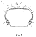
- Figure 1 is a cross sectional view of a tyre according to the present invention;
- Figure 2 is a developed plan view showing the carcass and band thereof;
- Figures 3 and 4 are respectively a side view and a developed partial plan view of another example of the band;
- Figure 5 is a perspective view of a ribbon of rubber used to form the band; and
- Figure 6 is a sectional view of a modification of the band.
- In Figures 1 and 2, a
pneumatic tyre 1 is a passenger car tyre and has atread portion 2, a pair of axially spaced bead portions 4, and a pair ofsidewall portions 3 extending between the tread edges and the bead portions 4. - The
tyre 1 also has a pair ofbead cores 4A disposed one in each of the bead portions 4, atoroidal carcass 5 extending between the bead portions 4 and turned up around thebead cores 4A, andbelt reinforcements - The
carcass 5 comprises at least one ply of cords and forms two turned up portions and one main portion between thebead cores 4A. - The carcass cords are arranged radially at 60 to 90 degrees with respect to the tyre equator C to provide a radial or so-called semiradial ply structure. For the carcass cords, organic fibre cords, e.g. nylon, aromatic polyamide or the like are used.
- The belt reinforcements in this embodiment comprise a
breaker 6 and a band orbandage 7. Thebreaker 6 is disposed radially outside the carcass crown, and comprises radially inner andouter plies inner breaker ply 6A being wider than the radiallyouter breaker ply 6B. The breaker cords in each ply are laid at an angle of 15 to 40 degrees with respect to the tyre equator C and parallel with each other, but crosswise to the cords in the next ply. For the breaker cords, high elastic modulus cords, e.g. steel cords, organic fibre cords such as aromatic polyamide fibre cords or the like are used. - The
band 7 is the radially outermost reinforcing cord layer and is disposed on the radially outer surface of thebreaker 6 and extends axially across the whole width of thebreaker 6 to reach the breaker edges. Thus the edges F1 and F2 of theband 7 in this embodiment are aligned with the breaker edges, but they can project outside the edges to give an edge overlap. Theband 7 is made of parallel cords wound spirally around thebreaker 6 continuously from one edge to the other edge thereof. The number of parallel cords is preferably in the range of 6 to 20. - The band 4 in this embodiment composed as shown in Figure 2, is of two circumferential portions, a parallel cord portion J and an inclined cord portion K.
- The parallel cord portion J is such that the cords of the windings of the band are laid parallel to the tyre equator C.
- The inclined cord portion K is such that the cords in the windings of the band are laid in these portions at a small angle (alpha) of 0.3 to 5 degrees, more preferably 1 to 3 degrees, with respect to the tyre equator C.
- The circumferential length of the inclined cord portion K is 20 to 50% of the whole circumferential length.
- If the circumferential length of the inclined cord portion K is less than 20%, the inclination angle becomes excessively large, and it becomes too difficult to make such a band.
- If more than 50%, the parallel cord portion J becomes too short and uniformity is not be improved.
- Figures 3 to 4 show another example of the band, in which the
band 7 is composed of alternate parallel cord portions and inclined cord portions. In this example, theband 7 is composed of alternate three parallel cord portions J1, J2 and J3 and three inclined cord portions K1, K2 and K3. - The inclined cord portions K1-K3 have substantially the same circumferential lengths, the total of which is not more than 25% of the whole circumferential length of the band.
- Also the parallel cord portions J1-J3 have substantially the same circumferential lengths.
- If the total circumferential length of the inclined cord portions is more than 25%, sufficient uniformity is not be obtained, and durability is impaired.
- The inclined cord portions K1, K2 and K3 (and accordingly the parallel cord portions) are disposed symmetrically around the tyre axis at substantially regular pitch angles (in this example every 120 degrees).
- The windings of the band cords in each inclined cord portion are also laid at a small angle (alpha) of 0.3 to 5 degrees, more preferably 1 to 3 degrees, with respect to the tyre equator C, and those in each parallel cord portion are parallel with the tyre equator C.
- The above-mentioned
bands 7 are formed by winding a ribbon ofrubber 10 shown in Figure 5. Theribbon 10 is such that theband cords 11 are embedded in coatingrubber 12 parallel to each other along the longitudinal direction thereof. The cross sectional shape of theribbon 10 in this example is a flat rectangle. - Preferably organic fibre cords having a heat shrinking nature such as 66-nylon are used. By using such cords, the band cords are shrunk during vulcanisation to increase the hoop force of the band, and the tyre uniformity is improved.
- In the widthwise direction of the
ribbon 10, thecords 11 are laid at substantially regular intervals, and the number of cords is preferably in the range of 6 to 20 as explained above. - When the cord number is less than 6, the width W1 of the
ribbon 10 becomes too small and the winding number or the number of windings of the ribbon is increased, which lowers the productivity and increases the manufacturing cost of the tyre. - When the number is more than 20, the width W1 of the
ribbon 10 becomes too large, and as a result the cord inclination angle in the inclined cord portion is increased and the tyre uniformity is deteriorated. - Starting from the band edge F1, the
ribbon 10 is wound around the radially outside of thebreaker 6 spirally and continuously to the other band edge F2. - As shown in Figures 2 and 4, in the parallel cord portions J, J1-J3 the
ribbon 10 is wound parallel to the tyre equator C, and in the inclined cord portions K, K1-K3 the ribbon is wound at the above mentioned small inclination angle (alpha). - In the above-mentioned examples, the
ribbon 10 is wound closely so that the windings are not overlapped except in the band edge portions. In the edge portion, theribbon 10 is wound along the band edge F1, F2 for at least one turn to make the axially outermost winding, the whole of which is parallel with the tyre equator C, and which is overlapped with the next winding, so that the ends of theribbon 10 are prevented from loosening, and to provide a further reinforcement at the breaker edges to prevent breaker edge separation failure. - Passing through the sole inclined cord portion (Figures 1-2) or all of the inclined cord portions (Figures 3-4), the
ribbon 10 is progressed by one spiral pitch. In other words, in order to progress the ribbon one spiral pitch, the width of the ribbon (or the number of the embedded cords), the overlap width and the like are determined based on the above-mentioned limitations for the inclination angle and the total circumferential length of the inclined cord portion(s). - If the inclination angle (alpha) is more than 5 degrees, which means that the bent angle of the
ribbon 10 at the boundary between the parallel and inclined cord portions is more than 5 degrees, an undesirable stress is caused around the boundary, and further it becomes difficult to make such a band. - The joint of the tread rubber which is wound on to the outside of the band and the circumferential ends or joint of the breaker ply are preferably disposed within the parallel cord portion(s), whereby separation failure during high speed running can be avoided.
- As explained above, in the two examples, the windings of the
ribbon 10 are not overlapped except in the band edge portions. However, it can be overlapped over all the width as shown in Figure 6. The overlap widths L can be constant through all the width, but it is also possible to vary the overlap widths in the axial direction such that the overlap widths increase gradually from the tread centre towards the tread edges, or the overlap widths in the tread shoulder regions are larger than those in the tread crown region. - Further, it is possible to wind the ribbon in an opened state where adjacent turns have their edges spaced apart by a small distance.
- Furthermore, immediately inside the above explained band 7 a similar band can be disposed so as to provide the tyre with a double-layered band structure.
- As described above, in pneumatic tyres according to the present invention, the spiral cord band comprises the major parallel cord portion and the minor inclined cord portion, whereby tyre uniformity and high speed durability are improved.
Claims (8)
- A pneumatic tyre comprising a carcass (5) having at least one ply of cords extending between bead portions (4), and a band (7) disposed radially outside the carcass (5) and inside a tread (2) made of parallel cords wound spirally around a breaker (6), characterised in that the band (7) comprises two circumferential portions (J,K) which are a parallel cord portion (J) in which the windings of the band cords are laid parallel to the tyre equator (C) and an inclined cord portion (K) in which the windings of the band cords are laid at an inclination angle of 0.3 to 5 degrees to the tyre equator (C), the circumferential length of the inclined cord portion (K) being less than 50% of the whole circumferential length of the band (7).
- A pneumatic tyre according to claim 1 characterised in that the circumferential length of the inclined cord portion (K) being more than 20% of the whole circumferential length of the band (7).
- A pneumatic tyre according to claim 1 or 2 characterised in that the band (7) comprises a plurality of circumferential portions including at least two parallel cord portions (J1,J2,J3) in which the windings of the band cords are laid parallel to the tyre equator (C) and at least two inclined cord portions (K1,K2,K3) in which the windings of the band cords are laid at an inclination angle of 0.3 to 5 degrees of the tyre equator, said at least two inclined cord portions (K1,K2,K3) being disposed substantially symmetrically around the tyre axis, and the total circumferential length of said at least two inclined cord portions (K1,K2,K3) are not more than 25% of the whole circumferential length of the band (7).
- A tyre according to claim 3, characterised in that the inclined cord portions (K1,K2,K3) have substantially the same circumferential length the total of which is not more than 25% of the whole circumferential length of the band (7).
- A tyre according to claim 3 or 4, characterised in that the parallel cord portions (J1,J2,J3) have substantially the same circumferential length.
- A tyre according to claim 3, 4 or 5, characterised in that the inclined cord portions (K1,K2,K3) are disposed symmetrically around the tyre axis in substantially regular pitched angles.
- A tyre according to any one of claims 1 to 6, characterised in that the inclination angles is in the range of 0.3 to 5 degrees.
- A tyre according to any one of claims 1 to 7, characterised in that the inclination angle is in the range of 1 to 3 degrees.
Applications Claiming Priority (4)
| Application Number | Priority Date | Filing Date | Title |
|---|---|---|---|
| JP287932/90 | 1990-10-24 | ||
| JP2287932A JPH085283B2 (en) | 1990-10-24 | 1990-10-24 | Pneumatic tire |
| JP2298386A JP2895952B2 (en) | 1990-11-02 | 1990-11-02 | Pneumatic tire |
| JP298386/90 | 1990-11-02 |
Publications (2)
| Publication Number | Publication Date |
|---|---|
| EP0482898A1 true EP0482898A1 (en) | 1992-04-29 |
| EP0482898B1 EP0482898B1 (en) | 1994-12-21 |
Family
ID=26556945
Family Applications (1)
| Application Number | Title | Priority Date | Filing Date |
|---|---|---|---|
| EP91309771A Expired - Lifetime EP0482898B1 (en) | 1990-10-24 | 1991-10-22 | Pneumatic tyre |
Country Status (4)
| Country | Link |
|---|---|
| US (1) | US5178703A (en) |
| EP (1) | EP0482898B1 (en) |
| CA (1) | CA2053336C (en) |
| DE (1) | DE69106104T2 (en) |
Cited By (2)
| Publication number | Priority date | Publication date | Assignee | Title |
|---|---|---|---|---|
| FR2696980A1 (en) * | 1992-10-20 | 1994-04-22 | Michelin & Cie | Tyre with tread reinforcement formed from a continuously wound band - of rubber coated textile plies laid in zig-zag form with straight sections both parallel to, and inclined to, the tyre circumference and included at angle theta to it, improving resistance to shock damage partic. for military vehicles |
| EP3539797A1 (en) * | 2018-03-12 | 2019-09-18 | Sumitomo Rubber Industries Ltd. | Tire |
Families Citing this family (11)
| Publication number | Priority date | Publication date | Assignee | Title |
|---|---|---|---|---|
| US6412533B1 (en) | 1997-12-29 | 2002-07-02 | Pirelli Pneumatici S.P.A. | High transverse-curvature tire for two-wheeled vehicles including specified belt structure |
| US6397911B1 (en) | 1997-12-29 | 2002-06-04 | Pirelli Pneumatici S.P.A. | High transverse-curvature motor-bike tire |
| JP2006069130A (en) * | 2004-09-03 | 2006-03-16 | Toyo Tire & Rubber Co Ltd | Tire and tire molding method |
| WO2006075455A1 (en) * | 2005-01-13 | 2006-07-20 | Bridgestone Corporation | Pneumatic tire |
| JP5174338B2 (en) * | 2006-09-29 | 2013-04-03 | 株式会社ブリヂストン | Radial tire for aircraft and method for manufacturing the same |
| JP5735810B2 (en) * | 2011-01-14 | 2015-06-17 | 株式会社ブリヂストン | Pneumatic tire and method for forming circumferential belt layer in pneumatic tire |
| JP2013043298A (en) * | 2011-08-22 | 2013-03-04 | Sumitomo Rubber Ind Ltd | Method for manufacturing tire |
| JP6092783B2 (en) * | 2011-11-02 | 2017-03-08 | 株式会社ブリヂストン | Pneumatic radial tire for passenger cars |
| JP5957430B2 (en) * | 2013-10-24 | 2016-07-27 | 住友ゴム工業株式会社 | Pneumatic tire and manufacturing method thereof |
| JP6572105B2 (en) * | 2015-11-16 | 2019-09-04 | Toyo Tire株式会社 | tire |
| JP7381869B2 (en) * | 2019-12-18 | 2023-11-16 | 横浜ゴム株式会社 | Pneumatic tires and pneumatic tire manufacturing methods |
Citations (3)
| Publication number | Priority date | Publication date | Assignee | Title |
|---|---|---|---|---|
| GB815055A (en) * | 1955-03-16 | 1959-06-17 | Pirelli | Improvements relating to pneumatic vehicle wheel tyres |
| EP0258822A2 (en) * | 1986-09-03 | 1988-03-09 | Continental Aktiengesellschaft | Vehicle tyre |
| DE3911031A1 (en) * | 1988-04-05 | 1989-10-26 | Toyo Tire & Rubber Co | Radial tyre for passenger cars |
Family Cites Families (6)
| Publication number | Priority date | Publication date | Assignee | Title |
|---|---|---|---|---|
| US3991803A (en) * | 1974-11-11 | 1976-11-16 | The B. F. Goodrich Company | Pneumatic tire with reinforced tread |
| JPH0741768B2 (en) * | 1984-04-05 | 1995-05-10 | 住友ゴム工業株式会社 | Pneumatic tire |
| JPS6115604A (en) * | 1984-06-29 | 1986-01-23 | 井関農機株式会社 | Rolling control apparatus |
| JPH01132404A (en) * | 1987-11-16 | 1989-05-24 | Bridgestone Corp | Pneumatic tyre |
| US4869307A (en) * | 1988-03-17 | 1989-09-26 | The Goodyear Tire & Rubber Company | Pneumatic tire and method for making same |
| US4989658A (en) * | 1989-06-09 | 1991-02-05 | The Goodyear Tire & Rubber Company | Belt overlay structure for pneumatic tires comprising a single ribbon wrapped about the belt structure |
-
1991
- 1991-10-09 US US07/773,263 patent/US5178703A/en not_active Expired - Lifetime
- 1991-10-11 CA CA002053336A patent/CA2053336C/en not_active Expired - Lifetime
- 1991-10-22 EP EP91309771A patent/EP0482898B1/en not_active Expired - Lifetime
- 1991-10-22 DE DE69106104T patent/DE69106104T2/en not_active Expired - Lifetime
Patent Citations (3)
| Publication number | Priority date | Publication date | Assignee | Title |
|---|---|---|---|---|
| GB815055A (en) * | 1955-03-16 | 1959-06-17 | Pirelli | Improvements relating to pneumatic vehicle wheel tyres |
| EP0258822A2 (en) * | 1986-09-03 | 1988-03-09 | Continental Aktiengesellschaft | Vehicle tyre |
| DE3911031A1 (en) * | 1988-04-05 | 1989-10-26 | Toyo Tire & Rubber Co | Radial tyre for passenger cars |
Non-Patent Citations (1)
| Title |
|---|
| PATENT ABSTRACTS OF JAPAN vol. 10, no. 70 (M-462)(2127) 19 June 1986 & JP-A-60 213 505 ( SUMITOMO GOMU KOGYO K.K. ) 25 October 1985 * |
Cited By (2)
| Publication number | Priority date | Publication date | Assignee | Title |
|---|---|---|---|---|
| FR2696980A1 (en) * | 1992-10-20 | 1994-04-22 | Michelin & Cie | Tyre with tread reinforcement formed from a continuously wound band - of rubber coated textile plies laid in zig-zag form with straight sections both parallel to, and inclined to, the tyre circumference and included at angle theta to it, improving resistance to shock damage partic. for military vehicles |
| EP3539797A1 (en) * | 2018-03-12 | 2019-09-18 | Sumitomo Rubber Industries Ltd. | Tire |
Also Published As
| Publication number | Publication date |
|---|---|
| CA2053336A1 (en) | 1992-04-25 |
| CA2053336C (en) | 2002-12-10 |
| DE69106104D1 (en) | 1995-02-02 |
| EP0482898B1 (en) | 1994-12-21 |
| DE69106104T2 (en) | 1995-05-11 |
| US5178703A (en) | 1993-01-12 |
Similar Documents
| Publication | Publication Date | Title |
|---|---|---|
| US7360571B2 (en) | Pneumatic tire with composite belt structure | |
| CA1295537C (en) | Pneumatic tire | |
| EP1449680B1 (en) | A tire having a composite belt structure | |
| US5441093A (en) | Motorcycle radial tire with folded breaker ply and spirally wound band ply | |
| EP0482898B1 (en) | Pneumatic tyre | |
| EP4234272B1 (en) | Pneumatic tire | |
| EP0542567B1 (en) | Pneumatic tyre | |
| EP2199106B1 (en) | Pneumatic tire | |
| JPH10236109A (en) | Pneumatic tire having reinforcement belt type assembly | |
| EP3895910B1 (en) | Tire with cut protector belt structure | |
| JPH0446802A (en) | Pneumatic radial tire suitable for high speed drive | |
| EP0425318A2 (en) | Pneumatic radial tires | |
| US6966351B2 (en) | Tire bead configuration | |
| EP2199107B1 (en) | Pneumatic tire | |
| US4733706A (en) | Pneumatic tire | |
| EP0053997A1 (en) | A pneumatic tire and method for making same | |
| US5386866A (en) | Radial tire with band formed from plural ribbons | |
| EP0401444A2 (en) | Pneumatic radial tire | |
| ZA200909066B (en) | Pneumatic tire | |
| EP4015243B1 (en) | Tire with protective belt structure | |
| US20070144649A1 (en) | Overlay configuration for a tire | |
| EP3838622B1 (en) | Pneumatic tire | |
| EP1226041A1 (en) | Motorcycle radial tyre | |
| JP2895952B2 (en) | Pneumatic tire | |
| JPH04163213A (en) | Pneumatic tire |
Legal Events
| Date | Code | Title | Description |
|---|---|---|---|
| PUAI | Public reference made under article 153(3) epc to a published international application that has entered the european phase |
Free format text: ORIGINAL CODE: 0009012 |
|
| AK | Designated contracting states |
Kind code of ref document: A1 Designated state(s): DE FR GB |
|
| 17P | Request for examination filed |
Effective date: 19920625 |
|
| RIN1 | Information on inventor provided before grant (corrected) |
Inventor name: YAMAMORI, SYUICHI Inventor name: ONODA, MAKOTO Inventor name: SAKUNO, HIROAKI, 1-44 AZA-MIYAKOBASHIYAMA Inventor name: HIROSAWA, YOUICHIRO |
|
| 17Q | First examination report despatched |
Effective date: 19931119 |
|
| GRAA | (expected) grant |
Free format text: ORIGINAL CODE: 0009210 |
|
| AK | Designated contracting states |
Kind code of ref document: B1 Designated state(s): DE FR GB |
|
| REF | Corresponds to: |
Ref document number: 69106104 Country of ref document: DE Date of ref document: 19950202 |
|
| ET | Fr: translation filed | ||
| PLBE | No opposition filed within time limit |
Free format text: ORIGINAL CODE: 0009261 |
|
| STAA | Information on the status of an ep patent application or granted ep patent |
Free format text: STATUS: NO OPPOSITION FILED WITHIN TIME LIMIT |
|
| 26N | No opposition filed | ||
| REG | Reference to a national code |
Ref country code: GB Ref legal event code: IF02 |
|
| PGFP | Annual fee paid to national office [announced via postgrant information from national office to epo] |
Ref country code: DE Payment date: 20091015 Year of fee payment: 19 |
|
| PGFP | Annual fee paid to national office [announced via postgrant information from national office to epo] |
Ref country code: FR Payment date: 20091029 Year of fee payment: 19 Ref country code: GB Payment date: 20091021 Year of fee payment: 19 |
|
| GBPC | Gb: european patent ceased through non-payment of renewal fee |
Effective date: 20101022 |
|
| PG25 | Lapsed in a contracting state [announced via postgrant information from national office to epo] |
Ref country code: FR Free format text: LAPSE BECAUSE OF NON-PAYMENT OF DUE FEES Effective date: 20101102 |
|
| REG | Reference to a national code |
Ref country code: FR Ref legal event code: ST Effective date: 20110630 |
|
| REG | Reference to a national code |
Ref country code: DE Ref legal event code: R119 Ref document number: 69106104 Country of ref document: DE Effective date: 20110502 |
|
| PG25 | Lapsed in a contracting state [announced via postgrant information from national office to epo] |
Ref country code: GB Free format text: LAPSE BECAUSE OF NON-PAYMENT OF DUE FEES Effective date: 20101022 |
|
| PG25 | Lapsed in a contracting state [announced via postgrant information from national office to epo] |
Ref country code: DE Free format text: LAPSE BECAUSE OF NON-PAYMENT OF DUE FEES Effective date: 20110502 |