EP0482856A1 - Brenner mit einem intermittierend funktionierenden Zündbrenner und einer Vor-Zündungsprüfung - Google Patents
Brenner mit einem intermittierend funktionierenden Zündbrenner und einer Vor-Zündungsprüfung Download PDFInfo
- Publication number
- EP0482856A1 EP0482856A1 EP91309690A EP91309690A EP0482856A1 EP 0482856 A1 EP0482856 A1 EP 0482856A1 EP 91309690 A EP91309690 A EP 91309690A EP 91309690 A EP91309690 A EP 91309690A EP 0482856 A1 EP0482856 A1 EP 0482856A1
- Authority
- EP
- European Patent Office
- Prior art keywords
- igniter
- pilot
- burner
- signal
- responsive
- Prior art date
- Legal status (The legal status is an assumption and is not a legal conclusion. Google has not performed a legal analysis and makes no representation as to the accuracy of the status listed.)
- Withdrawn
Links
Images
Classifications
-
- F—MECHANICAL ENGINEERING; LIGHTING; HEATING; WEAPONS; BLASTING
- F23—COMBUSTION APPARATUS; COMBUSTION PROCESSES
- F23Q—IGNITION; EXTINGUISHING-DEVICES
- F23Q23/00—Testing of ignition installations
-
- F—MECHANICAL ENGINEERING; LIGHTING; HEATING; WEAPONS; BLASTING
- F23—COMBUSTION APPARATUS; COMBUSTION PROCESSES
- F23N—REGULATING OR CONTROLLING COMBUSTION
- F23N5/00—Systems for controlling combustion
- F23N5/20—Systems for controlling combustion with a time programme acting through electrical means, e.g. using time-delay relays
- F23N5/203—Systems for controlling combustion with a time programme acting through electrical means, e.g. using time-delay relays using electronic means
-
- F—MECHANICAL ENGINEERING; LIGHTING; HEATING; WEAPONS; BLASTING
- F23—COMBUSTION APPARATUS; COMBUSTION PROCESSES
- F23Q—IGNITION; EXTINGUISHING-DEVICES
- F23Q9/00—Pilot flame igniters
-
- F—MECHANICAL ENGINEERING; LIGHTING; HEATING; WEAPONS; BLASTING
- F23—COMBUSTION APPARATUS; COMBUSTION PROCESSES
- F23N—REGULATING OR CONTROLLING COMBUSTION
- F23N2223/00—Signal processing; Details thereof
- F23N2223/22—Timing network
-
- F—MECHANICAL ENGINEERING; LIGHTING; HEATING; WEAPONS; BLASTING
- F23—COMBUSTION APPARATUS; COMBUSTION PROCESSES
- F23N—REGULATING OR CONTROLLING COMBUSTION
- F23N2227/00—Ignition or checking
- F23N2227/22—Pilot burners
-
- F—MECHANICAL ENGINEERING; LIGHTING; HEATING; WEAPONS; BLASTING
- F23—COMBUSTION APPARATUS; COMBUSTION PROCESSES
- F23N—REGULATING OR CONTROLLING COMBUSTION
- F23N2227/00—Ignition or checking
- F23N2227/38—Electrical resistance ignition
-
- F—MECHANICAL ENGINEERING; LIGHTING; HEATING; WEAPONS; BLASTING
- F23—COMBUSTION APPARATUS; COMBUSTION PROCESSES
- F23N—REGULATING OR CONTROLLING COMBUSTION
- F23N2231/00—Fail safe
- F23N2231/12—Fail safe for ignition failures
-
- F—MECHANICAL ENGINEERING; LIGHTING; HEATING; WEAPONS; BLASTING
- F23—COMBUSTION APPARATUS; COMBUSTION PROCESSES
- F23N—REGULATING OR CONTROLLING COMBUSTION
- F23N2235/00—Valves, nozzles or pumps
- F23N2235/12—Fuel valves
- F23N2235/14—Fuel valves electromagnetically operated
-
- F—MECHANICAL ENGINEERING; LIGHTING; HEATING; WEAPONS; BLASTING
- F23—COMBUSTION APPARATUS; COMBUSTION PROCESSES
- F23N—REGULATING OR CONTROLLING COMBUSTION
- F23N5/00—Systems for controlling combustion
- F23N5/02—Systems for controlling combustion using devices responsive to thermal changes or to thermal expansion of a medium
- F23N5/12—Systems for controlling combustion using devices responsive to thermal changes or to thermal expansion of a medium using ionisation-sensitive elements, i.e. flame rods
-
- F—MECHANICAL ENGINEERING; LIGHTING; HEATING; WEAPONS; BLASTING
- F23—COMBUSTION APPARATUS; COMBUSTION PROCESSES
- F23N—REGULATING OR CONTROLLING COMBUSTION
- F23N5/00—Systems for controlling combustion
- F23N5/24—Preventing development of abnormal or undesired conditions, i.e. safety arrangements
Definitions
- Such an igniter typically comprises a short piece of conductive silicon carbide or other conductive refractory material placed in proximity to the fuel jets and through which is passed a current of sufficient magnitude to cause it to be heated to a temperature of at least 1000 °C.
- the control system for the fuel burner includes an igniter sensing means in sensing relation to the igniter for providing an igniter signal responsive to operation of the igniter.
- a pilot valve control means receives the igniter signal and provides the pilot valve control signal which controls the pilot burner valve responsive to the igniter signal. If the igniter is a hot surface igniter, the igniter signal is conditioned on either or both of the voltage across the igniter element being within a predetermined voltage range or on current flow through the igniter being within a predetermined current range.
- one purpose of this invention is to prevent the pilot valve from being turned on until the igniter has been checked for proper operation.
- Another purpose of this invention is to avoid nuisance lockouts arising from timing out during pilot light ignition.
- Yet another purpose is to avoid the need for an ignition timer, thereby simplifying the burner control system.
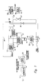
- Fig. 1 is a simplified control circuit implementing the invention.
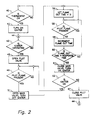
- Fig. 2 is a flow diagram showing the sequence of operations of the invention, and on which may be based the part of a program for a microprocessor which implements the invention.
- Fig. 1 There are two different aspects of this invention.
- One comprises actual hardware and is shown in Fig. 1. It is also possible to accomplish the same control functions by use of a microprocessor which is programmed to direct execution of these functions, and Fig. 2 depicts a flow diagram or chart which can form the logical structure for suitable instructions implementing the invention.
- Fig. 2 depicts a flow diagram or chart which can form the logical structure for suitable instructions implementing the invention.
- the two types of embodiments are understood to be completely equivalent, although there are features shown in Fig. 2 which are not provided by the simplified hardware implementation of Fig. 1.
- Fig. 1 the hardware implementation shown therein has a conventional thermostat 12 which switches a control voltage V0 (24 VAC is standard) to provide when closed a demand signal on path 14.
- the control voltage V0 also typically serves to supply the power for operating the control system of which the elements of this invention form a part.
- the electro-mechanical and other non-logic components typically use the control voltage V0 on path 14 directly as is symbolized in Fig. 1, with path 14 shown as connected to various of these components such as igniter power supply 14 and valve drivers 22 and 28.
- a power supply 11 receives the demand signal/control voltage and supplies DC voltage on a power bus 30 for powering the logic and other electronic components.
- the igniter power supply 13 provides power directly to an igniter 15 whenever enabled by a flame signal supplied by a flame response timer 29.
- a logical 0 value for the flame signal on path 26 is implying absence of a flame
- a logical 1 value is implying presence of a flame.
- power supply 11 provides power to igniter 15 when a logical 0, implying no flame, is encoded in the flame signal.
- the igniter 15 is placed adjacent to a pilot burner 23 so that when fuel is supplied to the burner 23 and the igniter 15 is receiving the proper power from supply 13, the pilot flame will be lit.
- a voltage sensor 19 and a current sensor 18 Operation of the igniter 15 is monitored by a voltage sensor 19 and a current sensor 18. Voltage across the igniter 15 and the igniter power supply 13 is monitored by a voltage sensor 18. Both voltage sensor 19 and current sensor 18 are of the type which provide a logic level signal on path 17 or 21 respectively. Each of these sensor output signals is suitable to function as a logical or Boolean input to an AND gate 16. When voltage across or current flow from power supply 13 is within a predetermined voltage or current range it can be inferred that igniter 15 and its power supply 13 are both operating properly. To indicate this, the output from the sensor involved is a logical 1. If no or too low a voltage is present at the output of power supply 13, then it is likely that the power supply is not operating properly.
- the AND gate 16 is one of the electronic components receiving its power from power supply 11. If both sensor signals are logical 1 then AND gate 16 provides an igniter signal comprising a logical 1 on path 32. Presence of the igniter signal virtually guarantees that igniter 15 is operating and therefore capable of lighting any combustible fuel mixture surrounding it.
- valve driver 22 causes pilot burner valve 21 to open allowing fuel to flow to both flow restricter 25 and main burner valve 27. Fuel flows through restricter 25 to pilot burner 23 where it mixes with air and is ignited by igniter 15 to form a pilot flame.
- the control voltage on path 14 directly powers both valve 31 as well as main burner valve 27 as shown.
- a pilot flame sensor 20 within sensing distance of the pilot burner 23 responds by providing a flame present signal to a flame response timer 29.
- Timer 29 in cooperation with sensor 20 then provides a Boolean 1 flame signal output when flame is present.
- the flame signal on path 26 thus no longer enables igniter power supply 13 so the power output from supply 13 to igniter 15 ceases.
- timer 29 maintains the logical 1 output for a short period of time, perhaps a second or so, even if not sensing presence of a pilot flame, so as to accommodate temporary instabilities in the pilot flame without immediately changing the flame signal.
- timer 29 changes its output to a logical 0, reenabling the igniter power supply 13.
- the flame signal on path 26 is also supplied to a valve driver 28 which in turn responds to a logical 1 value of it by causing main burner valve 27 to open. Since valve 31 is open as well, fuel therefore flows to main burner 24. The fuel mixes with air and the pilot flame ignites the main burner 24, thereby completing the ignition sequence.
- the logical 0 value for the flame signal causes the main valve to close because driver 28 is no longer enabled. If the igniter 15 is operating properly in response to the logical 0 flame signal value, the pilot valve 11 will remain open, and restarting the pilot and main burners will occur.
- igniter 15 be a hot surface igniter.
- Such an igniter is made from a refractory conductor such as silicon carbide, which has intrinsic resistance allowing it to be electrically heated to perhaps 1000 °C which is sufficient to ignite a suitable fuel mixture.
- a hot surface type of igniter 15 has sufficiently low resistance to cause a measurable drop in power supply 13 voltage from the open circuit value.
- Voltage sensor 19 preferably provides its Boolean 1 sensor signal when the igniter 15 voltage magnitude reflects ability of the igniter to ignite the pilot burner fuel, and provides a Boolean 0 signal when the igniter is unable to light the pilot.
- current sensor 21 provides a Boolean 1 output when current flow to igniter 15 indicates the present ability of igniter 15 to ignite fuel flowing from pilot burner 23.
- spark igniter 15 it is also possible, though not currently preferred, to use a spark igniter as igniter 15. Since the voltage and current required by a spark igniter is completely different from that of a hot surface igniter, it is likely that completely different types of sensors will be required, although a similar arrangement to sense operation of a spark igniter is possible.
- the flow diagram of Fig. 2 shows the sequence of operation for the hardware implementation shown in Fig. 1. It is also possible to incorporate these activities in object code based on this flow diagram which can be used with a microprocessor which receives the sensor or condition signals of the thermostat 12, igniter sensor 18 and flame sensor 20 shown in Fig. 1. The microprocessor also supplies control signals for the operation of valves 21 and 27 and the igniter power supply 13 in Fig. 1. At the present time it is preferred to implement the invention in hardware, but this may well become untrue in the future.
- the diamond-shaped decision elements represent decision-making microprocessor instruction sequences based on a thermostat or sensor signal.
- the rectangular boxes are either control elements representing instructions which set the open or closed condition of a valve or turn the igniter power supply 18 on or off or activity elements which change an internal condition of the microprocessor.
- an ignition sequence starts with the instructions comprising the decision element 40 which senses whether the thermostat 12 is off or on, and if on, processing passes to the instructions comprising the control element 42.
- the instructions comprising element 42 cause the microprocessor to issue a signal to the igniter power supply 13 to supply power to the igniter 15.
- the instructions of element 43 test the igniter signal output of the voltage sensor 18 and if the voltage across power supply 13 indicates the igniter 15 is operating, then operation passes to the instructions of element 45. If the sensor 18 output indicates that igniter 15 is not operating properly, then instruction execution returns to the instructions of element 42.
- control element 45 executes the control element 45 instructions, resulting in the issuing of a pilot valve control signal causing the pilot valve 21 to open.
- the instructions of decision element 49 are executed, which sense the pilot signal output of flame sensor 20 and transfer instruction execution to control element 51 if the pilot signal is present. If the pilot signal is not present, then the instructions of element are continuously executed until the pilot flame is sensed.
- control element 51 Execution of the instructions forming control element 51 cause the microprocessor to issue a control signal to main valve 27 which causes main valve 27 to open. Fuel then flows to the main burner 24 and shortly thereafter, normal operation results in ignition of the main burner flame by the pilot burner flame. The instructions of element 51 also turn the igniter 15 off.
- the pilot flame will be extinguished even while the main valve 27 is open. For example, there may be an interruption in the supply of fuel or the pilot flame may be blown out by the rush of main burner fuel without the main burner 24 igniting. If such a condition arises, the pilot signal will vanish. This is potentially a very dangerous situation, with the main and pilot valves open and no flame burning the flowing fuel.
- This condition is detected by the instructions of elements 54, 55, and 56. After the main valve has been opened by the execution of the instructions of element 51, the function of activity element 54 is performed. These instructions clear an internal memory cell which stores a flame out time value.
- the instructions of element 55 test the pilot signal to determine whether the pilot flame is present.
- operation is transferred to the instructions of activity element 56, which increments the time which the pilot flame is sensed not present. After each instance of this incrementation, the new time value is tested by the instructions of decision element 60 to exceed a pilot sensor response time, and if the flame out time is greater than this response time then execution passes to the instructions of control element 61. If the flame out time is not greater than the response time, then operation transfers back to the element 55 instructions to again test the pilot signal and increment the time if there is no pilot flame.
- Control element 61 comprises instructions which cause the microprocessor to issue signals causing the main fuel valve 27 to close and the igniter power source 13 to turn on again.
- the instructions of element 62 test whether the igniter 15 is receiving power, and if so, passes control to the decision element 49 instructions which, as explained above, test for presence of the pilot flame. If the igniter 15 is sensed to be inoperable, then the microprocessor transfers execution of instructions to those of control element 67 which cause the pilot valve to close. Instruction execution then continues withe the instructions of element 43, as symbolized by the connector element A 44, in essence restarting the ignition sequence.
- microprocessor software which deal with ignition and flame safety within the burner of which the elements of Figs. 1 and 2 form a part.
- the microprocessor may have many other safety and operating functions for the furnace as well as these just described.
Landscapes
- Engineering & Computer Science (AREA)
- Chemical & Material Sciences (AREA)
- Combustion & Propulsion (AREA)
- Mechanical Engineering (AREA)
- General Engineering & Computer Science (AREA)
- Control Of Combustion (AREA)
Applications Claiming Priority (2)
| Application Number | Priority Date | Filing Date | Title |
|---|---|---|---|
| US07/600,801 US5035607A (en) | 1990-10-22 | 1990-10-22 | Fuel burner having an intermittent pilot with pre-ignition testing |
| US600801 | 1990-10-22 |
Publications (1)
| Publication Number | Publication Date |
|---|---|
| EP0482856A1 true EP0482856A1 (de) | 1992-04-29 |
Family
ID=24405108
Family Applications (1)
| Application Number | Title | Priority Date | Filing Date |
|---|---|---|---|
| EP91309690A Withdrawn EP0482856A1 (de) | 1990-10-22 | 1991-10-21 | Brenner mit einem intermittierend funktionierenden Zündbrenner und einer Vor-Zündungsprüfung |
Country Status (2)
| Country | Link |
|---|---|
| US (1) | US5035607A (de) |
| EP (1) | EP0482856A1 (de) |
Cited By (2)
| Publication number | Priority date | Publication date | Assignee | Title |
|---|---|---|---|---|
| US5416300A (en) * | 1993-03-05 | 1995-05-16 | Landis & Gyr Business Support Ag | Electric igniter actuator with network voltage clocking to pass only a portion of the wave trains to the igniter |
| EP0931990A3 (de) * | 1998-01-23 | 2001-12-12 | Tridelta Industries, Inc. | Gerätsteuerung |
Families Citing this family (22)
| Publication number | Priority date | Publication date | Assignee | Title |
|---|---|---|---|---|
| US5201010A (en) * | 1989-05-01 | 1993-04-06 | Credit Verification Corporation | Method and system for building a database and performing marketing based upon prior shopping history |
| US5435717A (en) * | 1993-04-30 | 1995-07-25 | Honeywell Inc. | Burner control system with continuous check of hot surface ignitor during run cycle |
| US5528226A (en) * | 1994-06-24 | 1996-06-18 | Advanced Micro Devices Inc. | Apparatus and method for controlling the burn-off operation of a gas in a semiconductor wafer fabrication furnace |
| US5538416A (en) * | 1995-02-27 | 1996-07-23 | Honeywell Inc. | Gas burner controller with main valve delay after pilot flame lightoff |
| US5951276A (en) * | 1997-05-30 | 1999-09-14 | Jaeschke; James R. | Electrically enhanced hot surface igniter |
| US7372005B2 (en) * | 2004-09-27 | 2008-05-13 | Aos Holding Company | Water storage device having a powered anode |
| CA2638182A1 (en) * | 2007-08-02 | 2009-02-02 | Owens Corning Intellectual Capital, Llc | Gas supply assembly for mineral fiber apparatus |
| WO2009029287A1 (en) * | 2007-08-28 | 2009-03-05 | Aos Holding Company | Storage-type water heater having tank condition monitoring features |
| WO2009136714A2 (ko) * | 2008-05-06 | 2009-11-12 | 주식회사 대우일렉트로닉스 | 가스식 의류건조기의 제어방법 |
| EP2246626A1 (de) * | 2009-04-30 | 2010-11-03 | Guard Sound Industry Co., Ltd. | Steuerungsschaltung für Magnetventil und Steuerungsverfahren dafür |
| US20110250547A1 (en) * | 2010-04-12 | 2011-10-13 | Ford Global Technologies, Llc | Burner system and a method of control |
| US9494320B2 (en) | 2013-01-11 | 2016-11-15 | Honeywell International Inc. | Method and system for starting an intermittent flame-powered pilot combustion system |
| US10208954B2 (en) | 2013-01-11 | 2019-02-19 | Ademco Inc. | Method and system for controlling an ignition sequence for an intermittent flame-powered pilot combustion system |
| US9386665B2 (en) | 2013-03-14 | 2016-07-05 | Honeywell International Inc. | System for integrated lighting control, configuration, and metric tracking from multiple locations |
| GB201313877D0 (en) * | 2013-08-02 | 2013-09-18 | Dpir Middle East Ltd | Apparatus, method and system for a pilot ignition system |
| US9671113B2 (en) * | 2014-03-28 | 2017-06-06 | Tom Hiroshi Hasegawa | Gas range |
| US11274827B2 (en) * | 2018-01-20 | 2022-03-15 | Surefire Pilotless Burner Systems Llc | Pilot assemblies and methods for elevated flare stacks |
| US11125439B2 (en) | 2018-03-27 | 2021-09-21 | Scp Holdings, An Assumed Business Name Of Nitride Igniters, Llc | Hot surface igniters for cooktops |
| US11236930B2 (en) | 2018-05-01 | 2022-02-01 | Ademco Inc. | Method and system for controlling an intermittent pilot water heater system |
| US11739982B2 (en) | 2019-08-14 | 2023-08-29 | Ademco Inc. | Control system for an intermittent pilot water heater |
| US11656000B2 (en) | 2019-08-14 | 2023-05-23 | Ademco Inc. | Burner control system |
| GB2598970A (en) * | 2020-09-22 | 2022-03-23 | Bosch Thermotechnology Ltd Uk | An air-gas mixture burning appliance with a variable equivalence ratio ignition sequence |
Citations (4)
| Publication number | Priority date | Publication date | Assignee | Title |
|---|---|---|---|---|
| US2395666A (en) * | 1943-06-03 | 1946-02-26 | Raymond M Kaufmann | Electric ignition control |
| US3447880A (en) * | 1966-09-29 | 1969-06-03 | Liberty Combustion Corp | Control system for fluid fuel burners |
| DE2012998A1 (de) * | 1969-03-20 | 1970-10-08 | Robertshaw Controls Company, Richmond, Va. (V.St.A,) | Elektrisches Zündsystem für Brenner |
| DE2044712A1 (de) * | 1969-09-10 | 1971-03-11 | Robertshaw Controls Co | Zündeinrichtung fur Brennstoff brenner |
Family Cites Families (9)
| Publication number | Priority date | Publication date | Assignee | Title |
|---|---|---|---|---|
| US3282324A (en) * | 1965-10-11 | 1966-11-01 | Ram Domestic Products Company | Automatic fuel ignition and heat detection system |
| US3676042A (en) * | 1970-06-25 | 1972-07-11 | Southern California Gas Co | Heater ignition system |
| US4078879A (en) * | 1976-06-04 | 1978-03-14 | Johnson Controls, Inc. | Fuel ignition system control arrangement providing total fuel shutoff and contact protection |
| US4190414A (en) * | 1978-04-17 | 1980-02-26 | W. M. Cissell Manufacturing Company | Fail-safe gas feed and ignition sequence control apparatus and method for a gas-fired appliance |
| US4298335A (en) * | 1979-08-27 | 1981-11-03 | Walter Kidde And Company, Inc. | Fuel burner control apparatus |
| US4323342A (en) * | 1980-01-09 | 1982-04-06 | General Electric Company | Burner ignition and control system |
| US4360338A (en) * | 1980-05-19 | 1982-11-23 | Robertshaw Controls Company | Control system for dual coil pilot valve burner system |
| US4560343A (en) * | 1984-06-11 | 1985-12-24 | Honeywell Inc. | Functional check for a hot surface ignitor element |
| US4746284A (en) * | 1984-06-25 | 1988-05-24 | Robertshaw Controls Company | Hot surface direct ignition system for gas furnaces |
-
1990
- 1990-10-22 US US07/600,801 patent/US5035607A/en not_active Expired - Lifetime
-
1991
- 1991-10-21 EP EP91309690A patent/EP0482856A1/de not_active Withdrawn
Patent Citations (4)
| Publication number | Priority date | Publication date | Assignee | Title |
|---|---|---|---|---|
| US2395666A (en) * | 1943-06-03 | 1946-02-26 | Raymond M Kaufmann | Electric ignition control |
| US3447880A (en) * | 1966-09-29 | 1969-06-03 | Liberty Combustion Corp | Control system for fluid fuel burners |
| DE2012998A1 (de) * | 1969-03-20 | 1970-10-08 | Robertshaw Controls Company, Richmond, Va. (V.St.A,) | Elektrisches Zündsystem für Brenner |
| DE2044712A1 (de) * | 1969-09-10 | 1971-03-11 | Robertshaw Controls Co | Zündeinrichtung fur Brennstoff brenner |
Cited By (2)
| Publication number | Priority date | Publication date | Assignee | Title |
|---|---|---|---|---|
| US5416300A (en) * | 1993-03-05 | 1995-05-16 | Landis & Gyr Business Support Ag | Electric igniter actuator with network voltage clocking to pass only a portion of the wave trains to the igniter |
| EP0931990A3 (de) * | 1998-01-23 | 2001-12-12 | Tridelta Industries, Inc. | Gerätsteuerung |
Also Published As
| Publication number | Publication date |
|---|---|
| US5035607A (en) | 1991-07-30 |
Similar Documents
| Publication | Publication Date | Title |
|---|---|---|
| US5035607A (en) | Fuel burner having an intermittent pilot with pre-ignition testing | |
| US5347982A (en) | Flame monitor safeguard system | |
| US6322352B1 (en) | Gas burner system | |
| US4457692A (en) | Dual firing rate flame sensing system | |
| CA1185164A (en) | Burner ignition and flame monitoring system | |
| EP0385910A2 (de) | Kontrollverfahren für Kraftstoffbrenner mit heisser Oberflächenzündung | |
| US4615282A (en) | Hot surface ignition system control module with accelerated igniter warm-up test program | |
| US4073611A (en) | Control system for gas burning apparatus | |
| US5538416A (en) | Gas burner controller with main valve delay after pilot flame lightoff | |
| US3318358A (en) | Burner igniter system | |
| US3551083A (en) | Fuel burner ignition | |
| US4325689A (en) | Automatic reset control for direct spark ignition systems | |
| US4581697A (en) | Controller for combustible fuel burner | |
| US4106889A (en) | Burner ignition system | |
| KR100189607B1 (ko) | 연소장치 | |
| US4194875A (en) | Intermittent pilot ignition system | |
| US5133656A (en) | Fuel burner valve operator circuit with intermittent ignition | |
| US3741709A (en) | Solid state safety control for fuel burning apparatus | |
| KR100194965B1 (ko) | 가스연소장치 | |
| CA1123934A (en) | Safe start check circuit | |
| US7568908B2 (en) | Low fire start control | |
| JPS6027898B2 (ja) | 燃焼制御装置 | |
| US5456597A (en) | Intelligen transient eliminator for an ignition system | |
| US3480374A (en) | Spark ignition system | |
| US4087230A (en) | Fuel ignition system providing fuel shutoff under simultaneous failure conditions |
Legal Events
| Date | Code | Title | Description |
|---|---|---|---|
| PUAI | Public reference made under article 153(3) epc to a published international application that has entered the european phase |
Free format text: ORIGINAL CODE: 0009012 |
|
| AK | Designated contracting states |
Kind code of ref document: A1 Designated state(s): DE FR GB NL |
|
| 17P | Request for examination filed |
Effective date: 19920826 |
|
| 17Q | First examination report despatched |
Effective date: 19940714 |
|
| STAA | Information on the status of an ep patent application or granted ep patent |
Free format text: STATUS: THE APPLICATION IS DEEMED TO BE WITHDRAWN |
|
| 18D | Application deemed to be withdrawn |
Effective date: 19950809 |