EP0482843A1 - Verbesserte Flüssigkeitssteuereinheit - Google Patents
Verbesserte Flüssigkeitssteuereinheit Download PDFInfo
- Publication number
- EP0482843A1 EP0482843A1 EP91309662A EP91309662A EP0482843A1 EP 0482843 A1 EP0482843 A1 EP 0482843A1 EP 91309662 A EP91309662 A EP 91309662A EP 91309662 A EP91309662 A EP 91309662A EP 0482843 A1 EP0482843 A1 EP 0482843A1
- Authority
- EP
- European Patent Office
- Prior art keywords
- fluid flow
- outer member
- flow control
- edge portion
- outlet
- Prior art date
- Legal status (The legal status is an assumption and is not a legal conclusion. Google has not performed a legal analysis and makes no representation as to the accuracy of the status listed.)
- Granted
Links
Images
Classifications
-
- A—HUMAN NECESSITIES
- A01—AGRICULTURE; FORESTRY; ANIMAL HUSBANDRY; HUNTING; TRAPPING; FISHING
- A01G—HORTICULTURE; CULTIVATION OF VEGETABLES, FLOWERS, RICE, FRUIT, VINES, HOPS OR SEAWEED; FORESTRY; WATERING
- A01G25/00—Watering gardens, fields, sports grounds or the like
- A01G25/02—Watering arrangements located above the soil which make use of perforated pipe-lines or pipe-lines with dispensing fittings, e.g. for drip irrigation
- A01G25/023—Dispensing fittings for drip irrigation, e.g. drippers
-
- B—PERFORMING OPERATIONS; TRANSPORTING
- B29—WORKING OF PLASTICS; WORKING OF SUBSTANCES IN A PLASTIC STATE IN GENERAL
- B29C—SHAPING OR JOINING OF PLASTICS; SHAPING OF MATERIAL IN A PLASTIC STATE, NOT OTHERWISE PROVIDED FOR; AFTER-TREATMENT OF THE SHAPED PRODUCTS, e.g. REPAIRING
- B29C65/00—Joining or sealing of preformed parts, e.g. welding of plastics materials; Apparatus therefor
- B29C65/02—Joining or sealing of preformed parts, e.g. welding of plastics materials; Apparatus therefor by heating, with or without pressure
- B29C65/08—Joining or sealing of preformed parts, e.g. welding of plastics materials; Apparatus therefor by heating, with or without pressure using ultrasonic vibrations
-
- B—PERFORMING OPERATIONS; TRANSPORTING
- B29—WORKING OF PLASTICS; WORKING OF SUBSTANCES IN A PLASTIC STATE IN GENERAL
- B29C—SHAPING OR JOINING OF PLASTICS; SHAPING OF MATERIAL IN A PLASTIC STATE, NOT OTHERWISE PROVIDED FOR; AFTER-TREATMENT OF THE SHAPED PRODUCTS, e.g. REPAIRING
- B29C65/00—Joining or sealing of preformed parts, e.g. welding of plastics materials; Apparatus therefor
- B29C65/56—Joining or sealing of preformed parts, e.g. welding of plastics materials; Apparatus therefor using mechanical means or mechanical connections, e.g. form-fits
- B29C65/567—Joining or sealing of preformed parts, e.g. welding of plastics materials; Apparatus therefor using mechanical means or mechanical connections, e.g. form-fits using a tamping or a swaging operation, i.e. at least partially deforming the edge or the rim of a first part to be joined to clamp a second part to be joined
- B29C65/568—Joining or sealing of preformed parts, e.g. welding of plastics materials; Apparatus therefor using mechanical means or mechanical connections, e.g. form-fits using a tamping or a swaging operation, i.e. at least partially deforming the edge or the rim of a first part to be joined to clamp a second part to be joined using a swaging operation, i.e. totally deforming the edge or the rim of a first part to be joined to clamp a second part to be joined
-
- B—PERFORMING OPERATIONS; TRANSPORTING
- B29—WORKING OF PLASTICS; WORKING OF SUBSTANCES IN A PLASTIC STATE IN GENERAL
- B29C—SHAPING OR JOINING OF PLASTICS; SHAPING OF MATERIAL IN A PLASTIC STATE, NOT OTHERWISE PROVIDED FOR; AFTER-TREATMENT OF THE SHAPED PRODUCTS, e.g. REPAIRING
- B29C66/00—General aspects of processes or apparatus for joining preformed parts
- B29C66/50—General aspects of joining tubular articles; General aspects of joining long products, i.e. bars or profiled elements; General aspects of joining single elements to tubular articles, hollow articles or bars; General aspects of joining several hollow-preforms to form hollow or tubular articles
- B29C66/51—Joining tubular articles, profiled elements or bars; Joining single elements to tubular articles, hollow articles or bars; Joining several hollow-preforms to form hollow or tubular articles
- B29C66/54—Joining several hollow-preforms, e.g. half-shells, to form hollow articles, e.g. for making balls, containers; Joining several hollow-preforms, e.g. half-cylinders, to form tubular articles
- B29C66/541—Joining several hollow-preforms, e.g. half-shells, to form hollow articles, e.g. for making balls, containers; Joining several hollow-preforms, e.g. half-cylinders, to form tubular articles a substantially flat extra element being placed between and clamped by the joined hollow-preforms
- B29C66/5412—Joining several hollow-preforms, e.g. half-shells, to form hollow articles, e.g. for making balls, containers; Joining several hollow-preforms, e.g. half-cylinders, to form tubular articles a substantially flat extra element being placed between and clamped by the joined hollow-preforms said substantially flat extra element being flexible, e.g. a membrane
-
- B—PERFORMING OPERATIONS; TRANSPORTING
- B29—WORKING OF PLASTICS; WORKING OF SUBSTANCES IN A PLASTIC STATE IN GENERAL
- B29C—SHAPING OR JOINING OF PLASTICS; SHAPING OF MATERIAL IN A PLASTIC STATE, NOT OTHERWISE PROVIDED FOR; AFTER-TREATMENT OF THE SHAPED PRODUCTS, e.g. REPAIRING
- B29C66/00—General aspects of processes or apparatus for joining preformed parts
- B29C66/80—General aspects of machine operations or constructions and parts thereof
- B29C66/81—General aspects of the pressing elements, i.e. the elements applying pressure on the parts to be joined in the area to be joined, e.g. the welding jaws or clamps
- B29C66/814—General aspects of the pressing elements, i.e. the elements applying pressure on the parts to be joined in the area to be joined, e.g. the welding jaws or clamps characterised by the design of the pressing elements, e.g. of the welding jaws or clamps
- B29C66/8141—General aspects of the pressing elements, i.e. the elements applying pressure on the parts to be joined in the area to be joined, e.g. the welding jaws or clamps characterised by the design of the pressing elements, e.g. of the welding jaws or clamps characterised by the surface geometry of the part of the pressing elements, e.g. welding jaws or clamps, coming into contact with the parts to be joined
- B29C66/81427—General aspects of the pressing elements, i.e. the elements applying pressure on the parts to be joined in the area to be joined, e.g. the welding jaws or clamps characterised by the design of the pressing elements, e.g. of the welding jaws or clamps characterised by the surface geometry of the part of the pressing elements, e.g. welding jaws or clamps, coming into contact with the parts to be joined comprising a single ridge, e.g. for making a weakening line; comprising a single tooth
-
- B—PERFORMING OPERATIONS; TRANSPORTING
- B29—WORKING OF PLASTICS; WORKING OF SUBSTANCES IN A PLASTIC STATE IN GENERAL
- B29C—SHAPING OR JOINING OF PLASTICS; SHAPING OF MATERIAL IN A PLASTIC STATE, NOT OTHERWISE PROVIDED FOR; AFTER-TREATMENT OF THE SHAPED PRODUCTS, e.g. REPAIRING
- B29C66/00—General aspects of processes or apparatus for joining preformed parts
- B29C66/80—General aspects of machine operations or constructions and parts thereof
- B29C66/81—General aspects of the pressing elements, i.e. the elements applying pressure on the parts to be joined in the area to be joined, e.g. the welding jaws or clamps
- B29C66/814—General aspects of the pressing elements, i.e. the elements applying pressure on the parts to be joined in the area to be joined, e.g. the welding jaws or clamps characterised by the design of the pressing elements, e.g. of the welding jaws or clamps
- B29C66/8141—General aspects of the pressing elements, i.e. the elements applying pressure on the parts to be joined in the area to be joined, e.g. the welding jaws or clamps characterised by the design of the pressing elements, e.g. of the welding jaws or clamps characterised by the surface geometry of the part of the pressing elements, e.g. welding jaws or clamps, coming into contact with the parts to be joined
- B29C66/81431—General aspects of the pressing elements, i.e. the elements applying pressure on the parts to be joined in the area to be joined, e.g. the welding jaws or clamps characterised by the design of the pressing elements, e.g. of the welding jaws or clamps characterised by the surface geometry of the part of the pressing elements, e.g. welding jaws or clamps, coming into contact with the parts to be joined comprising a single cavity, e.g. a groove
-
- B—PERFORMING OPERATIONS; TRANSPORTING
- B29—WORKING OF PLASTICS; WORKING OF SUBSTANCES IN A PLASTIC STATE IN GENERAL
- B29C—SHAPING OR JOINING OF PLASTICS; SHAPING OF MATERIAL IN A PLASTIC STATE, NOT OTHERWISE PROVIDED FOR; AFTER-TREATMENT OF THE SHAPED PRODUCTS, e.g. REPAIRING
- B29C66/00—General aspects of processes or apparatus for joining preformed parts
- B29C66/80—General aspects of machine operations or constructions and parts thereof
- B29C66/83—General aspects of machine operations or constructions and parts thereof characterised by the movement of the joining or pressing tools
- B29C66/832—Reciprocating joining or pressing tools
- B29C66/8322—Joining or pressing tools reciprocating along one axis
-
- B—PERFORMING OPERATIONS; TRANSPORTING
- B29—WORKING OF PLASTICS; WORKING OF SUBSTANCES IN A PLASTIC STATE IN GENERAL
- B29C—SHAPING OR JOINING OF PLASTICS; SHAPING OF MATERIAL IN A PLASTIC STATE, NOT OTHERWISE PROVIDED FOR; AFTER-TREATMENT OF THE SHAPED PRODUCTS, e.g. REPAIRING
- B29C66/00—General aspects of processes or apparatus for joining preformed parts
- B29C66/80—General aspects of machine operations or constructions and parts thereof
- B29C66/81—General aspects of the pressing elements, i.e. the elements applying pressure on the parts to be joined in the area to be joined, e.g. the welding jaws or clamps
- B29C66/814—General aspects of the pressing elements, i.e. the elements applying pressure on the parts to be joined in the area to be joined, e.g. the welding jaws or clamps characterised by the design of the pressing elements, e.g. of the welding jaws or clamps
- B29C66/8141—General aspects of the pressing elements, i.e. the elements applying pressure on the parts to be joined in the area to be joined, e.g. the welding jaws or clamps characterised by the design of the pressing elements, e.g. of the welding jaws or clamps characterised by the surface geometry of the part of the pressing elements, e.g. welding jaws or clamps, coming into contact with the parts to be joined
- B29C66/81411—General aspects of the pressing elements, i.e. the elements applying pressure on the parts to be joined in the area to be joined, e.g. the welding jaws or clamps characterised by the design of the pressing elements, e.g. of the welding jaws or clamps characterised by the surface geometry of the part of the pressing elements, e.g. welding jaws or clamps, coming into contact with the parts to be joined characterised by its cross-section, e.g. transversal or longitudinal, being non-flat
- B29C66/81415—General aspects of the pressing elements, i.e. the elements applying pressure on the parts to be joined in the area to be joined, e.g. the welding jaws or clamps characterised by the design of the pressing elements, e.g. of the welding jaws or clamps characterised by the surface geometry of the part of the pressing elements, e.g. welding jaws or clamps, coming into contact with the parts to be joined characterised by its cross-section, e.g. transversal or longitudinal, being non-flat being bevelled
- B29C66/81417—General aspects of the pressing elements, i.e. the elements applying pressure on the parts to be joined in the area to be joined, e.g. the welding jaws or clamps characterised by the design of the pressing elements, e.g. of the welding jaws or clamps characterised by the surface geometry of the part of the pressing elements, e.g. welding jaws or clamps, coming into contact with the parts to be joined characterised by its cross-section, e.g. transversal or longitudinal, being non-flat being bevelled being V-shaped
-
- B—PERFORMING OPERATIONS; TRANSPORTING
- B29—WORKING OF PLASTICS; WORKING OF SUBSTANCES IN A PLASTIC STATE IN GENERAL
- B29C—SHAPING OR JOINING OF PLASTICS; SHAPING OF MATERIAL IN A PLASTIC STATE, NOT OTHERWISE PROVIDED FOR; AFTER-TREATMENT OF THE SHAPED PRODUCTS, e.g. REPAIRING
- B29C66/00—General aspects of processes or apparatus for joining preformed parts
- B29C66/80—General aspects of machine operations or constructions and parts thereof
- B29C66/81—General aspects of the pressing elements, i.e. the elements applying pressure on the parts to be joined in the area to be joined, e.g. the welding jaws or clamps
- B29C66/814—General aspects of the pressing elements, i.e. the elements applying pressure on the parts to be joined in the area to be joined, e.g. the welding jaws or clamps characterised by the design of the pressing elements, e.g. of the welding jaws or clamps
- B29C66/8141—General aspects of the pressing elements, i.e. the elements applying pressure on the parts to be joined in the area to be joined, e.g. the welding jaws or clamps characterised by the design of the pressing elements, e.g. of the welding jaws or clamps characterised by the surface geometry of the part of the pressing elements, e.g. welding jaws or clamps, coming into contact with the parts to be joined
- B29C66/81411—General aspects of the pressing elements, i.e. the elements applying pressure on the parts to be joined in the area to be joined, e.g. the welding jaws or clamps characterised by the design of the pressing elements, e.g. of the welding jaws or clamps characterised by the surface geometry of the part of the pressing elements, e.g. welding jaws or clamps, coming into contact with the parts to be joined characterised by its cross-section, e.g. transversal or longitudinal, being non-flat
- B29C66/81421—General aspects of the pressing elements, i.e. the elements applying pressure on the parts to be joined in the area to be joined, e.g. the welding jaws or clamps characterised by the design of the pressing elements, e.g. of the welding jaws or clamps characterised by the surface geometry of the part of the pressing elements, e.g. welding jaws or clamps, coming into contact with the parts to be joined characterised by its cross-section, e.g. transversal or longitudinal, being non-flat being convex or concave
- B29C66/81423—General aspects of the pressing elements, i.e. the elements applying pressure on the parts to be joined in the area to be joined, e.g. the welding jaws or clamps characterised by the design of the pressing elements, e.g. of the welding jaws or clamps characterised by the surface geometry of the part of the pressing elements, e.g. welding jaws or clamps, coming into contact with the parts to be joined characterised by its cross-section, e.g. transversal or longitudinal, being non-flat being convex or concave being concave
Definitions
- This invention relates to an improved fluid flow control unit, such as an irrigation emitter unit, and to a process for the manufacture thereof.
- Known irrigation emitter units comprise, in many cases, an inner member retainably fitted within an outer member, wherein the two members are respectively provided with means which allow for the retainable fitting of the inner member within the outer member and which ensure that, once fitted, the two members are effectively secured to each other, thereby minimising the danger that they inadvertently come apart during use.
- a fluid flow control unit comprising an inner member retainable fitted within an outer member
- the improvement comprising the steps of inserting said inner member into said outer member with a peripheral edge portion of the outer member projecting beyond an adjacent peripheral edge portion of the inner member; and distortably displacing the peripheral edge portion of the outer member on to the peripheral edge portion of the inner member so as to retain the inner member within the outer member.
- the distortable displacement of the peripheral edge portion of the outer member is carried out by an ultrasonic process and that the displacement is accompanied by the effective welding of the under surface of the displaced peripheral edge portion of the outer member to the upper surface of the peripheral edge portion of the inner member.
- a fluid flow control unit when manufactured in accordance with the previously defined process and comprising an outer member formed of a plastics material; an inwardly directed peripheral flanged edge portion of the outer member; an inner member formed of a like plastics material and fitted within the outer member; a peripheral edge portion of the inner member juxtaposed below the flanged edge portion of the outer member, an under surface of the flanged edge portion being welded to an upper surface of the peripheral edge portion whereby said inner member is retained within the outer member; a fluid flow control path formed in said unit and defined between adjacent faces of said outer and inner members; a fluid flow inlet formed in one of said members and communicating with one end of said fluid flow control path; and a fluid flow outlet formed in the other of said members and communicating with an opposite end of said fluid flow control path.
- the fluid flow control unit is constituted by an irrigation emitter unit.
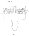
- a known irrigation emitter unit comprises an outer cylindrical member 1 and an inner member 2 having a substantially planar upper surface 3 and through which extends a central outlet port 4.
- the outer member 1 on the other hand, is provided with a coupling nipple 5 by which the emitter unit can be coupled to an irrigation pipe (not shown).
- the outer and inner members are formed of like plastics materials.
- peripheral groove 6 constituting an undercut, and having upper and lower sloping edges.
- the inner member 2 is formed with a peripheral flanged rib 7 which has correspondingly sloping edges. As seen in Fig. 1, when the emitter unit is assembled and the inner member is forced into position as shown, the flanged rib 7 is located within the peripheral groove 6 and is retained therein.
- the shape and mode of location of the flanged rib 7 within the recess 6 are such that the effective retention of the inner member 2 within the outer member 1 cannot always be ensured, especially when a relatively high pressure develops within the emitter unit, in which case the inner member 2 can well be expelled from the outer member 1.
- the formation of the undercut recess 6 with sloping edges is essentially dictated by standard plastic molding technology and the presence of these sloping edges renders the retention of the inner member 2 within the outer member 1 even more difficult.
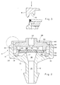
- Fig. 2 of the drawings shows the respective components of an irrigation emitter unit assembled together prior to the final operation designed to ensure the effective sealing retention of the components one within the other.
- the unit comprises an outer member 11 consisting of a substantially cylindrical casing portion 12, a coupling nipple portion 13, the portions 12 and 13 being integrally coupled together via a sloping portion 14.
- the coupling nipple 13 defines a central inlet port 15 which communicates with a central portion of an inlet control chamber 16 formed in the outer member 11.
- the sloping portion 14 is formed integrally with an annular support 17 within which is defined the inlet control chamber 16, the annular support 17 tapering towards a circular apex 18.
- An annular groove 19 is formed in an upper surface of the tapering portion 14 adjacent the inner surface of the cylindrical portion 12.
- the cylindrical portion 12 is formed integrally with an upwardly projecting terminal portion 20 which is of reduced thickness as compared with the remainder of the cylindrical portion 12.
- An inner member 25 comprises an upper, substantially planar annular portion 26 having a central outlet port 27 and being formed with a downwardly depending skirt portion 28, the latter terminating in a bevelled end portion 29 which fits within the annular groove 19.
- the upper portion 26 is formed with an outer peripheral flange 30 having an outer annular surface which fits sealingly against the inner annular surface of the cylindrical portion 12.
- the bevelled end portion 29 is formed with an outer annular surface which fits sealingly against the inner surface of the cylindrical portion 12.
- a flow reducing path 33 Defined between the outer surface of the skirt portion 28 and the inner surface of the cylindrical portion 12 is a flow reducing path 33.
- One end of the flow reducing path 33 communicates with an annular region 34 defined between an inner surface of the skirt portion 28 and an outer surface of the support 17.
- An opposite end of the flow reducing path 33 communicates with an upper region defined within the inner member 25.
- An inwardly directed annular shoulder 35 having an innermost corner 36 is formed on the inner surface of the skirt portion 28.
- a circular flexible membrane 37 is centrally supported at its under surface on the circular tip 18 of the support 17 and, at its outer surface against the circular corner 36 of the shoulder 35.
- the membrane is so supported as to be slightly flexed upwardly.
- the membrane 37 defines, together with the support 17, an inlet control chamber 16 and, with the under surface of the planar portion 26, an outlet control chamber 38.
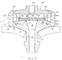
- an ultrasonic distortion is carried out whereby, as shown in Fig. 3 of the drawings, an ultrasonic tip 41, having a suitably shaped annular spherical recess 42, is brought into contact with the upper end portions of the assembled unit and the process of staking results in the melting and reforming of the terminal portion 20 (the melted and re-formed portions being shown in Fig. 3 in hatched lines).
- an ultrasonic tip 41 having a suitably shaped annular spherical recess 42, is brought into contact with the upper end portions of the assembled unit and the process of staking results in the melting and reforming of the terminal portion 20 (the melted and re-formed portions being shown in Fig. 3 in hatched lines).
- the terminal portion 20 has been converted into an inwardly directed peripheral flanged end portion 45 which bears against the terminal peripheral rin 30 and is, in fact, welded to this rib, thereby effectively and sealing retaining the inner portion 26 within the outer portion 11.
- the emitter unit construction just described has the following distinct advantages:
Landscapes
- Engineering & Computer Science (AREA)
- Mechanical Engineering (AREA)
- Life Sciences & Earth Sciences (AREA)
- Soil Sciences (AREA)
- Water Supply & Treatment (AREA)
- Environmental Sciences (AREA)
- Infusion, Injection, And Reservoir Apparatuses (AREA)
- Vehicle Body Suspensions (AREA)
- Paper (AREA)
- Rigid Pipes And Flexible Pipes (AREA)
- Reciprocating Pumps (AREA)
- External Artificial Organs (AREA)
- Nozzles (AREA)
- Surgical Instruments (AREA)
- Fluid-Pressure Circuits (AREA)
Applications Claiming Priority (2)
| Application Number | Priority Date | Filing Date | Title |
|---|---|---|---|
| IL96106A IL96106A (en) | 1990-10-25 | 1990-10-25 | Fluid flow control unit for example for an irrigation emitter |
| IL96106 | 1990-10-25 |
Publications (2)
| Publication Number | Publication Date |
|---|---|
| EP0482843A1 true EP0482843A1 (de) | 1992-04-29 |
| EP0482843B1 EP0482843B1 (de) | 1995-12-13 |
Family
ID=11061703
Family Applications (1)
| Application Number | Title | Priority Date | Filing Date |
|---|---|---|---|
| EP91309662A Expired - Lifetime EP0482843B1 (de) | 1990-10-25 | 1991-10-18 | Verbesserte Flüssigkeitssteuereinheit |
Country Status (11)
| Country | Link |
|---|---|
| US (1) | US5279462A (de) |
| EP (1) | EP0482843B1 (de) |
| AT (1) | ATE131346T1 (de) |
| AU (1) | AU639374B2 (de) |
| BR (1) | BR9104607A (de) |
| DE (1) | DE69115437T2 (de) |
| DK (1) | DK0482843T3 (de) |
| ES (1) | ES2080914T3 (de) |
| GR (1) | GR3019233T3 (de) |
| IL (1) | IL96106A (de) |
| ZA (1) | ZA918378B (de) |
Cited By (7)
| Publication number | Priority date | Publication date | Assignee | Title |
|---|---|---|---|---|
| EP0598676A1 (de) * | 1992-11-19 | 1994-05-25 | PASKAL AVIZAREY KSHIRA Ltd. | Tropfbewässerungsauslass und darin verwendbarer Wasserzapf |
| EP0836531A1 (de) * | 1994-04-29 | 1998-04-22 | Naan Sprinklers And Irrigation Systems, Inc. | Bewässerungsvorrichtung |
| WO2001065844A2 (fr) | 2000-02-25 | 2001-09-07 | Thomson Licensing S.A. | Procede de visualisation d'emissions audiovisuelles diffusees et dispositif de visualisation associe |
| GR20000100065A (el) | 2000-02-28 | 2001-10-31 | Σταλακτης με φιλτρο εισοδου του νερου και μεθοδος συναρμολογησης | |
| EP1884157A1 (de) * | 2006-08-03 | 2008-02-06 | GARDENA Manufacturing GmbH | Bewässerungsvorrichtung |
| CN103062466A (zh) * | 2013-01-11 | 2013-04-24 | 李光永 | 一种微灌毛管进口流量调节器 |
| RU2579468C1 (ru) * | 2014-12-24 | 2016-04-10 | Михаил Иванович Голубенко | Водовыпуск поливного трубопровода |
Families Citing this family (47)
| Publication number | Priority date | Publication date | Assignee | Title |
|---|---|---|---|---|
| US5820028A (en) * | 1992-02-26 | 1998-10-13 | Naan Irrigation Systems | Irrigation apparatus |
| US5634594A (en) * | 1993-07-30 | 1997-06-03 | Cohen; Amir | Flow control device particularly useful in drip irrigation emitters |
| US5636797A (en) * | 1993-07-30 | 1997-06-10 | Cohen; Amir | Drip irrigation emitter and flow control unit included therein |
| US5413282A (en) * | 1993-10-28 | 1995-05-09 | James Hardie Irrigation, Inc. | Pressure compensating emitter with shut down flush |
| US6305617B1 (en) | 1994-05-03 | 2001-10-23 | Michael Yu | Oscillating disk dental hygiene device |
| US5711482A (en) * | 1994-05-03 | 1998-01-27 | Yu; Michael | Resilient disk drip irrigation devices |
| US6085986A (en) * | 1994-05-03 | 2000-07-11 | Yu; Michael | Oscillating disk drives |
| US5615838A (en) * | 1995-03-10 | 1997-04-01 | Drip Irrigation Systems, Ltd. | In-line retention drip emitter |
| IL122777A (en) * | 1997-12-28 | 2003-12-10 | Amir Cohen | Valve controlled drip irrigation lines |
| IL131716A (en) | 1998-12-21 | 2006-09-05 | Amir Cohen | Drip irrigation emitters |
| IL129817A (en) * | 1999-05-06 | 2002-12-01 | Plassim Tech Plastics Works | Method for producing an irrigation pipeline with inner emitters |
| IL134695A0 (en) * | 2000-02-23 | 2001-07-24 | Naan Irrigation Systems C S Lt | Flow regulators with flexibile diaphragms |
| WO2006105364A2 (en) * | 2005-03-31 | 2006-10-05 | Rain Bird Corporation | Drip emitter |
| AU2006281078A1 (en) * | 2005-08-17 | 2007-02-22 | Netafim Ltd. | Foam silicone parts in irrigation emitters |
| IL171482A (en) | 2005-10-19 | 2014-12-31 | Zvi Einav | Dropper with independent runoff valve |
| WO2007074428A1 (en) * | 2005-12-27 | 2007-07-05 | Netafim Ltd. | Fluid flow control regulator |
| US7648085B2 (en) * | 2006-02-22 | 2010-01-19 | Rain Bird Corporation | Drip emitter |
| ITSV20060018A1 (it) * | 2006-07-10 | 2008-01-11 | Irritec S R L | Emettitore regolabile per fluidi in particolare negli impianti di irrigazione |
| US8628032B2 (en) | 2008-12-31 | 2014-01-14 | Rain Bird Corporation | Low flow irrigation emitter |
| IL204685A (en) * | 2009-03-23 | 2014-07-31 | Rosenberg Avner | A device for flow control especially useful for drip irrigation drips |
| US8317111B2 (en) | 2010-01-31 | 2012-11-27 | Amirim Products Development & Patents Ltd. | Bi-component drip emitter |
| GB2484924A (en) | 2010-10-25 | 2012-05-02 | Amirim Products Dev & Patents Ltd | An on line drip irrigation emitter having an inlet filtering dvice |
| US9877440B2 (en) | 2012-03-26 | 2018-01-30 | Rain Bird Corporation | Elastomeric emitter and methods relating to same |
| US20130248622A1 (en) | 2012-03-26 | 2013-09-26 | Jae Yung Kim | Drip line and emitter and methods relating to same |
| US10440903B2 (en) | 2012-03-26 | 2019-10-15 | Rain Bird Corporation | Drip line emitter and methods relating to same |
| US9485923B2 (en) | 2012-03-26 | 2016-11-08 | Rain Bird Corporation | Elastomeric emitter and methods relating to same |
| US9872444B2 (en) | 2013-03-15 | 2018-01-23 | Rain Bird Corporation | Drip emitter |
| US9949448B2 (en) * | 2015-01-14 | 2018-04-24 | Amirim Products Development & Patents Ltd. | Modular in line button drip emitter system |
| US10869434B2 (en) | 2013-07-09 | 2020-12-22 | Amirim Products Development & Patents Ltd. | Elliptical in line button dripper with extended bonding zones |
| US9462760B2 (en) | 2013-07-09 | 2016-10-11 | Amirim Products Development & Patents Ltd. | In line button drip emitter |
| US10631473B2 (en) | 2013-08-12 | 2020-04-28 | Rain Bird Corporation | Elastomeric emitter and methods relating to same |
| US10285342B2 (en) | 2013-08-12 | 2019-05-14 | Rain Bird Corporation | Elastomeric emitter and methods relating to same |
| USD811179S1 (en) | 2013-08-12 | 2018-02-27 | Rain Bird Corporation | Emitter part |
| MX369536B (es) * | 2013-09-25 | 2019-11-11 | Netafim Ltd | Emisor por goteo. |
| US9883640B2 (en) | 2013-10-22 | 2018-02-06 | Rain Bird Corporation | Methods and apparatus for transporting elastomeric emitters and/or manufacturing drip lines |
| WO2015070915A1 (de) | 2013-11-14 | 2015-05-21 | Alfred Kärcher Gmbh & Co. Kg | Sprühdüsenvorrichtung und verfahren zur einstellung eines oder mehrerer sprühstrahlen |
| EP3157681A1 (de) * | 2014-06-20 | 2017-04-26 | Medspray B.V. | Aerosol- oder sprühvorrichtung, sprühdüseneinheit und verfahren zur herstellung davon |
| US10330559B2 (en) | 2014-09-11 | 2019-06-25 | Rain Bird Corporation | Methods and apparatus for checking emitter bonds in an irrigation drip line |
| ES2842898T3 (es) | 2015-12-03 | 2021-07-15 | Netafim Ltd | Emisor de goteo |
| JP6689634B2 (ja) * | 2016-03-17 | 2020-04-28 | 株式会社エンプラス | エミッタおよび点滴灌漑用チューブ |
| IL251621A0 (en) | 2016-04-07 | 2017-06-29 | Cohen Amir | Button dripper for irrigation lines |
| US10375904B2 (en) | 2016-07-18 | 2019-08-13 | Rain Bird Corporation | Emitter locating system and related methods |
| US10100863B2 (en) * | 2016-07-27 | 2018-10-16 | GM Global Technology Operations LLC | External heat-stake arrangement |
| US11051466B2 (en) | 2017-01-27 | 2021-07-06 | Rain Bird Corporation | Pressure compensation members, emitters, drip line and methods relating to same |
| US10626998B2 (en) * | 2017-05-15 | 2020-04-21 | Rain Bird Corporation | Drip emitter with check valve |
| USD883048S1 (en) | 2017-12-12 | 2020-05-05 | Rain Bird Corporation | Emitter part |
| US11985924B2 (en) | 2018-06-11 | 2024-05-21 | Rain Bird Corporation | Emitter outlet, emitter, drip line and methods relating to same |
Citations (5)
| Publication number | Priority date | Publication date | Assignee | Title |
|---|---|---|---|---|
| US3436803A (en) * | 1966-02-07 | 1969-04-08 | Stanley J Sarnoff | Uniting parts by the use of vibrational and positive material deforming forces and article made thereby |
| FR2366790A1 (fr) * | 1976-10-10 | 1978-05-05 | Drori Mordeki | Dispositif d'irrigation goutte-a-goutte et regulateur de pression d'eau pour un tel dispositif |
| EP0024670A2 (de) * | 1979-09-04 | 1981-03-11 | Dan Bron | Selbstregelnde Düse für eine Zuführleitung mit konstantem Durchfluss |
| FR2468810A1 (fr) * | 1979-10-29 | 1981-05-08 | Irrifrance Sa | Limiteur de debit |
| FR2469959A1 (fr) * | 1979-11-22 | 1981-05-29 | Hydro Plan Eng Ltd | Dispositif pour l'emission goutte a goutte de liquide |
Family Cites Families (10)
| Publication number | Priority date | Publication date | Assignee | Title |
|---|---|---|---|---|
| FR48310E (fr) * | 1936-07-31 | 1937-12-27 | Accessoire Precision | Perfectionnements apportés aux dispositifs de commande à distance, notamment à ceux pour véhicules automobiles |
| FR48811E (fr) * | 1937-02-19 | 1938-07-12 | Tube à vide amplificateur | |
| US2431238A (en) * | 1946-04-15 | 1947-11-18 | Friedman Theodore | Process of locking flat members to bodies |
| US3970273A (en) * | 1975-01-10 | 1976-07-20 | Arundale, Inc. | Appliance foot with secure resilient pad |
| US3998427A (en) * | 1975-12-11 | 1976-12-21 | Clarence Bentley | Self-cleaning drip irrigation valve |
| US4084749A (en) * | 1976-04-11 | 1978-04-18 | Mordeki Drori | Flow reducing devices particularly useful as drip emitters for drip irrigation |
| IL50766A (en) * | 1976-10-26 | 1983-06-15 | Hydro Plan Eng Ltd | Irrigation emitter unit |
| DE2729458C3 (de) * | 1977-06-30 | 1981-07-16 | Arcu Armaturindustri AB, Alstermo | Strömungsregulator, insbesondere zum Einbau zwischen einem Wasserkran und einem Wasserleitungsende |
| SU935011A1 (ru) * | 1981-01-19 | 1982-06-15 | Всесоюзное Научно-Производственное Объединение По Механизации Орошения "Радуга" | Водовыпуск дл капельного орошени |
| CA1292846C (en) * | 1988-09-20 | 1991-12-10 | Pierre P. Meunier | Charcoal bed assembly |
-
1990
- 1990-10-25 IL IL96106A patent/IL96106A/en not_active IP Right Cessation
-
1991
- 1991-10-17 US US07/778,565 patent/US5279462A/en not_active Expired - Lifetime
- 1991-10-18 AU AU86003/91A patent/AU639374B2/en not_active Expired
- 1991-10-18 AT AT91309662T patent/ATE131346T1/de not_active IP Right Cessation
- 1991-10-18 EP EP91309662A patent/EP0482843B1/de not_active Expired - Lifetime
- 1991-10-18 DE DE69115437T patent/DE69115437T2/de not_active Expired - Lifetime
- 1991-10-18 ES ES91309662T patent/ES2080914T3/es not_active Expired - Lifetime
- 1991-10-18 DK DK91309662.4T patent/DK0482843T3/da active
- 1991-10-21 ZA ZA918378A patent/ZA918378B/xx unknown
- 1991-10-24 BR BR919104607A patent/BR9104607A/pt not_active IP Right Cessation
-
1996
- 1996-03-06 GR GR960400641T patent/GR3019233T3/el unknown
Patent Citations (5)
| Publication number | Priority date | Publication date | Assignee | Title |
|---|---|---|---|---|
| US3436803A (en) * | 1966-02-07 | 1969-04-08 | Stanley J Sarnoff | Uniting parts by the use of vibrational and positive material deforming forces and article made thereby |
| FR2366790A1 (fr) * | 1976-10-10 | 1978-05-05 | Drori Mordeki | Dispositif d'irrigation goutte-a-goutte et regulateur de pression d'eau pour un tel dispositif |
| EP0024670A2 (de) * | 1979-09-04 | 1981-03-11 | Dan Bron | Selbstregelnde Düse für eine Zuführleitung mit konstantem Durchfluss |
| FR2468810A1 (fr) * | 1979-10-29 | 1981-05-08 | Irrifrance Sa | Limiteur de debit |
| FR2469959A1 (fr) * | 1979-11-22 | 1981-05-29 | Hydro Plan Eng Ltd | Dispositif pour l'emission goutte a goutte de liquide |
Cited By (9)
| Publication number | Priority date | Publication date | Assignee | Title |
|---|---|---|---|---|
| EP0598676A1 (de) * | 1992-11-19 | 1994-05-25 | PASKAL AVIZAREY KSHIRA Ltd. | Tropfbewässerungsauslass und darin verwendbarer Wasserzapf |
| EP0836531A1 (de) * | 1994-04-29 | 1998-04-22 | Naan Sprinklers And Irrigation Systems, Inc. | Bewässerungsvorrichtung |
| EP0836531A4 (de) * | 1994-04-29 | 1998-04-22 | ||
| WO2001065844A2 (fr) | 2000-02-25 | 2001-09-07 | Thomson Licensing S.A. | Procede de visualisation d'emissions audiovisuelles diffusees et dispositif de visualisation associe |
| GR20000100065A (el) | 2000-02-28 | 2001-10-31 | Σταλακτης με φιλτρο εισοδου του νερου και μεθοδος συναρμολογησης | |
| EP1884157A1 (de) * | 2006-08-03 | 2008-02-06 | GARDENA Manufacturing GmbH | Bewässerungsvorrichtung |
| CN103062466A (zh) * | 2013-01-11 | 2013-04-24 | 李光永 | 一种微灌毛管进口流量调节器 |
| CN103062466B (zh) * | 2013-01-11 | 2014-11-05 | 李光永 | 一种微灌毛管进口流量调节器 |
| RU2579468C1 (ru) * | 2014-12-24 | 2016-04-10 | Михаил Иванович Голубенко | Водовыпуск поливного трубопровода |
Also Published As
| Publication number | Publication date |
|---|---|
| DE69115437T2 (de) | 1996-05-02 |
| IL96106A0 (en) | 1991-07-18 |
| BR9104607A (pt) | 1992-06-09 |
| AU639374B2 (en) | 1993-07-22 |
| GR3019233T3 (en) | 1996-06-30 |
| DK0482843T3 (da) | 1996-03-04 |
| ES2080914T3 (es) | 1996-02-16 |
| AU8600391A (en) | 1992-04-30 |
| DE69115437D1 (de) | 1996-01-25 |
| ZA918378B (en) | 1992-07-29 |
| ATE131346T1 (de) | 1995-12-15 |
| IL96106A (en) | 1998-04-05 |
| US5279462A (en) | 1994-01-18 |
| EP0482843B1 (de) | 1995-12-13 |
Similar Documents
| Publication | Publication Date | Title |
|---|---|---|
| EP0482843A1 (de) | Verbesserte Flüssigkeitssteuereinheit | |
| US4366926A (en) | Irrigation emitter unit | |
| US5771935A (en) | Check valve, especially for the medical technique | |
| JP3266356B2 (ja) | 逆止弁 | |
| US4281798A (en) | Drip or trickle emitter | |
| US5857595A (en) | Self-closing apparatus | |
| EP0191969B1 (de) | Ventilvorrichtung | |
| US4624286A (en) | Degasifying valve for containers | |
| JP5575464B2 (ja) | カートリッジピストン | |
| US20170290277A1 (en) | In line button drip emitter | |
| CA1271105A (en) | Valve for relieving pressure or checking reverse flow | |
| CN101291854B (zh) | 反渗透成品水贮存罐和反渗透系统中的方法 | |
| JP2009530202A (ja) | 液体注出栓,特に高密度液体用の注出栓 | |
| EP0854311A2 (de) | Flüssigkeitsrückschlagventil | |
| US6942194B2 (en) | Gate valve | |
| JPS584230B2 (ja) | 圧力導管用の連結装置 | |
| GB2123094A (en) | Flexible-bag self-closing metering dispensing valve | |
| US6685063B2 (en) | Cartridge plunger with gas evacuation | |
| CN101437728A (zh) | 具有阀盖的自关闭阀 | |
| WO1997042438A1 (en) | A diaphragm valve | |
| US6481600B2 (en) | Dropper assembly | |
| AU8858698A (en) | Duckbill valve | |
| JP3373491B2 (ja) | バルブユニット及び容器 | |
| US5219149A (en) | Valves for fluid passage | |
| JP6843148B2 (ja) | 流量計 |
Legal Events
| Date | Code | Title | Description |
|---|---|---|---|
| PUAI | Public reference made under article 153(3) epc to a published international application that has entered the european phase |
Free format text: ORIGINAL CODE: 0009012 |
|
| AK | Designated contracting states |
Kind code of ref document: A1 Designated state(s): AT BE CH DE DK ES FR GB GR IT LI LU NL SE |
|
| 17P | Request for examination filed |
Effective date: 19921012 |
|
| 17Q | First examination report despatched |
Effective date: 19931111 |
|
| GRAA | (expected) grant |
Free format text: ORIGINAL CODE: 0009210 |
|
| AK | Designated contracting states |
Kind code of ref document: B1 Designated state(s): AT BE CH DE DK ES FR GB GR IT LI LU NL SE |
|
| REF | Corresponds to: |
Ref document number: 131346 Country of ref document: AT Date of ref document: 19951215 Kind code of ref document: T |
|
| ITF | It: translation for a ep patent filed |
Owner name: JACOBACCI & PERANI S.P.A. |
|
| REF | Corresponds to: |
Ref document number: 69115437 Country of ref document: DE Date of ref document: 19960125 |
|
| REG | Reference to a national code |
Ref country code: CH Ref legal event code: NV Representative=s name: A. BRAUN, BRAUN, HERITIER, ESCHMANN AG PATENTANWAE |
|
| REG | Reference to a national code |
Ref country code: ES Ref legal event code: FG2A Ref document number: 2080914 Country of ref document: ES Kind code of ref document: T3 |
|
| REG | Reference to a national code |
Ref country code: DK Ref legal event code: T3 |
|
| ET | Fr: translation filed | ||
| REG | Reference to a national code |
Ref country code: GR Ref legal event code: FG4A Free format text: 3019233 |
|
| PG25 | Lapsed in a contracting state [announced via postgrant information from national office to epo] |
Ref country code: AT Effective date: 19961018 |
|
| PLBE | No opposition filed within time limit |
Free format text: ORIGINAL CODE: 0009261 |
|
| STAA | Information on the status of an ep patent application or granted ep patent |
Free format text: STATUS: NO OPPOSITION FILED WITHIN TIME LIMIT |
|
| PG25 | Lapsed in a contracting state [announced via postgrant information from national office to epo] |
Ref country code: SE Effective date: 19961019 |
|
| PG25 | Lapsed in a contracting state [announced via postgrant information from national office to epo] |
Ref country code: CH Effective date: 19961031 Ref country code: BE Effective date: 19961031 Ref country code: LU Free format text: LAPSE BECAUSE OF NON-PAYMENT OF DUE FEES Effective date: 19961031 Ref country code: LI Effective date: 19961031 |
|
| 26N | No opposition filed | ||
| BERE | Be: lapsed |
Owner name: HYDROPLAN ENGINEERING LTD Effective date: 19961031 |
|
| REG | Reference to a national code |
Ref country code: CH Ref legal event code: PL |
|
| EUG | Se: european patent has lapsed |
Ref document number: 91309662.4 |
|
| REG | Reference to a national code |
Ref country code: GB Ref legal event code: IF02 |
|
| PGFP | Annual fee paid to national office [announced via postgrant information from national office to epo] |
Ref country code: DK Payment date: 20101028 Year of fee payment: 20 Ref country code: FR Payment date: 20101104 Year of fee payment: 20 Ref country code: NL Payment date: 20101029 Year of fee payment: 20 |
|
| PGFP | Annual fee paid to national office [announced via postgrant information from national office to epo] |
Ref country code: IT Payment date: 20101030 Year of fee payment: 20 Ref country code: GB Payment date: 20101029 Year of fee payment: 20 Ref country code: GR Payment date: 20101101 Year of fee payment: 20 |
|
| PGFP | Annual fee paid to national office [announced via postgrant information from national office to epo] |
Ref country code: DE Payment date: 20101227 Year of fee payment: 20 |
|
| PGFP | Annual fee paid to national office [announced via postgrant information from national office to epo] |
Ref country code: ES Payment date: 20101126 Year of fee payment: 20 |
|
| REG | Reference to a national code |
Ref country code: DE Ref legal event code: R071 Ref document number: 69115437 Country of ref document: DE |
|
| REG | Reference to a national code |
Ref country code: DE Ref legal event code: R071 Ref document number: 69115437 Country of ref document: DE |
|
| REG | Reference to a national code |
Ref country code: NL Ref legal event code: V4 Effective date: 20111018 |
|
| REG | Reference to a national code |
Ref country code: DK Ref legal event code: EUP |
|
| REG | Reference to a national code |
Ref country code: GB Ref legal event code: PE20 Expiry date: 20111017 |
|
| REG | Reference to a national code |
Ref country code: ES Ref legal event code: FD2A Effective date: 20120110 |
|
| REG | Reference to a national code |
Ref country code: GR Ref legal event code: MA Ref document number: 960400641 Country of ref document: GR Effective date: 20111019 |
|
| PG25 | Lapsed in a contracting state [announced via postgrant information from national office to epo] |
Ref country code: NL Free format text: LAPSE BECAUSE OF EXPIRATION OF PROTECTION Effective date: 20111018 Ref country code: ES Free format text: LAPSE BECAUSE OF EXPIRATION OF PROTECTION Effective date: 20111019 |
|
| PG25 | Lapsed in a contracting state [announced via postgrant information from national office to epo] |
Ref country code: GB Free format text: LAPSE BECAUSE OF EXPIRATION OF PROTECTION Effective date: 20111017 |
|
| PG25 | Lapsed in a contracting state [announced via postgrant information from national office to epo] |
Ref country code: DE Free format text: LAPSE BECAUSE OF EXPIRATION OF PROTECTION Effective date: 20111019 |