EP0482704A1 - Oxide cathode - Google Patents
Oxide cathode Download PDFInfo
- Publication number
- EP0482704A1 EP0482704A1 EP91202695A EP91202695A EP0482704A1 EP 0482704 A1 EP0482704 A1 EP 0482704A1 EP 91202695 A EP91202695 A EP 91202695A EP 91202695 A EP91202695 A EP 91202695A EP 0482704 A1 EP0482704 A1 EP 0482704A1
- Authority
- EP
- European Patent Office
- Prior art keywords
- earth metal
- cathode
- rare earth
- layer
- electron
- Prior art date
- Legal status (The legal status is an assumption and is not a legal conclusion. Google has not performed a legal analysis and makes no representation as to the accuracy of the status listed.)
- Granted
Links
- 150000002910 rare earth metals Chemical class 0.000 claims abstract description 21
- 229910052761 rare earth metal Inorganic materials 0.000 claims abstract description 13
- 239000000463 material Substances 0.000 claims description 17
- QVQLCTNNEUAWMS-UHFFFAOYSA-N barium oxide Chemical compound [Ba]=O QVQLCTNNEUAWMS-UHFFFAOYSA-N 0.000 claims description 10
- VWQVUPCCIRVNHF-UHFFFAOYSA-N yttrium atom Chemical group [Y] VWQVUPCCIRVNHF-UHFFFAOYSA-N 0.000 claims description 10
- IATRAKWUXMZMIY-UHFFFAOYSA-N strontium oxide Chemical compound [O-2].[Sr+2] IATRAKWUXMZMIY-UHFFFAOYSA-N 0.000 claims description 8
- PXHVJJICTQNCMI-UHFFFAOYSA-N Nickel Chemical compound [Ni] PXHVJJICTQNCMI-UHFFFAOYSA-N 0.000 claims description 6
- BVKZGUZCCUSVTD-UHFFFAOYSA-L Carbonate Chemical compound [O-]C([O-])=O BVKZGUZCCUSVTD-UHFFFAOYSA-L 0.000 claims description 5
- OGPBJKLSAFTDLK-UHFFFAOYSA-N europium atom Chemical group [Eu] OGPBJKLSAFTDLK-UHFFFAOYSA-N 0.000 claims description 5
- 150000001342 alkaline earth metals Chemical group 0.000 claims description 4
- 229910052788 barium Inorganic materials 0.000 claims description 4
- DSAJWYNOEDNPEQ-UHFFFAOYSA-N barium atom Chemical compound [Ba] DSAJWYNOEDNPEQ-UHFFFAOYSA-N 0.000 claims description 4
- 150000001875 compounds Chemical class 0.000 claims description 4
- 238000004519 manufacturing process Methods 0.000 claims description 4
- 229910000287 alkaline earth metal oxide Inorganic materials 0.000 claims description 3
- 229910052759 nickel Inorganic materials 0.000 claims description 3
- 238000000354 decomposition reaction Methods 0.000 claims description 2
- 238000010894 electron beam technology Methods 0.000 claims description 2
- 238000000034 method Methods 0.000 claims description 2
- 238000007792 addition Methods 0.000 description 10
- 230000007423 decrease Effects 0.000 description 10
- 229910052727 yttrium Inorganic materials 0.000 description 8
- 239000000203 mixture Substances 0.000 description 4
- PNEYBMLMFCGWSK-UHFFFAOYSA-N Alumina Chemical compound [O-2].[O-2].[O-2].[Al+3].[Al+3] PNEYBMLMFCGWSK-UHFFFAOYSA-N 0.000 description 3
- 229910052693 Europium Inorganic materials 0.000 description 3
- 229910052751 metal Inorganic materials 0.000 description 3
- 239000002184 metal Substances 0.000 description 3
- 239000002245 particle Substances 0.000 description 3
- 239000000243 solution Substances 0.000 description 3
- 238000009827 uniform distribution Methods 0.000 description 3
- WFDIJRYMOXRFFG-UHFFFAOYSA-N Acetic anhydride Chemical compound CC(=O)OC(C)=O WFDIJRYMOXRFFG-UHFFFAOYSA-N 0.000 description 2
- CDBYLPFSWZWCQE-UHFFFAOYSA-L Sodium Carbonate Chemical compound [Na+].[Na+].[O-]C([O-])=O CDBYLPFSWZWCQE-UHFFFAOYSA-L 0.000 description 2
- 229910052784 alkaline earth metal Inorganic materials 0.000 description 2
- IWOUKMZUPDVPGQ-UHFFFAOYSA-N barium nitrate Chemical compound [Ba+2].[O-][N+]([O-])=O.[O-][N+]([O-])=O IWOUKMZUPDVPGQ-UHFFFAOYSA-N 0.000 description 2
- 239000011230 binding agent Substances 0.000 description 2
- BRPQOXSCLDDYGP-UHFFFAOYSA-N calcium oxide Chemical compound [O-2].[Ca+2] BRPQOXSCLDDYGP-UHFFFAOYSA-N 0.000 description 2
- ODINCKMPIJJUCX-UHFFFAOYSA-N calcium oxide Inorganic materials [Ca]=O ODINCKMPIJJUCX-UHFFFAOYSA-N 0.000 description 2
- 239000000292 calcium oxide Substances 0.000 description 2
- 150000004649 carbonic acid derivatives Chemical class 0.000 description 2
- 238000009826 distribution Methods 0.000 description 2
- 238000001035 drying Methods 0.000 description 2
- 229910052747 lanthanoid Inorganic materials 0.000 description 2
- 150000002602 lanthanoids Chemical class 0.000 description 2
- 238000005259 measurement Methods 0.000 description 2
- 150000002739 metals Chemical class 0.000 description 2
- 229910001404 rare earth metal oxide Inorganic materials 0.000 description 2
- DHEQXMRUPNDRPG-UHFFFAOYSA-N strontium nitrate Chemical compound [Sr+2].[O-][N+]([O-])=O.[O-][N+]([O-])=O DHEQXMRUPNDRPG-UHFFFAOYSA-N 0.000 description 2
- 239000000725 suspension Substances 0.000 description 2
- NGDQQLAVJWUYSF-UHFFFAOYSA-N 4-methyl-2-phenyl-1,3-thiazole-5-sulfonyl chloride Chemical compound S1C(S(Cl)(=O)=O)=C(C)N=C1C1=CC=CC=C1 NGDQQLAVJWUYSF-UHFFFAOYSA-N 0.000 description 1
- 229910052684 Cerium Inorganic materials 0.000 description 1
- OIFBSDVPJOWBCH-UHFFFAOYSA-N Diethyl carbonate Chemical compound CCOC(=O)OCC OIFBSDVPJOWBCH-UHFFFAOYSA-N 0.000 description 1
- FYYHWMGAXLPEAU-UHFFFAOYSA-N Magnesium Chemical compound [Mg] FYYHWMGAXLPEAU-UHFFFAOYSA-N 0.000 description 1
- 239000000020 Nitrocellulose Substances 0.000 description 1
- XUIMIQQOPSSXEZ-UHFFFAOYSA-N Silicon Chemical compound [Si] XUIMIQQOPSSXEZ-UHFFFAOYSA-N 0.000 description 1
- FJWGYAHXMCUOOM-QHOUIDNNSA-N [(2s,3r,4s,5r,6r)-2-[(2r,3r,4s,5r,6s)-4,5-dinitrooxy-2-(nitrooxymethyl)-6-[(2r,3r,4s,5r,6s)-4,5,6-trinitrooxy-2-(nitrooxymethyl)oxan-3-yl]oxyoxan-3-yl]oxy-3,5-dinitrooxy-6-(nitrooxymethyl)oxan-4-yl] nitrate Chemical compound O([C@@H]1O[C@@H]([C@H]([C@H](O[N+]([O-])=O)[C@H]1O[N+]([O-])=O)O[C@H]1[C@@H]([C@@H](O[N+]([O-])=O)[C@H](O[N+]([O-])=O)[C@@H](CO[N+]([O-])=O)O1)O[N+]([O-])=O)CO[N+](=O)[O-])[C@@H]1[C@@H](CO[N+]([O-])=O)O[C@@H](O[N+]([O-])=O)[C@H](O[N+]([O-])=O)[C@H]1O[N+]([O-])=O FJWGYAHXMCUOOM-QHOUIDNNSA-N 0.000 description 1
- 230000004913 activation Effects 0.000 description 1
- 239000004411 aluminium Substances 0.000 description 1
- 229910052782 aluminium Inorganic materials 0.000 description 1
- XAGFODPZIPBFFR-UHFFFAOYSA-N aluminium Chemical compound [Al] XAGFODPZIPBFFR-UHFFFAOYSA-N 0.000 description 1
- 239000007864 aqueous solution Substances 0.000 description 1
- ZMIGMASIKSOYAM-UHFFFAOYSA-N cerium Chemical compound [Ce][Ce][Ce][Ce][Ce][Ce][Ce][Ce][Ce][Ce][Ce][Ce][Ce][Ce][Ce][Ce][Ce][Ce][Ce][Ce][Ce][Ce][Ce][Ce][Ce][Ce][Ce][Ce][Ce][Ce][Ce][Ce][Ce][Ce][Ce][Ce][Ce][Ce] ZMIGMASIKSOYAM-UHFFFAOYSA-N 0.000 description 1
- 238000000975 co-precipitation Methods 0.000 description 1
- 238000000151 deposition Methods 0.000 description 1
- 230000002349 favourable effect Effects 0.000 description 1
- 238000001914 filtration Methods 0.000 description 1
- 239000007789 gas Substances 0.000 description 1
- 238000010438 heat treatment Methods 0.000 description 1
- 229910052749 magnesium Inorganic materials 0.000 description 1
- 239000011777 magnesium Substances 0.000 description 1
- WPBNNNQJVZRUHP-UHFFFAOYSA-L manganese(2+);methyl n-[[2-(methoxycarbonylcarbamothioylamino)phenyl]carbamothioyl]carbamate;n-[2-(sulfidocarbothioylamino)ethyl]carbamodithioate Chemical compound [Mn+2].[S-]C(=S)NCCNC([S-])=S.COC(=O)NC(=S)NC1=CC=CC=C1NC(=S)NC(=O)OC WPBNNNQJVZRUHP-UHFFFAOYSA-L 0.000 description 1
- 229910001120 nichrome Inorganic materials 0.000 description 1
- 229920001220 nitrocellulos Polymers 0.000 description 1
- 150000003891 oxalate salts Chemical class 0.000 description 1
- 239000000843 powder Substances 0.000 description 1
- 229910052706 scandium Inorganic materials 0.000 description 1
- SIXSYDAISGFNSX-UHFFFAOYSA-N scandium atom Chemical compound [Sc] SIXSYDAISGFNSX-UHFFFAOYSA-N 0.000 description 1
- 229910052710 silicon Inorganic materials 0.000 description 1
- 239000010703 silicon Substances 0.000 description 1
- 229910000029 sodium carbonate Inorganic materials 0.000 description 1
- ZACXAIOBZQZKCM-UHFFFAOYSA-L strontium;barium(2+);yttrium(3+);carbonate Chemical compound [Sr+2].[Y+3].[Ba+2].[O-]C([O-])=O ZACXAIOBZQZKCM-UHFFFAOYSA-L 0.000 description 1
- 238000007669 thermal treatment Methods 0.000 description 1
- WFKWXMTUELFFGS-UHFFFAOYSA-N tungsten Chemical compound [W] WFKWXMTUELFFGS-UHFFFAOYSA-N 0.000 description 1
- 229910052721 tungsten Inorganic materials 0.000 description 1
- 239000010937 tungsten Substances 0.000 description 1
- 238000005406 washing Methods 0.000 description 1
- XLYOFNOQVPJJNP-UHFFFAOYSA-N water Substances O XLYOFNOQVPJJNP-UHFFFAOYSA-N 0.000 description 1
Images
Classifications
-
- H—ELECTRICITY
- H01—ELECTRIC ELEMENTS
- H01J—ELECTRIC DISCHARGE TUBES OR DISCHARGE LAMPS
- H01J1/00—Details of electrodes, of magnetic control means, of screens, or of the mounting or spacing thereof, common to two or more basic types of discharge tubes or lamps
- H01J1/02—Main electrodes
- H01J1/13—Solid thermionic cathodes
- H01J1/14—Solid thermionic cathodes characterised by the material
- H01J1/142—Solid thermionic cathodes characterised by the material with alkaline-earth metal oxides, or such oxides used in conjunction with reducing agents, as an emissive material
Definitions
- the invention relates to a cathode having a supporting body substantially comprising nickel and being coated with a layer of electron-emissive material comprising alkaline earth metal oxides and comprising at least barium and a rare earth metal.
- the invention also relates to a method of manufacturing such a cathode, and to an electron beam tube provided with a cathode according to the invention.
- Such cathodes are described, for example, in EP-A-0,210,805.
- the emission of such cathodes is based on the release of barium from barium oxide.
- the electron-emissive material usually comprises strontium oxide and sometimes calcium oxide.
- Improved electron emission properties are obtained by the addition of rare earth metals.
- EP-A-0,210,805 teaches that the addition of rare earth metals should be at least 0.05% by weight to obtain at least some improvement of the emission.
- sites small areas having the lowest effective electron work function, which sites are spread over the electron-emissive material.
- sites having a slightly higher work function will hardly contribute to the electron current generated by the cathode.
- a cathode according to the invention is therefore characterized in that the number of rare earth metal atoms in the electron-emissive material as a fraction of the number of alkaline earth metal atoms is 10-500 ppm and in that the rare earth metal atoms are distributed substantially uniformly over at least the upper part of the layer of emissive material.
- the layer of electron-emissive material is obtained by decomposition of a co-precipitated alkaline earth metal-rare earth metal compound.
- rare earth metals are not only understood to mean the metals of the lanthanides but also the metals yttrium and scandium.
- distributed substantially uniformly is understood to mean that each one of the separate particles of alkaline earth metal oxides in the layer of emissive material comprises rare earth metal atoms.
- a carbonate is preferably used for the alkaline earth metal-rare earth metal compound, but, for example, oxalates or formiates are alternatively possible.
- the invention is based, inter alia, on the recognition that the uniform distribution of the rare earth metals leads to a uniform distribution of the number of sites. It is found that better cathode properties (higher emission, longer lifetime, etc.) are obtained when using smaller quantities of yttrium, seandium or one of the lanthanides than in cathodes without additions. Notably, additions of yttrium or europium yield good results.
- a cathode according to the invention may have a decrease of the emission which is comparable to or even larger than that of a cathode in accordance with EP-A-0,210,805 with 2.5% by weight of Y 2 0 3 in the emissive layer, but it may have further lifetime properties which are so much better that it is to be preferred for use in an electron tube. Moreover, said advantages of a better resistance to processing and use of fewer rare earth metals remain valid.
- a method of manufacturing a cathode according to the invention is characterized in that a mixture of rare earth alkaline compounds is provided on the supporting body, in which the number of rare earth metal atoms as a fraction of the number of alkaline earth metal atoms is 10-500 ppm.
- the cathode 1 in Fig. 1 has a cylindrical nichrome cathode shaft 3 provided with a cap 7 in this embodiment.
- the cap 7 substantially comprises nickel and may comprise reducing means such as, for example, silicon, magnesium, manganese, aluminium and tungsten.
- the cathode shaft 3 accommodates a helical filament 4 which comprises a metal helically wound core 5 and an electrically insulating aluminium oxide layer 6.
- An approximately 70 ⁇ m thick layer of emissive material 2 is present on the cap 7, which layer comprises, for example, a mixture of barium oxide, strontium oxide and a rare earth oxide obtained by providing and subsequently decomposing a co-precipitated barium strontium-rare earth carbonate, or a mixture of barium oxide, strontium oxide, calcium oxide and a rare earth oxide.
- a carbonate comprising 60 ppm of yttrium (as a fraction of the number of alkaline earth metal atoms) was obtained by dissolving 20.1 kg of barium nitrate and 16.5 kg of strontium nitrate in 160 ml of water and by heating this mixture to 88 C, together with 16.4 ml of an yttrium nitrate solution which comprised 50 mg of yttrium/litre.
- An aqueous solution comprising 18 kg of sodium carbonate was subsequently added thereto at a rate of 1.1 litre/minute so that a completely co-precipitated barium strontium yttrium carbonate was obtained.
- the carbonate thus obtained was subsequently filtered, washed and dried.
- the desired suspension was obtained by adding 2 litres of a binder solution (diethyl carbonate to which a small quantity of binder material (cellulose nitrate) is added) to 1.1 kg of the co-precipitated carbonate.
- a binder solution diethyl carbonate to which a small quantity of binder material (cellulose nitrate) is added
- suspensions were prepared which comprised 300 ppm of europium.
- Cathodes having an emissive layer of this type of carbonates comprising 60 ppm of yttrium atoms 300 ppm of europium atoms, respectively, (as a fraction of the alkaline earth metal atoms) were mounted in a cathode ray tube.
- the cathode ray tubes were operated for 2000 hours at a filament voltage of 7 Volts, which is comparable with approximately 10,000 real operating hours.
- emission measurements were performed at a filament voltage of 7 Volts after 30 seconds of conveying current at a cathode load of 2.2 A /cm 2 (referred to as Ai k , 30 measurement).
- the decrease in emission current was 2% when yttrium was added and approximately 5% when europium was added, while this decrease was 24% in the case without any additions. Moreover, the initial emission in all cases was found to be approximately 3% higher than in cathodes without any additions.
- the cathode with 60 ppm of Y atoms has better lifetime properties than the cathode with 2.5% by weight of Y 2 0 3 and is by far better than a cathode without additions.
- the cathode with 300 ppm of Eu has a slightly poorer lifetime behaviour, it has all the advantages of a better resistance and less use of material (rare earth metals).
- the cathode may be designed in various manners (cylindrical, concave, convex, etc.) and there are various methods of providing the electron-emissive layer.
- This layer with the uniform distribution of the rare earth metals can also be obtained by depositing Ba-Sr-carbonade particles in a solution comprising yttrium (for example, an acetyl acetate) and by subsequent drying, with yttrium being left on each particle. By filtering, washing and drying an emissive material can then be obtained again with the powder thus obtained.
Landscapes
- Solid Thermionic Cathode (AREA)
Abstract
Description
- The invention relates to a cathode having a supporting body substantially comprising nickel and being coated with a layer of electron-emissive material comprising alkaline earth metal oxides and comprising at least barium and a rare earth metal.
- The invention also relates to a method of manufacturing such a cathode, and to an electron beam tube provided with a cathode according to the invention.
- Such cathodes are described, for example, in EP-A-0,210,805. The emission of such cathodes is based on the release of barium from barium oxide. In addition to the barium oxide the electron-emissive material usually comprises strontium oxide and sometimes calcium oxide. Improved electron emission properties are obtained by the addition of rare earth metals. EP-A-0,210,805 teaches that the addition of rare earth metals should be at least 0.05% by weight to obtain at least some improvement of the emission.
- The actual emission is mainly ensured by small areas (so-called "sites") having the lowest effective electron work function, which sites are spread over the electron-emissive material. In practice sites having a slightly higher work function will hardly contribute to the electron current generated by the cathode.
- For a high effective electron emission it is therefore favourable to choose the number of sites having a minimal work function and the distribution of the sites over the emissive layer as optimally as possible.
- It is one of the objects of the invention to realize such an optimum distribution in a cathode of the type mentioned in the opening paragraph with minimal additions of rare earth metals. It is another object of the invention to provide such a cathode which is well resistant to various manufacturing steps when it is being built into an electron tube, and which has a long lifetime.
- A cathode according to the invention is therefore characterized in that the number of rare earth metal atoms in the electron-emissive material as a fraction of the number of alkaline earth metal atoms is 10-500 ppm and in that the rare earth metal atoms are distributed substantially uniformly over at least the upper part of the layer of emissive material.
- In a preferred embodiment the layer of electron-emissive material is obtained by decomposition of a co-precipitated alkaline earth metal-rare earth metal compound.
- In this respect it is to be noted that rare earth metals are not only understood to mean the metals of the lanthanides but also the metals yttrium and scandium. In this connection "distributed substantially uniformly" is understood to mean that each one of the separate particles of alkaline earth metal oxides in the layer of emissive material comprises rare earth metal atoms.
- It is further to be noted that the provision of, for example, cerium in an emissive layer by means of coprecipitation is known per se from JP-A-74/12758. However, much larger quantities are concerned than in the present invention, viz. quantities within the range mentioned in EP-A-0,210,805.
- A carbonate is preferably used for the alkaline earth metal-rare earth metal compound, but, for example, oxalates or formiates are alternatively possible.
- The invention is based, inter alia, on the recognition that the uniform distribution of the rare earth metals leads to a uniform distribution of the number of sites. It is found that better cathode properties (higher emission, longer lifetime, etc.) are obtained when using smaller quantities of yttrium, seandium or one of the lanthanides than in cathodes without additions. Notably, additions of yttrium or europium yield good results.
- Said lifetime improvement need not always become manifest in a reduced rate of the decrease of the emission, but may also become manifest in a less repid decrease of other properties which are important for the lifetime, such as, for example, the cut-off voltage. For example, a cathode according to the invention may have a decrease of the emission which is comparable to or even larger than that of a cathode in accordance with EP-A-0,210,805 with 2.5% by weight of Y203 in the emissive layer, but it may have further lifetime properties which are so much better that it is to be preferred for use in an electron tube. Moreover, said advantages of a better resistance to processing and use of fewer rare earth metals remain valid.
- A method of manufacturing a cathode according to the invention is characterized in that a mixture of rare earth alkaline compounds is provided on the supporting body, in which the number of rare earth metal atoms as a fraction of the number of alkaline earth metal atoms is 10-500 ppm.
- The invention will now be described in greater detail with reference to an embodiment and the drawing in which
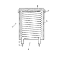
- Fig. 1 is a diagrammatic cross-sectional view of a cathode according to the invention.
- The cathode 1 in Fig. 1 has a cylindrical nichrome cathode shaft 3 provided with a cap 7 in this embodiment. The cap 7 substantially comprises nickel and may comprise reducing means such as, for example, silicon, magnesium, manganese, aluminium and tungsten. The cathode shaft 3 accommodates a helical filament 4 which comprises a metal helically wound core 5 and an electrically insulating aluminium oxide layer 6.
- An approximately 70 µm thick layer of
emissive material 2 is present on the cap 7, which layer comprises, for example, a mixture of barium oxide, strontium oxide and a rare earth oxide obtained by providing and subsequently decomposing a co-precipitated barium strontium-rare earth carbonate, or a mixture of barium oxide, strontium oxide, calcium oxide and a rare earth oxide. - A carbonate comprising 60 ppm of yttrium (as a fraction of the number of alkaline earth metal atoms) was obtained by dissolving 20.1 kg of barium nitrate and 16.5 kg of strontium nitrate in 160 ml of water and by heating this mixture to 88 C, together with 16.4 ml of an yttrium nitrate solution which comprised 50 mg of yttrium/litre. An aqueous solution comprising 18 kg of sodium carbonate was subsequently added thereto at a rate of 1.1 litre/minute so that a completely co-precipitated barium strontium yttrium carbonate was obtained. The carbonate thus obtained was subsequently filtered, washed and dried.
- The desired suspension was obtained by adding 2 litres of a binder solution (diethyl carbonate to which a small quantity of binder material (cellulose nitrate) is added) to 1.1 kg of the co-precipitated carbonate.
- Similarly, suspensions were prepared which comprised 300 ppm of europium.
- Cathodes having an emissive layer of this type of carbonates comprising 60 ppm of yttrium atoms 300 ppm of europium atoms, respectively, (as a fraction of the alkaline earth metal atoms) were mounted in a cathode ray tube.
- After this standard mounting and activation of the cathodes in the tube, with the carbonates decomposing to oxides, the cathode ray tubes were operated for 2000 hours at a filament voltage of 7 Volts, which is comparable with approximately 10,000 real operating hours. Before and after this life test emission measurements were performed at a filament voltage of 7 Volts after 30 seconds of conveying current at a cathode load of 2.2A/cm2 (referred to as Aik,30 measurement).
- The decrease in emission current was 2% when yttrium was added and approximately 5% when europium was added, while this decrease was 24% in the case without any additions. Moreover, the initial emission in all cases was found to be approximately 3% higher than in cathodes without any additions.
- Also other properties such as, for example, the resistance to gases and a thermal treatment of the tube were found to be considerably better.
- The above-mentioned values of Aik (decrease of emission current) are stated in Table I, as well as the decrease of the cut-off voltage (AVk) and the slump (i.e. a measure of the emission current decrease). The Table also states the values for a cathode in accordance with EP-A-0,210,805 with 2.5% by weight of Y203 and for a cathode without additions.

- It is apparent from the Table that in all respects the cathode with 60 ppm of Y atoms has better lifetime properties than the cathode with 2.5% by weight of Y203 and is by far better than a cathode without additions. Although the cathode with 300 ppm of Eu has a slightly poorer lifetime behaviour, it has all the advantages of a better resistance and less use of material (rare earth metals).
- Similar lifetime tests as described hereinbefore were performed in other types of cathode ray tubes with cathodes in accordance with the invention in which 10 ppm of Eu, 60 ppm of Eu, 20 ppm of Y, 60 ppm of Y and 500 ppm of Y had been added to the emissive layer. The results are stated in Table II.

- It is apparent from Table II that for small quantities (10-20 ppm) of rare earth metal atoms the emission decreases to a greater extent than in a cathode with 60 ppm of Y, but notably AVk is much lower (under identical circumstances). Similar remarks as for the cathode with 300 ppm of Eu in Table 1 apply to the cathode with 500 ppm of Y.
- In the latter series of tests one cathode was also tested which had an emissive layer consisting of a 40 /1.m thick layer without additions while on top of it a 20 µm thick layer was provided to which 60 ppm of Y atoms had been added in a uniformly distributed manner. The comparable values of Aik were 10%, 2% and 1.8%, respectively, so that also in this case notably the low decrease of the cut-off voltage leads to a long lifetime.
- The invention is of course not limited to the embodiments shown, but several variations are possible. For example, the cathode may be designed in various manners (cylindrical, concave, convex, etc.) and there are various methods of providing the electron-emissive layer. This layer with the uniform distribution of the rare earth metals can also be obtained by depositing Ba-Sr-carbonade particles in a solution comprising yttrium (for example, an acetyl acetate) and by subsequent drying, with yttrium being left on each particle. By filtering, washing and drying an emissive material can then be obtained again with the powder thus obtained.
Claims (10)
Applications Claiming Priority (2)
| Application Number | Priority Date | Filing Date | Title |
|---|---|---|---|
| NL9002291 | 1990-10-22 | ||
| NL9002291A NL9002291A (en) | 1990-10-22 | 1990-10-22 | OXIDE CATHODE. |
Publications (2)
| Publication Number | Publication Date |
|---|---|
| EP0482704A1 true EP0482704A1 (en) | 1992-04-29 |
| EP0482704B1 EP0482704B1 (en) | 1994-06-22 |
Family
ID=19857855
Family Applications (1)
| Application Number | Title | Priority Date | Filing Date |
|---|---|---|---|
| EP91202695A Expired - Lifetime EP0482704B1 (en) | 1990-10-22 | 1991-10-17 | Oxide cathode |
Country Status (6)
| Country | Link |
|---|---|
| US (1) | US5347194A (en) |
| EP (1) | EP0482704B1 (en) |
| JP (1) | JPH04259725A (en) |
| CN (1) | CN1027719C (en) |
| DE (1) | DE69102612T2 (en) |
| NL (1) | NL9002291A (en) |
Cited By (5)
| Publication number | Priority date | Publication date | Assignee | Title |
|---|---|---|---|---|
| GB2294155A (en) * | 1994-10-12 | 1996-04-17 | Samsung Display Devices Co Ltd | Cathodes for electron tubes |
| EP0764963A1 (en) * | 1995-09-21 | 1997-03-26 | Matsushita Electronics Corporation | Emitter material for cathode ray tube and a method for manufacturing the same |
| EP0847071A1 (en) * | 1996-02-29 | 1998-06-10 | Matsushita Electronics Corporation | Electron-tube cathode |
| US5925976A (en) * | 1996-11-12 | 1999-07-20 | Matsushita Electronics Corporation | Cathode for electron tube having specific emissive material |
| EP1189253A1 (en) * | 2000-09-14 | 2002-03-20 | Philips Corporate Intellectual Property GmbH | Cathode ray tube with doped oxide cathode |
Families Citing this family (8)
| Publication number | Priority date | Publication date | Assignee | Title |
|---|---|---|---|---|
| KR100294485B1 (en) * | 1993-08-24 | 2001-09-17 | 김순택 | Oxide cathode |
| KR100249714B1 (en) * | 1997-12-30 | 2000-03-15 | 손욱 | Cathode used in an electron gun |
| TW430842B (en) * | 1998-10-28 | 2001-04-21 | Matsushita Electronics Corp | Cathode structure for cathode ray tube |
| KR100442300B1 (en) * | 2002-01-04 | 2004-07-30 | 엘지.필립스디스플레이(주) | Cathode for Cathode Ray Tube |
| KR100490170B1 (en) * | 2003-07-10 | 2005-05-16 | 엘지.필립스 디스플레이 주식회사 | Cathode of CRT |
| EP1983546A1 (en) * | 2007-04-20 | 2008-10-22 | PANalytical B.V. | X-ray cathode and tube |
| CN105679624B (en) * | 2016-03-03 | 2017-08-25 | 宁波凯耀电器制造有限公司 | A kind of electronic emission material of resistance to bombardment and preparation method thereof |
| CN110690085B (en) * | 2019-10-24 | 2022-03-11 | 成都国光电气股份有限公司 | Method for preparing six-membered cathode emission material |
Citations (2)
| Publication number | Priority date | Publication date | Assignee | Title |
|---|---|---|---|---|
| US4411827A (en) * | 1981-03-18 | 1983-10-25 | Corneille David M | Coprecipitation process for thermionic cathode type materials |
| EP0210805A2 (en) * | 1985-07-19 | 1987-02-04 | Mitsubishi Denki Kabushiki Kaisha | Cathode for electron tube |
Family Cites Families (6)
| Publication number | Priority date | Publication date | Assignee | Title |
|---|---|---|---|---|
| JPS555661B2 (en) * | 1972-05-12 | 1980-02-08 | ||
| JPS555661A (en) * | 1978-06-30 | 1980-01-16 | Tokyo Shibaura Electric Co | Ultrasoniccwave inspection device |
| US4359489A (en) * | 1981-03-18 | 1982-11-16 | Corneille David M | Coprecipitation process for thermionic cathode type materials |
| JPS63224127A (en) * | 1987-03-11 | 1988-09-19 | Hitachi Ltd | Impregnated cathode |
| NL8901076A (en) * | 1989-04-28 | 1990-11-16 | Philips Nv | OXIDE CATHODE. |
| KR920001337B1 (en) * | 1989-09-07 | 1992-02-10 | 삼성전관 주식회사 | Cathode of cathode ray tube and method manufacturing the same |
-
1990
- 1990-10-22 NL NL9002291A patent/NL9002291A/en not_active Application Discontinuation
-
1991
- 1991-10-17 EP EP91202695A patent/EP0482704B1/en not_active Expired - Lifetime
- 1991-10-17 DE DE69102612T patent/DE69102612T2/en not_active Expired - Fee Related
- 1991-10-21 CN CN91110822A patent/CN1027719C/en not_active Expired - Fee Related
- 1991-10-21 JP JP3272348A patent/JPH04259725A/en active Pending
-
1993
- 1993-04-21 US US08/051,255 patent/US5347194A/en not_active Expired - Lifetime
Patent Citations (2)
| Publication number | Priority date | Publication date | Assignee | Title |
|---|---|---|---|---|
| US4411827A (en) * | 1981-03-18 | 1983-10-25 | Corneille David M | Coprecipitation process for thermionic cathode type materials |
| EP0210805A2 (en) * | 1985-07-19 | 1987-02-04 | Mitsubishi Denki Kabushiki Kaisha | Cathode for electron tube |
Non-Patent Citations (1)
| Title |
|---|
| PATENT ABSTRACTS OF JAPAN vol. 13, no. 295 (E-783)(3643) 7 July 1989 & JP-A-01 076 638 ( TOSHIBA ) 22 March 1989 * |
Cited By (10)
| Publication number | Priority date | Publication date | Assignee | Title |
|---|---|---|---|---|
| GB2294155A (en) * | 1994-10-12 | 1996-04-17 | Samsung Display Devices Co Ltd | Cathodes for electron tubes |
| GB2294155B (en) * | 1994-10-12 | 1999-03-03 | Samsung Display Devices Co Ltd | Cathode for electron tube |
| EP0764963A1 (en) * | 1995-09-21 | 1997-03-26 | Matsushita Electronics Corporation | Emitter material for cathode ray tube and a method for manufacturing the same |
| US6033280A (en) * | 1995-09-21 | 2000-03-07 | Matsushita Electronics Corporation | Method for manufacturing emitter for cathode ray tube |
| US6222308B1 (en) | 1995-09-21 | 2001-04-24 | Matsushita Electronics Corporation | Emitter material for cathode ray tube having at least one alkaline earth metal carbonate dispersed or concentrated in a mixed crystal or solid solution |
| EP0847071A1 (en) * | 1996-02-29 | 1998-06-10 | Matsushita Electronics Corporation | Electron-tube cathode |
| EP0847071A4 (en) * | 1996-02-29 | 2000-03-01 | Matsushita Electronics Corp | Electron-tube cathode |
| US5925976A (en) * | 1996-11-12 | 1999-07-20 | Matsushita Electronics Corporation | Cathode for electron tube having specific emissive material |
| EP1189253A1 (en) * | 2000-09-14 | 2002-03-20 | Philips Corporate Intellectual Property GmbH | Cathode ray tube with doped oxide cathode |
| US6600257B2 (en) | 2000-09-14 | 2003-07-29 | Koninklijke Philips Electronics N.V. | Cathode ray tube comprising a doped oxide cathode |
Also Published As
| Publication number | Publication date |
|---|---|
| EP0482704B1 (en) | 1994-06-22 |
| US5347194A (en) | 1994-09-13 |
| DE69102612T2 (en) | 1995-01-12 |
| NL9002291A (en) | 1992-05-18 |
| CN1027719C (en) | 1995-02-22 |
| DE69102612D1 (en) | 1994-07-28 |
| JPH04259725A (en) | 1992-09-16 |
| CN1062234A (en) | 1992-06-24 |
Similar Documents
| Publication | Publication Date | Title |
|---|---|---|
| EP0482704B1 (en) | Oxide cathode | |
| EP0091161A1 (en) | Methods of manufacturing a dispenser cathode and dispenser cathode manufactured according to the method | |
| KR0143555B1 (en) | Oxide cathode | |
| US6680574B1 (en) | Gas discharge lamp comprising an oxide emitter electrode | |
| EP0178716B1 (en) | Method of manufacturing a scandate dispenser cathode and scandate dispenser cathode manufactured according to the method | |
| EP0373701B1 (en) | Oxide cathode | |
| US5146131A (en) | Alkaline earth metal oxide cathode containing rare earth metal oxide | |
| US6833659B2 (en) | Cathode ray tube comprising a cathode of a composite material | |
| US6674240B1 (en) | Gas discharge lamp comprising an oxide emitter electrode | |
| US4806826A (en) | High pressure sodium vapor discharge device | |
| EP1189253B1 (en) | Cathode ray tube with doped oxide cathode | |
| JPH06223776A (en) | Electrode for fluorescent lamp | |
| US6798128B2 (en) | Cathode-ray tube cathode and alloy therefor | |
| JPH0765692A (en) | Oxide cathode for electron tube | |
| JPH07166261A (en) | Electrode material for fluorescent lamp | |
| DE3123492A1 (en) | "METAL HALOGENIDE HIGH PRESSURE ARCH DISCHARGE LAMP" | |
| JPH06223774A (en) | Non-organic compound for emitter and electrode for discharge lamp employing aforesaid compound | |
| PL33629B1 (en) | ||
| KR20000014067A (en) | Cathode for electron tube |
Legal Events
| Date | Code | Title | Description |
|---|---|---|---|
| PUAI | Public reference made under article 153(3) epc to a published international application that has entered the european phase |
Free format text: ORIGINAL CODE: 0009012 |
|
| AK | Designated contracting states |
Kind code of ref document: A1 Designated state(s): DE FR GB IT NL |
|
| 17P | Request for examination filed |
Effective date: 19921029 |
|
| 17Q | First examination report despatched |
Effective date: 19930415 |
|
| GRAA | (expected) grant |
Free format text: ORIGINAL CODE: 0009210 |
|
| AK | Designated contracting states |
Kind code of ref document: B1 Designated state(s): DE FR GB IT NL |
|
| PG25 | Lapsed in a contracting state [announced via postgrant information from national office to epo] |
Ref country code: NL Effective date: 19940622 |
|
| REF | Corresponds to: |
Ref document number: 69102612 Country of ref document: DE Date of ref document: 19940728 |
|
| ITF | It: translation for a ep patent filed | ||
| ET | Fr: translation filed | ||
| NLV1 | Nl: lapsed or annulled due to failure to fulfill the requirements of art. 29p and 29m of the patents act | ||
| ITPR | It: changes in ownership of a european patent |
Owner name: CAMBIO RAGIONE SOCIALE;PHILIPS ELECTRONICS N.V. |
|
| PLBE | No opposition filed within time limit |
Free format text: ORIGINAL CODE: 0009261 |
|
| STAA | Information on the status of an ep patent application or granted ep patent |
Free format text: STATUS: NO OPPOSITION FILED WITHIN TIME LIMIT |
|
| REG | Reference to a national code |
Ref country code: FR Ref legal event code: CD |
|
| 26N | No opposition filed | ||
| REG | Reference to a national code |
Ref country code: FR Ref legal event code: CD |
|
| PGFP | Annual fee paid to national office [announced via postgrant information from national office to epo] |
Ref country code: FR Payment date: 20011026 Year of fee payment: 11 |
|
| PGFP | Annual fee paid to national office [announced via postgrant information from national office to epo] |
Ref country code: GB Payment date: 20011031 Year of fee payment: 11 |
|
| PGFP | Annual fee paid to national office [announced via postgrant information from national office to epo] |
Ref country code: DE Payment date: 20011219 Year of fee payment: 11 |
|
| REG | Reference to a national code |
Ref country code: GB Ref legal event code: IF02 |
|
| PG25 | Lapsed in a contracting state [announced via postgrant information from national office to epo] |
Ref country code: GB Free format text: LAPSE BECAUSE OF NON-PAYMENT OF DUE FEES Effective date: 20021017 |
|
| PG25 | Lapsed in a contracting state [announced via postgrant information from national office to epo] |
Ref country code: DE Free format text: LAPSE BECAUSE OF NON-PAYMENT OF DUE FEES Effective date: 20030501 |
|
| GBPC | Gb: european patent ceased through non-payment of renewal fee |
Effective date: 20021017 |
|
| PG25 | Lapsed in a contracting state [announced via postgrant information from national office to epo] |
Ref country code: FR Free format text: LAPSE BECAUSE OF NON-PAYMENT OF DUE FEES Effective date: 20030630 |
|
| REG | Reference to a national code |
Ref country code: FR Ref legal event code: ST |
|
| PG25 | Lapsed in a contracting state [announced via postgrant information from national office to epo] |
Ref country code: IT Free format text: LAPSE BECAUSE OF NON-PAYMENT OF DUE FEES;WARNING: LAPSES OF ITALIAN PATENTS WITH EFFECTIVE DATE BEFORE 2007 MAY HAVE OCCURRED AT ANY TIME BEFORE 2007. THE CORRECT EFFECTIVE DATE MAY BE DIFFERENT FROM THE ONE RECORDED. Effective date: 20051017 |