EP0482691A1 - Méthode d'opération d'une transmission - Google Patents
Méthode d'opération d'une transmission Download PDFInfo
- Publication number
- EP0482691A1 EP0482691A1 EP91202556A EP91202556A EP0482691A1 EP 0482691 A1 EP0482691 A1 EP 0482691A1 EP 91202556 A EP91202556 A EP 91202556A EP 91202556 A EP91202556 A EP 91202556A EP 0482691 A1 EP0482691 A1 EP 0482691A1
- Authority
- EP
- European Patent Office
- Prior art keywords
- thermal energy
- torque transmitting
- load condition
- condition parameters
- transmission
- Prior art date
- Legal status (The legal status is an assumption and is not a legal conclusion. Google has not performed a legal analysis and makes no representation as to the accuracy of the status listed.)
- Withdrawn
Links
Images


Classifications
-
- F—MECHANICAL ENGINEERING; LIGHTING; HEATING; WEAPONS; BLASTING
- F16—ENGINEERING ELEMENTS AND UNITS; GENERAL MEASURES FOR PRODUCING AND MAINTAINING EFFECTIVE FUNCTIONING OF MACHINES OR INSTALLATIONS; THERMAL INSULATION IN GENERAL
- F16H—GEARING
- F16H61/00—Control functions within control units of change-speed- or reversing-gearings for conveying rotary motion ; Control of exclusively fluid gearing, friction gearing, gearings with endless flexible members or other particular types of gearing
- F16H61/02—Control functions within control units of change-speed- or reversing-gearings for conveying rotary motion ; Control of exclusively fluid gearing, friction gearing, gearings with endless flexible members or other particular types of gearing characterised by the signals used
- F16H61/0202—Control functions within control units of change-speed- or reversing-gearings for conveying rotary motion ; Control of exclusively fluid gearing, friction gearing, gearings with endless flexible members or other particular types of gearing characterised by the signals used the signals being electric
- F16H61/0204—Control functions within control units of change-speed- or reversing-gearings for conveying rotary motion ; Control of exclusively fluid gearing, friction gearing, gearings with endless flexible members or other particular types of gearing characterised by the signals used the signals being electric for gearshift control, e.g. control functions for performing shifting or generation of shift signal
- F16H61/0213—Control functions within control units of change-speed- or reversing-gearings for conveying rotary motion ; Control of exclusively fluid gearing, friction gearing, gearings with endless flexible members or other particular types of gearing characterised by the signals used the signals being electric for gearshift control, e.g. control functions for performing shifting or generation of shift signal characterised by the method for generating shift signals
-
- F—MECHANICAL ENGINEERING; LIGHTING; HEATING; WEAPONS; BLASTING
- F16—ENGINEERING ELEMENTS AND UNITS; GENERAL MEASURES FOR PRODUCING AND MAINTAINING EFFECTIVE FUNCTIONING OF MACHINES OR INSTALLATIONS; THERMAL INSULATION IN GENERAL
- F16D—COUPLINGS FOR TRANSMITTING ROTATION; CLUTCHES; BRAKES
- F16D48/00—External control of clutches
- F16D48/06—Control by electric or electronic means, e.g. of fluid pressure
- F16D48/062—Control by electric or electronic means, e.g. of fluid pressure of a clutch system with a plurality of fluid actuated clutches
-
- F—MECHANICAL ENGINEERING; LIGHTING; HEATING; WEAPONS; BLASTING
- F16—ENGINEERING ELEMENTS AND UNITS; GENERAL MEASURES FOR PRODUCING AND MAINTAINING EFFECTIVE FUNCTIONING OF MACHINES OR INSTALLATIONS; THERMAL INSULATION IN GENERAL
- F16D—COUPLINGS FOR TRANSMITTING ROTATION; CLUTCHES; BRAKES
- F16D2500/00—External control of clutches by electric or electronic means
- F16D2500/10—System to be controlled
- F16D2500/104—Clutch
- F16D2500/10406—Clutch position
- F16D2500/10412—Transmission line of a vehicle
-
- F—MECHANICAL ENGINEERING; LIGHTING; HEATING; WEAPONS; BLASTING
- F16—ENGINEERING ELEMENTS AND UNITS; GENERAL MEASURES FOR PRODUCING AND MAINTAINING EFFECTIVE FUNCTIONING OF MACHINES OR INSTALLATIONS; THERMAL INSULATION IN GENERAL
- F16D—COUPLINGS FOR TRANSMITTING ROTATION; CLUTCHES; BRAKES
- F16D2500/00—External control of clutches by electric or electronic means
- F16D2500/10—System to be controlled
- F16D2500/108—Gear
- F16D2500/1081—Actuation type
- F16D2500/1085—Automatic transmission
-
- F—MECHANICAL ENGINEERING; LIGHTING; HEATING; WEAPONS; BLASTING
- F16—ENGINEERING ELEMENTS AND UNITS; GENERAL MEASURES FOR PRODUCING AND MAINTAINING EFFECTIVE FUNCTIONING OF MACHINES OR INSTALLATIONS; THERMAL INSULATION IN GENERAL
- F16D—COUPLINGS FOR TRANSMITTING ROTATION; CLUTCHES; BRAKES
- F16D2500/00—External control of clutches by electric or electronic means
- F16D2500/30—Signal inputs
- F16D2500/302—Signal inputs from the actuator
- F16D2500/3021—Angle
-
- F—MECHANICAL ENGINEERING; LIGHTING; HEATING; WEAPONS; BLASTING
- F16—ENGINEERING ELEMENTS AND UNITS; GENERAL MEASURES FOR PRODUCING AND MAINTAINING EFFECTIVE FUNCTIONING OF MACHINES OR INSTALLATIONS; THERMAL INSULATION IN GENERAL
- F16D—COUPLINGS FOR TRANSMITTING ROTATION; CLUTCHES; BRAKES
- F16D2500/00—External control of clutches by electric or electronic means
- F16D2500/30—Signal inputs
- F16D2500/302—Signal inputs from the actuator
- F16D2500/3026—Stroke
-
- F—MECHANICAL ENGINEERING; LIGHTING; HEATING; WEAPONS; BLASTING
- F16—ENGINEERING ELEMENTS AND UNITS; GENERAL MEASURES FOR PRODUCING AND MAINTAINING EFFECTIVE FUNCTIONING OF MACHINES OR INSTALLATIONS; THERMAL INSULATION IN GENERAL
- F16D—COUPLINGS FOR TRANSMITTING ROTATION; CLUTCHES; BRAKES
- F16D2500/00—External control of clutches by electric or electronic means
- F16D2500/30—Signal inputs
- F16D2500/304—Signal inputs from the clutch
- F16D2500/30404—Clutch temperature
-
- F—MECHANICAL ENGINEERING; LIGHTING; HEATING; WEAPONS; BLASTING
- F16—ENGINEERING ELEMENTS AND UNITS; GENERAL MEASURES FOR PRODUCING AND MAINTAINING EFFECTIVE FUNCTIONING OF MACHINES OR INSTALLATIONS; THERMAL INSULATION IN GENERAL
- F16D—COUPLINGS FOR TRANSMITTING ROTATION; CLUTCHES; BRAKES
- F16D2500/00—External control of clutches by electric or electronic means
- F16D2500/30—Signal inputs
- F16D2500/308—Signal inputs from the transmission
- F16D2500/30802—Transmission oil properties
- F16D2500/30803—Oil temperature
-
- F—MECHANICAL ENGINEERING; LIGHTING; HEATING; WEAPONS; BLASTING
- F16—ENGINEERING ELEMENTS AND UNITS; GENERAL MEASURES FOR PRODUCING AND MAINTAINING EFFECTIVE FUNCTIONING OF MACHINES OR INSTALLATIONS; THERMAL INSULATION IN GENERAL
- F16D—COUPLINGS FOR TRANSMITTING ROTATION; CLUTCHES; BRAKES
- F16D2500/00—External control of clutches by electric or electronic means
- F16D2500/30—Signal inputs
- F16D2500/308—Signal inputs from the transmission
- F16D2500/3081—Signal inputs from the transmission from the input shaft
- F16D2500/30816—Speed of the input shaft
-
- F—MECHANICAL ENGINEERING; LIGHTING; HEATING; WEAPONS; BLASTING
- F16—ENGINEERING ELEMENTS AND UNITS; GENERAL MEASURES FOR PRODUCING AND MAINTAINING EFFECTIVE FUNCTIONING OF MACHINES OR INSTALLATIONS; THERMAL INSULATION IN GENERAL
- F16D—COUPLINGS FOR TRANSMITTING ROTATION; CLUTCHES; BRAKES
- F16D2500/00—External control of clutches by electric or electronic means
- F16D2500/30—Signal inputs
- F16D2500/31—Signal inputs from the vehicle
- F16D2500/3108—Vehicle speed
-
- F—MECHANICAL ENGINEERING; LIGHTING; HEATING; WEAPONS; BLASTING
- F16—ENGINEERING ELEMENTS AND UNITS; GENERAL MEASURES FOR PRODUCING AND MAINTAINING EFFECTIVE FUNCTIONING OF MACHINES OR INSTALLATIONS; THERMAL INSULATION IN GENERAL
- F16D—COUPLINGS FOR TRANSMITTING ROTATION; CLUTCHES; BRAKES
- F16D2500/00—External control of clutches by electric or electronic means
- F16D2500/30—Signal inputs
- F16D2500/316—Other signal inputs not covered by the groups above
- F16D2500/3166—Detection of an elapsed period of time
-
- F—MECHANICAL ENGINEERING; LIGHTING; HEATING; WEAPONS; BLASTING
- F16—ENGINEERING ELEMENTS AND UNITS; GENERAL MEASURES FOR PRODUCING AND MAINTAINING EFFECTIVE FUNCTIONING OF MACHINES OR INSTALLATIONS; THERMAL INSULATION IN GENERAL
- F16D—COUPLINGS FOR TRANSMITTING ROTATION; CLUTCHES; BRAKES
- F16D2500/00—External control of clutches by electric or electronic means
- F16D2500/50—Problem to be solved by the control system
- F16D2500/51—Relating safety
- F16D2500/5104—Preventing failures
- F16D2500/5106—Overheat protection
-
- F—MECHANICAL ENGINEERING; LIGHTING; HEATING; WEAPONS; BLASTING
- F16—ENGINEERING ELEMENTS AND UNITS; GENERAL MEASURES FOR PRODUCING AND MAINTAINING EFFECTIVE FUNCTIONING OF MACHINES OR INSTALLATIONS; THERMAL INSULATION IN GENERAL
- F16D—COUPLINGS FOR TRANSMITTING ROTATION; CLUTCHES; BRAKES
- F16D2500/00—External control of clutches by electric or electronic means
- F16D2500/70—Details about the implementation of the control system
- F16D2500/704—Output parameters from the control unit; Target parameters to be controlled
- F16D2500/70464—Transmission parameters
- F16D2500/70488—Selection of the gear ratio
-
- F—MECHANICAL ENGINEERING; LIGHTING; HEATING; WEAPONS; BLASTING
- F16—ENGINEERING ELEMENTS AND UNITS; GENERAL MEASURES FOR PRODUCING AND MAINTAINING EFFECTIVE FUNCTIONING OF MACHINES OR INSTALLATIONS; THERMAL INSULATION IN GENERAL
- F16D—COUPLINGS FOR TRANSMITTING ROTATION; CLUTCHES; BRAKES
- F16D2500/00—External control of clutches by electric or electronic means
- F16D2500/70—Details about the implementation of the control system
- F16D2500/706—Strategy of control
- F16D2500/70605—Adaptive correction; Modifying control system parameters, e.g. gains, constants, look-up tables
-
- F—MECHANICAL ENGINEERING; LIGHTING; HEATING; WEAPONS; BLASTING
- F16—ENGINEERING ELEMENTS AND UNITS; GENERAL MEASURES FOR PRODUCING AND MAINTAINING EFFECTIVE FUNCTIONING OF MACHINES OR INSTALLATIONS; THERMAL INSULATION IN GENERAL
- F16D—COUPLINGS FOR TRANSMITTING ROTATION; CLUTCHES; BRAKES
- F16D2500/00—External control of clutches by electric or electronic means
- F16D2500/70—Details about the implementation of the control system
- F16D2500/71—Actions
- F16D2500/7107—Others
- F16D2500/7109—Pulsed signal; Generating or processing pulsed signals; PWM, width modulation, frequency or amplitude modulation
-
- F—MECHANICAL ENGINEERING; LIGHTING; HEATING; WEAPONS; BLASTING
- F16—ENGINEERING ELEMENTS AND UNITS; GENERAL MEASURES FOR PRODUCING AND MAINTAINING EFFECTIVE FUNCTIONING OF MACHINES OR INSTALLATIONS; THERMAL INSULATION IN GENERAL
- F16H—GEARING
- F16H57/00—General details of gearing
- F16H57/01—Monitoring wear or stress of gearing elements, e.g. for triggering maintenance
- F16H2057/016—Monitoring of overload conditions
-
- F—MECHANICAL ENGINEERING; LIGHTING; HEATING; WEAPONS; BLASTING
- F16—ENGINEERING ELEMENTS AND UNITS; GENERAL MEASURES FOR PRODUCING AND MAINTAINING EFFECTIVE FUNCTIONING OF MACHINES OR INSTALLATIONS; THERMAL INSULATION IN GENERAL
- F16H—GEARING
- F16H59/00—Control inputs to control units of change-speed-, or reversing-gearings for conveying rotary motion
- F16H59/68—Inputs being a function of gearing status
- F16H59/72—Inputs being a function of gearing status dependent on oil characteristics, e.g. temperature, viscosity
- F16H2059/725—Sensing or calculating temperature of friction devices, e.g. clutches to prevent overheating of friction linings
-
- F—MECHANICAL ENGINEERING; LIGHTING; HEATING; WEAPONS; BLASTING
- F16—ENGINEERING ELEMENTS AND UNITS; GENERAL MEASURES FOR PRODUCING AND MAINTAINING EFFECTIVE FUNCTIONING OF MACHINES OR INSTALLATIONS; THERMAL INSULATION IN GENERAL
- F16H—GEARING
- F16H35/00—Gearings or mechanisms with other special functional features
- F16H35/10—Arrangements or devices for absorbing overload or preventing damage by overload
-
- F—MECHANICAL ENGINEERING; LIGHTING; HEATING; WEAPONS; BLASTING
- F16—ENGINEERING ELEMENTS AND UNITS; GENERAL MEASURES FOR PRODUCING AND MAINTAINING EFFECTIVE FUNCTIONING OF MACHINES OR INSTALLATIONS; THERMAL INSULATION IN GENERAL
- F16H—GEARING
- F16H59/00—Control inputs to control units of change-speed-, or reversing-gearings for conveying rotary motion
- F16H59/68—Inputs being a function of gearing status
- F16H59/72—Inputs being a function of gearing status dependent on oil characteristics, e.g. temperature, viscosity
-
- F—MECHANICAL ENGINEERING; LIGHTING; HEATING; WEAPONS; BLASTING
- F16—ENGINEERING ELEMENTS AND UNITS; GENERAL MEASURES FOR PRODUCING AND MAINTAINING EFFECTIVE FUNCTIONING OF MACHINES OR INSTALLATIONS; THERMAL INSULATION IN GENERAL
- F16H—GEARING
- F16H61/00—Control functions within control units of change-speed- or reversing-gearings for conveying rotary motion ; Control of exclusively fluid gearing, friction gearing, gearings with endless flexible members or other particular types of gearing
- F16H61/68—Control functions within control units of change-speed- or reversing-gearings for conveying rotary motion ; Control of exclusively fluid gearing, friction gearing, gearings with endless flexible members or other particular types of gearing specially adapted for stepped gearings
- F16H61/684—Control functions within control units of change-speed- or reversing-gearings for conveying rotary motion ; Control of exclusively fluid gearing, friction gearing, gearings with endless flexible members or other particular types of gearing specially adapted for stepped gearings without interruption of drive
Definitions
- This invention relates to the scheduling of shifting in a multi-speed ratio automatic transmission, and more particularly, to a method of operation which prevents energy dissipation related damage to the torque transmitting devices of the transmission.
- Ratio shifting in a vehicle transmission is generally initiated in response to the achievement of predefined load conditions represented by predefined combinations of vehicle speed and engine throttle position.
- data corresponding to the predefined combinations of vehicle speed and engine throttle position are stored in a look-up table or similar data structure. Measured values of vehicle speed and engine throttle position are compared to the stored data to determine the desired speed ratio, and a shift is initiated if the desired ratio is different from the actual ratio. If the desired ratio is higher than the actual ratio, an upshift is initiated; if the desired ratio is lower than the actual ratio, a downshift is initiated.
- separate data is maintained for upshifts and downshifts in order to provide a degree of hysteresis which avoids hunting and unnecessary heating of the transmission under steady state conditions.
- the control unit of the transmission repeatedly compares measured values of vehicle speed and engine throttle position with ratio-dependent data from the table to determine the desired ratio. If the actual ratio is 1st, the measured vehicle speed and engine throttle position values are compared with the 1-2 upshift line; if the actual ratio is 2nd, the measured values are compared with the 2-1 downshift line and the 2-3 upshift line; if the actual ratio is 3rd, the measured values are compared with the 3-2 downshift line and the 3-4 upshift line; and if the actual ratio is 4th, the measured values are compared with the 4-3 downshift line.
- Shifting the transmission from one speed ratio to another is achieved by engaging and disengaging various fluid operated torque transmitting devices (referred to herein as clutches) within the transmission.
- clutches various fluid operated torque transmitting devices
- the heat is slowly dissipated into the transmission fluid and housing, and the various clutches are sized to withstand the heat of shifting which would occur in normal driving conditions. Under unusual or abusive driving conditions, however, the frequency of shifting may significantly exceed the normal expectation, thereby thermally stressing the clutches.
- a method of operation in accordance with the present invention is characterised by the features specified in the characterising portion of claim 1.
- the present invention is directed to an improved method of scheduling ratio shifting in a transmission, where the normal schedule is adaptively adjusted to avoid shift-related overheating of the torque transmitting devices of the transmission.
- transmission shifting is scheduled by comparing measured vehicle speed and engine throttle position values with predefined load data substantially as described above in reference to Figure 1 c.
- the control unit determines the cumulative thermal energy stored in the various clutches. If excessive energy is indicated, the normal upshift schedule is modified to allow extended operation in the lower speed ratios. When the cumulative energy indication returns to a normal level, normal upshift scheduling is resumed.
- the cumulative energy indication is increased by a calculated amount during each upshift, downshift and cancelled shift, and is periodically decreased by a computed amount during nonshifting operation.
- the calculated increases take into account the energy imparted to the respective clutches during the slipping portion of each shift, based on the transmission input speed and torque and the shift time.
- the calculated amount is applied to the engaging or on-coming clutch; in downshifts and cancelled shifts, the calculated amount is applied to the disengaging or off-going clutch.
- the calculated decrease takes into account the transmission input speed and the engine throttle position.
- the shift schedule modification is carried out according to this invention by developing an offset for one of the measured parameters (engine throttle position or vehicle speed) in relation to the cumulative energy indications.
- the offset is applied to the measured engine throttle position.
- the cumulative energy indications for two or more clutches are combined to detect an excessive energy condition, and the upshift schedule for each shift which involves such clutches is modified to extend operation in the lower ratio as described above.
- cumulative energy indications for individual clutches are separately maintained to detect an excessive energy condition, and the upshift schedule for shifts involving the overheated clutches is modified. In either event, the amount of modification is variable, depending on the magnitude of the respective energy indications.
- the method of the present invention thus prevents heat-related damage to the clutches of the transmission by limiting the amount of shifting which would otherwise occur.
- successive load-related shifting will cause the cumulative energy indication(s) to rise above a threshold indicative of excessive heat energy.
- This in turn, will result in an upshift schedule modification which extends operation in a lower ratio, effectively inhibiting normal upshifting until the heat is sufficiently dissipated or the load condition is alleviated.
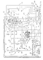
- the reference numeral 10 generally designates a motor vehicle drivetrain including an engine 12 and a (parallel shaft) transmission 14 having a reverse speed ratio and four forward speed ratios.
- Engine 12 includes a throttle mechanism 16 mechanically connected to an operator manipulated device such as an accelerator pedal (not shown) for regulating engine output torque, such torque being applied to the transmission 14 through the (engine) output shaft 18.
- the transmission 14 transmits engine output torque to a pair of drive axles 20 and 22 through a torque converter 24 and one or more of the (fluid operated) clutches 26 - 34, such clutches being applied or released according to a predetermined schedule for establishing the desired transmission speed ratio.
- an impeller or input member 36 of the torque converter 24 is connected to be rotatably driven by the output shaft 18 of engine 12 through an input shell 38.
- a turbine or output member 40 of the torque converter 24 is rotatably driven by the impeller 36 by means of fluid transfer therebetween and is connected to rotatably drive a shaft 42.
- a stator member 44 redirects the fluid which couples the impeller 36 to the turbine 40, the stator member being connected through a one-way device 46 to the housing of transmission 14.
- the torque converter 24 also includes a clutch 26 comprising a clutch plate 50 secured to the shaft 42.
- the clutch plate 50 has a friction surface 52 formed thereon adaptable to be engaged with the inner surface of the input shell 38 to form a direct mechanical drive between the (engine) output shaft 18 and the (transmission) shaft 42.
- the clutch plate 50 divides the space between input shell 38 and the turbine 40 into two fluid chambers: an apply chamber 54 and a release chamber 56.
- an apply chamber 54 exceeds that in the release chamber 56
- the friction surface 52 of clutch plate 50 is moved into engagement with the input shell 38 as shown in Figure 1, thereby engaging the clutch 26 to provide a mechanical drive connection in parallel with the torque converter 24. In such case, there is no slippage between the impeller 36 and the turbine 40.
- the circled numeral 5 represents a fluid connection to the apply chamber 54 and the circled numeral 6 represents a fluid connection to the release chamber 56.
- a (positive displacement hydraulic) pump 60 is mechanically driven by the output shaft 18 through the input shell 38 and impeller 36 as indicated by the broken line 62.
- Pump 60 receives hydraulic fluid at low pressure from a fluid reservoir 64 and supplies pressurized fluid to the transmission control elements via output line 66.
- a pressure regulator valve (PRV) 68 is connected to the output line 66 and serves to regulate the fluid pressure (hereinafter referred to as line pressure) in output line 66 by returning a controlled portion of the fluid therein to fluid reservoir 64 via the line 70.
- line pressure fluid pressure
- pressure regulator valve 68 supplies fluid pressure for the torque converter 24 via line 74. While the pump 60 and pressure regulator valve 68 designs are not critical to the present invention, a representative pump is disclosed in US Patent No. 4,342,545, and a representative pressure regulator valve is disclosed in US Patent No. 4,283,970.
- the shaft 42 and a further (transmission) shaft 90 each have a plurality of gear elements rotatably supported thereon.
- Gear elements 80 - 88 are supported on shaft 42 and gear elements 92 - 102 are supported on shaft 90.
- the gear element 88 is rigidly connected to the shaft 42, and the gear elements 98 and 102 are rigidly connected to the shaft 90.
- Gear element 92 is connected to the shaft 90 via a freewheeler or one-way device 93.
- the gear elements 80, 84, 86 and 88 are maintained in meshing engagement with the gear elements 92, 96, 98 and 100, respectively, and the gear element 82 is coupled to the gear element 94 through a reverse idler gear 103.
- the shaft 90 is coupled to the drive axles 20 and 22 through gear element 102 and a gear element 104 and a conventional differential gear set (DG) 106.
- DG differential gear set
- a dog clutch 108 is splined on the shaft 90 so as to be axially slidable thereon, and serves to rigidly connect the shaft 90 either to the gear element 96 (as shown) or the gear element 94.
- a forward speed relation between the gear element 84 and shaft 90 is established when dog clutch 108 connects the shaft 90 to gear element 96, and a reverse speed relation between the gear element 82 and shaft 90 is established when the dog clutch 108 connects the shaft 90 to the gear element 94.
- the clutches 28 - 34 each comprise an input member rigidly connected to one of the shafts 42 or 90, and an output member rigidly connected to one or more gear elements such that engagement of a clutch couples the respective gear element and shaft to effect a driving connection between the shafts 42 and 90.
- the clutch 28 couples the shaft 42 to the gear element 80; the clutch 30 couples the shaft 42 to the gear elements 82 and 84; the clutch 32 couples the shaft 90 to the gear element 100; and the clutch 34 couples the shaft 42 to the gear element 86.
- Each of the clutches 28 - 34 is biased toward a disengaged state by a return spring (not shown). Engagement of the clutch 28-34 is effected by supplying fluid pressure to an apply chamber thereof.
- the resulting torque capacity of the clutch 28-34 is a function of the applied pressure less the return spring pressure, hereinafter referred to as the working pressure.
- the circled numeral 1 represents a fluid passage for supplying pressurized fluid to the apply chamber of clutch 28; the circled numeral 2 and letter R represent a fluid passage for supplying pressurized fluid to the apply chamber of the clutch 30; the circled numeral 3 represents a fluid passage for supplying pressurized fluid to the apply chamber of the clutch 32; and the circled numeral 4 represents a fluid passage for directing pressurized fluid to the apply chamber of the clutch 34.
- the various gear elements 80 - 88 and 92 - 100 are relatively sized such that engagement of first, second, third and fourth forward speed ratios are effected by engaging the clutches 28, 30, 32 and 34, respectively, it being understood that the dog clutch 108 must be in the position depicted in Figure 1 to obtain a forward speed ratio.
- a neutral speed ratio or an effective disconnection of the drive axles 20 and 22 from the engine output shaft 18 is effected by maintaining all of the clutches 28 - 34 in a released condition.
- the speed ratios defined by the various gear element pairs are generally characterized by the ratio of the turbine speed Nt to output speed No. Representative Nt/No ratios for transmission 14 are as follows:
- Shifting from a current forward speed ratio to a desired forward speed ratio requires that the clutch associated with the current speed ratio (off-going) be disengaged and the clutch associated with the desired speed ratio (on-coming) be engaged.
- a shift from the first forward speed ratio to the second forward speed ratio involves disengagement of the clutch 28 and engagement of the clutch 30.
- the shifting between the various speed ratios is initiated in response to the achievement of predefined load conditions represented by predefined combinations of vehicle speed and engine throttle position. Data corresponding to the predefined combinations of vehicle speed and engine throttle position are stored in a look-up table or similar data structure, as described above in reference to Figure 1 c, and measured values of vehicle speed and engine throttle position are compared to the stored data to determine the desired speed ratio.
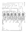
- the fluid control elements of the transmission 14 include a manual valve 140, a directional servo 160 and a plurality of (electrically operated) fluid valves 180 - 190.
- the manual valve 140 operates in response to operator demand and serves, in conjunction with directional servo 160, to direct regulated line pressure to the appropriate fluid valves 182 - 188.
- the fluid valves 182 - 188 are individually controlled to direct fluid pressure to the clutches 28 - 34.
- the fluid valve 180 is controlled to direct fluid pressure from the output line 66 to the pressure regulator valve 68, and the fluid valve 190 is controlled to direct fluid pressure from the line 74 to the clutch 26 of torque converter 24.
- the directional servo 160 operates in response to the condition of the manual valve 140 and serves to properly position the dog clutch 108.
- the manual valve 140 includes a shaft 142 for receiving axial mechanical input from the operator of the motor vehicle in relation to the speed range the operator desires.
- the shaft 142 is also connected to an indicator mechanism 144 through a suitable mechanical linkage as indicated generally by the broken line 146.
- Fluid pressure from the output line 66 is applied as an input to the manual valve 140 via input line 148 and the manual valve outputs include a forward (F) output line 150 for supplying fluid pressure for engaging forward speed ratios and a reverse (R) output line 152 for supplying fluid pressure for engaging the reverse speed ratio.
- F forward
- R reverse
- the directional servo 160 is a fluid operated device and includes an output shaft 162 connected to a shift fork 164 for axially shifting the dog clutch 108 on shaft 90 to selectively enable either forward or reverse speed ratios.
- the output shaft 162 is connected to a piston 166 axially movable within a servo housing 168.
- the axial position of the piston 166 within the servo housing 168 is determined according to the fluid pressures supplied to chambers 170 and 172.
- the forward output line 150 of manual valve 140 is connected via line 174 to the chamber 170 and the reverse output line 152 of manual valve 140 is connected via the line 176 to the chamber 172.
- the directional servo 160 also operates as a fluid valve for enabling the reverse speed ratio.
- the directional servo 160 includes an output line 178 connected to the (electrically operated) fluid valve 186.
- the passage between lines 176 and 178 is cut off; when the operator selects the reverse gear ratio, the passage between the lines 176 and 178 is open.
- the (electrically operated) fluid valves 180 - 190 each receive fluid pressure at an input passage thereof from the pump 60, and are individually controlled to direct fluid pressure to the pressure regulator valve 68 or respective clutches 26 - 34.
- the fluid valve 180 receives line pressure directly from output line 66, and is controlled to direct a variable amount of such pressure to the pressure regulator valve 68 as indicated by the circled letter V.
- the fluid valves 182, 184 and 188 receive fluid pressure from the forward output line 150 of manual valve 140, and are controlled to direct variable amounts of such pressure to the clutches 34, 32 and 28 as indicated by the circled numerals 4, 3 and 1, respectively.
- the fluid valve 186 receives fluid pressure from the forward output line 150 and the (directional servo) output line 178, and is controlled to direct a variable amount of such pressure to the clutch 30 as indicated by the circled numeral 2 and the circled letter R.
- the fluid valve 190 receives fluid pressure from line 74 of pressure regulator valve 68, and is controlled to direct a variable amount of such pressure to the release chamber 56 of the clutch 26 as indicated by the circled numeral 6.
- the apply chamber 54 of the clutch 26 is supplied with fluid pressure from the output line 74 via orifice 192 as indicated by the circled numeral 5.
- Each of the fluid valves 180 - 190 includes a spool element 210 - 220, axially movable within the respective valve body for directing fluid flow between input and output passages.
- a respective spool element 210 - 220 When a respective spool element 210 - 220 is in the rightmost position as viewed in Figure 1, the input and output passages are connected.
- Each of the fluid valves 180 - 190 includes an exhaust passage as indicated by the circled letters EX, such passage serving to drain fluid from the respective clutch when the spool element is shifted to the leftmost position as viewed in Figure 1.
- each of the fluid valves 180 - 190 includes a solenoid 222 - 232 for controlling the position of its spool element 210 - 220.
- Each such solenoid 222 - 232 comprises a plunger 234 - 244 connected to the respective spool element 210 - 220 and a solenoid coil 246 - 256 surrounding the respective plunger.
- each such solenoid coil 246 - 256 is connected to ground potential as shown, and the other terminal is connected to an output line 258 - 268 of a control unit 270 which governs the solenoid coil energization.
- the control unit 270 pulse-width- modulates the solenoid coils 246 - 256 according to a predetermined control algorithm to regulate the fluid pressure supplied to the pressure regulator valve 68 and the clutches 26 - 34, the duty cycle of such modulation being determined in relation to the desired magnitude of the supplied pressures.
- Input signals for the control unit 270 are provided on the input lines 272 - 285.
- a position sensor (S) 286 responsive to movement of the (manual valve) shaft 142 provides an input signal to the control unit 270 via line 272.
- Speed transducers 288, 290 and 292 sense the rotational velocity of various rotary members within the transmission 14 and supply speed signals in accordance therewith to the control unit 270 via lines 274, 276, and 278, respectively.
- the speed transducer 288 senses the velocity of the (transmission) shaft 42 and therefore the turbine or transmission input speed Nt;
- the speed transducer 290 senses the velocity of the drive axle 22 and therefore the transmission output speed No;
- the speed transducer 292 senses the velocity of the (engine) output shaft 18 and therefore the engine speed Ne.
- a position transducer (T) 294 is responsive to the position of the throttle mechanism 16 and provides an electrical signal in accordance therewith to control unit 270 via input line 280.
- a pressure transducer 296 senses the manifold absolute pressure (MAP) of the engine 12 and provides an electrical signal to the control unit 270 in accordance therewith via input line 282.
- a temperature sensor 298 senses the temperature of the oil in the fluid reservoir 64 and provides an electrical signal in accordance therewith to control unit 270 via input line 284.
- a shift mode selection switch 299 mounted on the vehicle instrument panel (not shown) provides an input on input line 285 indicating the driver's selection of the Normal or Performance shift modes.
- the control unit 270 responds to the input signals on input lines 272 - 285 according to a predetermined control algorithm as set forth herein, for controlling the energization of the solenoid coils 246 - 256 via output lines 258 - 268.
- the control unit 270 includes an input/output (I/O) device 300 for receiving the input signals and outputting the various pulse-width-modulation signals, and a microcomputer 302 which communicates with the I/O device 300 via an address-and-control bus 304 and a bi-directional data bus 306.
- the present invention is directed to an improved method of scheduling ratio shifting so as to avoid damage to the clutches 28-34 due to shift-related heat build-up.
- the control unit 270 only maintains cumulative energy indications for the clutches 32 and 34.
- the 3rd clutch 32 is affected by 2-3 upshifts and 3-2 downshifts; the 4th clutch 34 is affected by 3-4 upshifts and 4-3 downshifts.
- the energy due to the shift is computed according to the product of the change dNt in turbine speed, a transmission input torque variable Tv and a gain factor G2 or G3 depending on the shift mode.
- the energy due to the shift is computed according to the product of the change dNt in turbine speed, a transmission input torque variable Tv, the preshift turbine speed factor Nt(PS) and a gain factor G1.
- the preshift turbine speed factor is used to achieve a faster response in the case of high speed shifting.
- Cancelled 3-2 downshifts add a fixed amount of energy K1 to 3rd clutch 32, and cancelled 4-3 downshifts add a fixed amount of energy K1 to the 4th clutch 34.
- the accumulated energy indication is periodically reduced during nonshifting operation by an energy reduction factor (ERF) determined in relation to the sum of the turbine speed Nt and the engine throttle position (TPS).
- ERP energy reduction factor
- the cumulative energy indications for the 3rd and 4th clutches 32 and 34 are summed and compared to an energy threshold to determine the presence of excessive heating. If the summed energy indication exceeds the threshold, the control unit 270 computes an engine throttle position offset TPShys in relation to the amount by which the summed energy indication exceeds the threshold. The offset is then applied to the measured engine throttle position TPS for use in determining if upshifting is appropriate.
- the sum of the measured throttle position and the offset (TPSact + TPShys) is used to determine if upshifting is desired.
- the 2-3 upshift will not be initiated until the vehicle speed reaches 48 kph (30 mph) for the same actual throttle setting; and if the 3rd ratio is engaged, the 3-4 upshift will not be initiated until the vehicle speed reaches 88 kph (55 mph).
- the shift schedule modification Since downshifting occurs at the normal load condition, the shift schedule modification has the effect of variably increasing the hysteresis among the 2nd, 3rd and 4th speed ratios.
- the shift schedule modification never triggers a downshift since the offset does not affect the downshift determination, but once a downshift does occur, subsequent upshifting is delayed until (1) the overheating is alleviated or (2) there is a significant reduction in the engine throttle position. As a result, operation in the lower speed ratio is effectively extended to prevent further increases in the shift-related energy imparted to clutches 32 and 34.
- the successive 3-4 upshifts and 4-3 downshifts of the above example will produce a significant net increase in the heat stored in the 4th clutch 34.
- the upshifts will be determined on the basis of (TPSact + TPShys) instead of just TPSact.
- the 3-4 upshift will not occur unless the vehicle speed reaches 88 kph (55 mph), effectively extending the normal shift pattern hysteresis.
- the vehicle will remain in 3rd gear at the desired speed setting of 80 kph (50 mph) until the summed cumulative energy indications fall below the energy threshold.
- the corrective action occurs regardless of grade so as to protect the clutches 32 and 34 in the event that the throttle setting is intentionally positioned to cause repeated shifting.
- the cumulative energy indications for the 3rd and 4th clutches 32 and 34 are maintained separate and are individually compared to an energy threshold to determine the presence of excessive heating. In this way, the offsets for clutches 32 and 34 can be independently determined. If the offset for the 4th clutch 34 is greater than the offset for the 3rd clutch 32 (as would occur in the above described example), the 3rd clutch offset is used to schedule 2-3 upshifts and the 4th clutch offset is used to schedule 3-4 upshifts.
- the 3rd clutch offset is used to schedule both 2-3 upshifts and 3-4 upshifts so as to maintain the separation of the 2-3 and 3-4 upshifts.
- the second embodiment method of this invention has the effect of limiting the shift schedule modification to the 4th clutch in the event of a shift cycle which does not appreciably affect the 3rd clutch 32.
- the 4th clutch 34 is the on-coming clutch for the 3-4 upshift and the off-going clutch for the 4-3 downshift; the 3rd clutch 32 receives only slightly higher than normal heating.
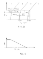
- Figure 2a This condition is graphically depicted in Figure 2a, where the offset for the 3rd clutch 32 is represented by the quantity 320; and the offset for the 4th clutch 34 is represented by the larger quantity 322.
- 2-3 upshifts at the indicated actual engine throttle setting are only extended from 40 kph (25 mph) to 43 kph (27 mph), while 3-4 upshifts are extended from 80 kph (50 mph) to 88 kph (55 mph).
- FIG. 3 depicts the energy reduction factor (ERF) which is deducted from the cumulative energy indications in nonshifting operation to reflect the dissipation of thermal energy from the clutches into the transmission fluid and housing.
- the energy indications are decremented by the value of ERF in each nonshifting loop of the flow diagram.
- the value of ERF is inversely related to the sum of the throttle position TPS and the turbine speed Nt as indicated in Figure 3.
- the maximal reduction occurs under low speed, low throttle conditions when high energy shifting is not likely to soon recur.
- minimal energy reductions occur under conditions of high speed and high throttle in order to maintain the increased hysteresis in anticipation of further high energy shifting.
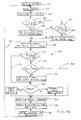
- FIGS. 4, 4a, 5, 6, 7, 8, 9 and 9a represent program instructions to be executed by the microcomputer 302 of control unit 270 in mechanizing ratio shifting and the adaptive control functions of this invention.
- the flow diagram of Figures 4/4a represent a main or executive program which calls various subroutines for executing particular control functions as necessary.
- the flow diagrams of Figures 5-9 represent the functions performed by those subroutines which are pertinent to the present invention.
- Figures 4 and 9 are specific to the first embodiment, while Figures 4a and 9a are specific to the second embodiment.
- the reference numeral 330 designates a set of program instructions executed at the initiation of each period of vehicle operation for initializing the various tables, timers, etc. used in carrying out the control functions of this invention.
- the instruction blocks 332-354 are repeatedly executed in sequence as designated by the flow diagram lines connecting such instruction blocks and the return line 356.
- Instruction block 332 reads and conditions the various input signals applied to I/O device 300 via the input lines 272-285, and updates (increments) the various control unit timers.
- Instruction block 334 calculates various terms used in the control algorithms, including the input torque Ti, the torque variable Tv and the speed ratio No/Ni.
- Instruction block 336 determines the desired speed ratio, Reds, in accordance with a number of inputs including present ratio Ract, throttle position TPS, vehicle speed Nv, manual valve position, and the clutch energy offset TPShys, if any. In transmission control, this function is generally referred to as shift pattern generation.
- the blocks designated by the reference numeral 358 include the decision block 338 for determining if a shift is in progress as indicated by the "SHIFT IN PROGRESS" flag; the decision block 340 for determining if the actual speed ratio Ract (that is, No/Nt) is equal to the desired speed ratio Rdes determined at instruction block 336; and the instruction block 342 for setting up the initial conditions for a ratio shift.
- the instruction block 342 is only executed when decision blocks 338 and 340 are both answered in the negative. In such case, instruction block 342 serves to set the old ratio variable, Rold, equal to Ract, to set the "SHIFT IN PROGRESS" flag, clear the shift timers, and to calculate the fill time tfill for the on-coming clutching device.
- the blocks designated by the reference numeral 362 include the decision block 344 for determining if the shift is an upshift or a downshift; the instruction block 346 for developing pressure commands for the on-coming and off-going clutches if the shift is an upshift; and the instruction block 348 for developing the pressure commands for the on-coming and off-going clutches if the shift is a downshift.
- the Upshift Logic is further detailed in the flow diagram of Figure 5
- the Downshift Logic is further detailed in the flow diagrams of Figures 6 and 7.
- the shift logic blocks 346 and 348 also include energy logging routines for developing the cumulative energy indications for the clutches 32 and 34.
- Instruction block 350 determines pressure commands for the PRV 68 and the nonshifting clutches, converts the commands to a PWM duty cycle based on the operating characteristics of the various actuators, and energizes the actuator coils accordingly.
- Instruction block 352 is then executed to determine the energy reduction factor ERF, and decrement the cumulative energy indications, as explained more fully in the flow diagram of Figure 8.
- the instruction block 354 is executed to calculate the clutch energy- related offset TPShys, if any, to be applied in subsequent determinations of the desired speed ratio, as explained more fully in the flow diagram of Figure 9.
- the reference numeral 360 is first executed to determine the on-coming (ONC) and off-going (OFG) pressure commands for the upshift. Representative routines for computing such pressure commands are detailed in the above-referenced patents to Downs et al. Until the shift is complete, as determined by decision block 362, the remainder of the routine is skipped, as indicated by the flow diagram line 364. Upon completion of the shift, the instruction block 366 is executed to reset the Shift In Progress flag.
- the instruction blocks 370-374 are executed to calculate the incremental energy C3 ENERGY(I) added to the 3rd clutch 32, to update the cumulative energy indication C3 ENERGY for clutch 32, and to store the cumulative indication in the term C3 ENERGY(OLD).
- the instruction blocks 378-382 are executed to calculate the incremental energy C4 ENERGY(I) added to the 4th clutch 34, to update the cumulative energy indication C4 ENERGY for clutch 34, and to store the cumulative indication in the term C4 ENERGY(OLD). If the shift is a 1-2 upshift, no energy logging is performed, as indicated by the flow diagram line 384.
- the reference numeral 390 is first executed to determine the on-coming (ONC) and off-going (OFG) pressure commands for the downshift. Representative routines for computing such pressure commands are detailed in the above-referenced patents to Downs et al. Until the shift is complete, as determined by decision block 392, the energy logging routines are skipped, and the decision block 394 is executed to determine if shift cancellation is appropriate.
- the instruction block 396 Upon completion of the shift, the instruction block 396 is executed to reset the Shift In Progress flag. If the shift is a 4-3 downshift, as determined by decision block 398, the flow diagram branch 400 is executed to log the incremental energy C4 ENERGY(I) of the 4th clutch 34. Different gain factors G2, G3 are used depending on the shift mode (i.e., Normal or Performance), as indicated by the blocks 402-406, since the energy imparted to the clutch 34 is mode-dependent. Once the incremental energy is computed, the instruction blocks 408-410 are executed to update the cumulative energy indication for clutch 34, and to store the cumulative indication in the term C4 ENERGY(OLD).
- the shift mode i.e., Normal or Performance
- the flow diagram branch 414 is executed to log the incremental energy C3 ENERGY-(I) of the 3rd clutch 32. Again, different gain factors G2, G3 are used depending on the shift mode, as indicated by the blocks 416-420. Once the incremental energy is computed, the instruction blocks 422-424 are executed to update the cumulative energy indication for clutch 32, and to store the cumulative indication in the term C3 ENERGY(OLD).
- the decision block 394 is executed to determine if shift cancellation is appropriate. This can occur, for example, if the driver of the vehicle releases the accelerator pedal in the course of a power-on downshift.
- instruction block 426 is executed to cancel the downshift and reschedule an upshift to the former ratio.
- the off-going clutch of the downshift is the same as the on-coming clutch of the upshift, and the instruction block 428 is executed to add the incremental energy to the appropriate term C3 ENERGY(OLD) or C4 ENERGY(OLD).
- the instruction block 432 is executed to increment the 3rd clutch energy indication by a fixed amount K1. If a 4-3 downshift is cancelled, as determined by decision block 434, the instruction block 436 is executed to increment the 4th clutch energy indication by the fixed amount K1.
- the instruction blocks 440-442 are executed to look up an energy reduction factor (ERF) and to decrement the 3rd and 4th clutch cumulative energy indications C3 ENERGY(OLD) and C4 ENERGY(OLD) by the amount ERF.
- ERF energy reduction factor
- the Energy Reduction Factor is determined as an inverse function of the sum of the turbine speed Nt and the engine throttle position TPS. This relationship may be stored as a look-up table or similar data structure within control unit 270.
- the instruction blocks 450-454 are executed to square and sum the cumulative energy terms C3 ENERGY(OLD) and C4 ENERGY(OLD) to form a cumulative term ENERGY, to determine the amount, if any, by which the cumulative term exceeds the energy threshold K1, and to form a throttle position offset TPShys by applying a gain term G4 to the difference.
- the block 336 will determine the desirability of a 2-3 or a 3-4 upshift based on the sum (TPS + TPShys), as described above in reference to the graphs of Figure 2.
- the second embodiment of this invention differs from the above-described first embodiment in that the cumulative energy indications for the 3rd and 4th clutches 32 and 34, and the corresponding offsets, if any, are separately maintained. This difference is highlighted by the additional blocks 460-466 in the flow diagram of Figures 4a, and by the blocks 470-476 in the flow diagram of Figure 9a. In all other respects, the flow diagrams of Figures 4a and 9a correspond to the above described flow diagrams of Figures 4 and 9, respectively.
- the decision block 460 is executed to determine if the transmission is in 2nd gear. If so, the block 336 must consider the desirability of a 2-3 upshift, and the instruction block 462 is executed to set the offset term TPShys equal to the correct value for the 3rd clutch 32. If the transmission is in 3rd gear, as determined by decision block 464, the block 336 must consider the desirability of a 3-4 upshift, and the instruction block 466 is executed to set the offset term TPShys equal to the correct value for the 4th clutch 34.
- the offset values for the 3rd and 4th clutches 32 and 34 are determined by the Offset Calculation routine referenced in block 354 of Figure 4a, and detailed in the flow diagram of Figure 9a.
- the blocks 470-472 are first executed to individually square the cumulative energy terms C3 ENERGY(OLD) and C4 ENERGY(OLD), compare them to the energy threshold K1, and multiply the difference, if any, by the gain factors K2 or K3. If the offset value TPS3hys for the 3rd clutch 32 is greater than the offset value TPS4hys for the 4th clutch 34, as determined by the decision block 474, the instruction block 476 is executed to set the TPS4hys equal to TPS3hys. Otherwise, the routine is exited and the offset values TPS3hys and TPS4hys are maintained separate, as in the example depicted in Figure 2a.
Landscapes
- Engineering & Computer Science (AREA)
- General Engineering & Computer Science (AREA)
- Mechanical Engineering (AREA)
- Physics & Mathematics (AREA)
- Fluid Mechanics (AREA)
- Control Of Transmission Device (AREA)
- Control Of Driving Devices And Active Controlling Of Vehicle (AREA)
- Control Of Vehicle Engines Or Engines For Specific Uses (AREA)
Applications Claiming Priority (2)
| Application Number | Priority Date | Filing Date | Title |
|---|---|---|---|
| US601074 | 1990-10-23 | ||
| US07/601,074 US5070746A (en) | 1990-10-23 | 1990-10-23 | Shift scheduling method for clutch energy limitation |
Publications (1)
| Publication Number | Publication Date |
|---|---|
| EP0482691A1 true EP0482691A1 (fr) | 1992-04-29 |
Family
ID=24406118
Family Applications (1)
| Application Number | Title | Priority Date | Filing Date |
|---|---|---|---|
| EP91202556A Withdrawn EP0482691A1 (fr) | 1990-10-23 | 1991-10-02 | Méthode d'opération d'une transmission |
Country Status (5)
| Country | Link |
|---|---|
| US (1) | US5070746A (fr) |
| EP (1) | EP0482691A1 (fr) |
| JP (1) | JPH0663562B2 (fr) |
| KR (1) | KR950002368B1 (fr) |
| CA (1) | CA2043950A1 (fr) |
Cited By (5)
| Publication number | Priority date | Publication date | Assignee | Title |
|---|---|---|---|---|
| EP0826909A3 (fr) * | 1996-08-30 | 1998-12-16 | Honda Giken Kogyo Kabushiki Kaisha | Dispositif d'estimation de la température de transmission de véhicule actionné hydrauliquement |
| WO1999015815A1 (fr) * | 1997-09-25 | 1999-04-01 | Zf Friedrichshafen Ag | Procede de commande d'une boite de vitesses automatique |
| FR2796341A1 (fr) * | 1999-07-14 | 2001-01-19 | Luk Lamellen & Kupplungsbau | Dispositif de commande |
| US6261204B1 (en) | 1997-10-06 | 2001-07-17 | Zf Friedrichshafen Ag | Method for adaptation of pressure of an overlapping upshifting |
| US6943676B2 (en) | 2002-10-01 | 2005-09-13 | Eaton Corporation | Clutch protection system |
Families Citing this family (18)
| Publication number | Priority date | Publication date | Assignee | Title |
|---|---|---|---|---|
| US5119695A (en) * | 1991-06-27 | 1992-06-09 | Saturn Corporation | Open-loop clutch-to-clutch upshift control having clutch overlap regulation |
| US5172609A (en) * | 1992-03-02 | 1992-12-22 | Saturn Corporation | Gradeability-based shift pattern control for an automatic transmission |
| AU663813B2 (en) * | 1993-02-24 | 1995-10-19 | Caterpillar Inc. | Drivetrain sensor and diagnostic system |
| JP2899935B2 (ja) * | 1993-08-25 | 1999-06-02 | 本田技研工業株式会社 | 車両用油圧作動式変速機の制御装置 |
| DE4333899A1 (de) * | 1993-10-05 | 1995-07-13 | Bosch Gmbh Robert | Verfahren zur Steuerung des Abtriebsmoments eines automatischen Schaltgetriebes |
| DE19602006A1 (de) * | 1995-01-28 | 1996-08-01 | Luk Getriebe Systeme Gmbh | Vorrichtung und ein Verfahren zur Ansteuerung eines Drehmomentübertragungssystems |
| KR100418662B1 (ko) * | 1996-12-20 | 2004-05-20 | 기아자동차주식회사 | 자동변속차량의엔진과열방지방법 |
| DE19712445A1 (de) * | 1997-03-25 | 1998-10-01 | Bosch Gmbh Robert | System zur Steuerung und/oder Regelung von Betriebsabläufen bei einem Kraftfahrzeug |
| DE10155462B4 (de) * | 2000-11-29 | 2020-06-04 | Schaeffler Technologies AG & Co. KG | Kraftfahrzeug |
| US6554742B2 (en) * | 2000-12-21 | 2003-04-29 | Case Corporation | Modification of shifting characteristics based upon shifting direction and drive train load |
| US7084593B2 (en) | 2002-04-10 | 2006-08-01 | Visteon Global Technologies, Inc. | Method and apparatus for thermal management of an electric power assist steering control system by compensating steering motor current |
| US7458917B2 (en) * | 2005-02-18 | 2008-12-02 | Kubota Corporation | Work vehicle with a speed change device |
| JP2010169169A (ja) * | 2009-01-21 | 2010-08-05 | Yamaha Motor Co Ltd | クラッチ制御装置およびそれを備えた自動二輪車 |
| US8618752B2 (en) | 2010-07-21 | 2013-12-31 | Superior Electron, Llc | System, architecture, and method for minimizing power consumption and increasing performance in electric vehicles |
| JP4935951B2 (ja) * | 2011-08-01 | 2012-05-23 | トヨタ自動車株式会社 | シフト制御装置 |
| US8744705B2 (en) * | 2012-03-15 | 2014-06-03 | GM Global Technology Operations LLC | System and method for determining clutch gains in a transmission during a power downshift |
| DE102014019127B4 (de) * | 2014-12-19 | 2016-11-03 | Audi Ag | Verfahren zum Betreiben einer Getriebeeinrichtung für ein Kraftfahrzeug sowie entsprechende Getriebeeinrichtung |
| US9803704B1 (en) * | 2016-08-30 | 2017-10-31 | GM Global Technology Operations LLC | System and method for controlling vehicle components during a power downshift |
Citations (4)
| Publication number | Priority date | Publication date | Assignee | Title |
|---|---|---|---|---|
| DE3702352A1 (de) * | 1986-01-30 | 1987-08-06 | Mazda Motor | Antriebssystem fuer einen vierradantrieb von fahrzeugen |
| US4838125A (en) * | 1986-02-07 | 1989-06-13 | Toyota Jidosha Kabushiki Kaisha | System for shift control in automatic transmission |
| WO1989005934A1 (fr) * | 1987-12-17 | 1989-06-29 | Kabushiki Kaisha Daikin Seisakusho | Organe de commande de changement de rapport de vitesse pour une transmission automatique |
| DE4026334A1 (de) * | 1989-08-23 | 1991-02-28 | Mazda Motor | Schaltzeitsteuereinrichtung fuer ein automatikgetriebe |
Family Cites Families (5)
| Publication number | Priority date | Publication date | Assignee | Title |
|---|---|---|---|---|
| JPS57137724A (en) * | 1981-02-19 | 1982-08-25 | Fuji Heavy Ind Ltd | Overheating prevention device of clutch |
| JPS5940048A (ja) * | 1982-08-31 | 1984-03-05 | Fuji Heavy Ind Ltd | オ−トクラツチ車の変速操作機構 |
| US4576263A (en) * | 1984-03-23 | 1986-03-18 | Eaton Corporation | Clutch control |
| JP2697828B2 (ja) * | 1987-08-28 | 1998-01-14 | 株式会社日立製作所 | 車輌用自動変速装置 |
| US4989470A (en) * | 1989-12-01 | 1991-02-05 | Ford New Holland, Inc. | Method of decelerating a power shift transmission |
-
1990
- 1990-10-23 US US07/601,074 patent/US5070746A/en not_active Expired - Lifetime
-
1991
- 1991-06-05 CA CA002043950A patent/CA2043950A1/fr not_active Abandoned
- 1991-10-02 EP EP91202556A patent/EP0482691A1/fr not_active Withdrawn
- 1991-10-21 KR KR1019910018539A patent/KR950002368B1/ko active IP Right Grant
- 1991-10-23 JP JP3275481A patent/JPH0663562B2/ja not_active Expired - Lifetime
Patent Citations (4)
| Publication number | Priority date | Publication date | Assignee | Title |
|---|---|---|---|---|
| DE3702352A1 (de) * | 1986-01-30 | 1987-08-06 | Mazda Motor | Antriebssystem fuer einen vierradantrieb von fahrzeugen |
| US4838125A (en) * | 1986-02-07 | 1989-06-13 | Toyota Jidosha Kabushiki Kaisha | System for shift control in automatic transmission |
| WO1989005934A1 (fr) * | 1987-12-17 | 1989-06-29 | Kabushiki Kaisha Daikin Seisakusho | Organe de commande de changement de rapport de vitesse pour une transmission automatique |
| DE4026334A1 (de) * | 1989-08-23 | 1991-02-28 | Mazda Motor | Schaltzeitsteuereinrichtung fuer ein automatikgetriebe |
Non-Patent Citations (3)
| Title |
|---|
| & JP-A-2 217 660 (MAZDA) 30 August 1990 * |
| PATENT ABSTRACTS OF JAPAN vol. 14, no. 519 (M-1048)14 November 1990 * |
| PATENT ABSTRACTS OF JAPAN vol. 9, no. 98 (M-375)(1821) 27 April 1985 & JP-A-59 222 655 ( MAZDA ) 14 December 1984 * |
Cited By (9)
| Publication number | Priority date | Publication date | Assignee | Title |
|---|---|---|---|---|
| EP0826909A3 (fr) * | 1996-08-30 | 1998-12-16 | Honda Giken Kogyo Kabushiki Kaisha | Dispositif d'estimation de la température de transmission de véhicule actionné hydrauliquement |
| US5960669A (en) * | 1996-08-30 | 1999-10-05 | Honda Giken Kogyo Kabushiki Kaisha | System for estimating temperature of vehicle hydraulically-operated transmission |
| WO1999015815A1 (fr) * | 1997-09-25 | 1999-04-01 | Zf Friedrichshafen Ag | Procede de commande d'une boite de vitesses automatique |
| US6285940B1 (en) * | 1997-09-25 | 2001-09-04 | Zf Friedrichshafen Ag | Method for controlling an automatic gearbox |
| US6261204B1 (en) | 1997-10-06 | 2001-07-17 | Zf Friedrichshafen Ag | Method for adaptation of pressure of an overlapping upshifting |
| FR2796341A1 (fr) * | 1999-07-14 | 2001-01-19 | Luk Lamellen & Kupplungsbau | Dispositif de commande |
| WO2001006152A1 (fr) * | 1999-07-14 | 2001-01-25 | Luk Lamellen Und Kupplungsbau Gmbh | Dispositif pour commander en fonction de la temperature un embrayage ou une boite de vitesses de vehicule automobile |
| DE10082053B4 (de) * | 1999-07-14 | 2019-06-06 | Schaeffler Technologies AG & Co. KG | Steuerungsvorrichtung einer Kupplung oder eines Fahrzeuggetriebes |
| US6943676B2 (en) | 2002-10-01 | 2005-09-13 | Eaton Corporation | Clutch protection system |
Also Published As
| Publication number | Publication date |
|---|---|
| KR950002368B1 (ko) | 1995-03-17 |
| KR920007854A (ko) | 1992-05-27 |
| JPH04262167A (ja) | 1992-09-17 |
| JPH0663562B2 (ja) | 1994-08-22 |
| US5070746A (en) | 1991-12-10 |
| CA2043950A1 (fr) | 1992-04-24 |
Similar Documents
| Publication | Publication Date | Title |
|---|---|---|
| US5070746A (en) | Shift scheduling method for clutch energy limitation | |
| US5172609A (en) | Gradeability-based shift pattern control for an automatic transmission | |
| EP0310275B1 (fr) | Modification du schéma de commutation en cas de défaillance pour une transmission, commandée électroniquement | |
| US4653351A (en) | Clutch-to-clutch power-on downshifting in a motor vehicle automatic transmission | |
| US5036729A (en) | Coast-sync-coast downshift control method for clutch-to-clutch transmission shifting | |
| EP0816720B1 (fr) | Contrôle de changement de vitesse stabilisé pour transmission automatique | |
| US5152192A (en) | Dynamic shift control for an automatic transmission | |
| US5129286A (en) | Engine torque management for engine speed flare suppression for clutch-to-clutch-upshifting | |
| EP0231994B1 (fr) | Dispositif de commande pour le changement à une vitesse inférieure d'une boîte de vitesses de véhicule automobile en frein-moteur entre deux rappôts d'engrenage à changement par des embrayages | |
| US5151858A (en) | Multiple mode adaptive pressure control for an automatic transmission | |
| US5038636A (en) | Double transition downshift control for an automatic transmission | |
| EP0520532A2 (fr) | Méthode de commande à boucle ouverte pour transmission automatique | |
| EP0525853B1 (fr) | Procédé de commande d'une transmission automatique | |
| EP0800124B1 (fr) | Système de régulation adaptif de changements de vitesse utilisant la logique floue | |
| US5251512A (en) | Dynamic shift control for an automatic transmission | |
| AU630833B2 (en) | Double transition upshift control method for an automatic transmission | |
| US5289741A (en) | Adaptive transmission pressure control with run-through detection | |
| EP0512596B1 (fr) | Méthode de commande du programme de changement de vitesse pour la boîte automatique d'un véhicule motorisé | |
| EP0668456A2 (fr) | Méthode et dispositif pour commander un changement de vitesse dans une transmission automatique |
Legal Events
| Date | Code | Title | Description |
|---|---|---|---|
| PUAI | Public reference made under article 153(3) epc to a published international application that has entered the european phase |
Free format text: ORIGINAL CODE: 0009012 |
|
| AK | Designated contracting states |
Kind code of ref document: A1 Designated state(s): DE FR GB |
|
| 17P | Request for examination filed |
Effective date: 19920521 |
|
| 17Q | First examination report despatched |
Effective date: 19940131 |
|
| STAA | Information on the status of an ep patent application or granted ep patent |
Free format text: STATUS: THE APPLICATION IS DEEMED TO BE WITHDRAWN |
|
| 18D | Application deemed to be withdrawn |
Effective date: 19950503 |