EP0482361B1 - Method for the parallel regulation of step transformers - Google Patents
Method for the parallel regulation of step transformers Download PDFInfo
- Publication number
- EP0482361B1 EP0482361B1 EP91116091A EP91116091A EP0482361B1 EP 0482361 B1 EP0482361 B1 EP 0482361B1 EP 91116091 A EP91116091 A EP 91116091A EP 91116091 A EP91116091 A EP 91116091A EP 0482361 B1 EP0482361 B1 EP 0482361B1
- Authority
- EP
- European Patent Office
- Prior art keywords
- voltage
- parallel
- current
- transformers
- interference magnitude
- Prior art date
- Legal status (The legal status is an assumption and is not a legal conclusion. Google has not performed a legal analysis and makes no representation as to the accuracy of the status listed.)
- Expired - Lifetime
Links
Images
Classifications
-
- G—PHYSICS
- G05—CONTROLLING; REGULATING
- G05F—SYSTEMS FOR REGULATING ELECTRIC OR MAGNETIC VARIABLES
- G05F1/00—Automatic systems in which deviations of an electric quantity from one or more predetermined values are detected at the output of the system and fed back to a device within the system to restore the detected quantity to its predetermined value or values, i.e. retroactive systems
- G05F1/10—Regulating voltage or current
- G05F1/12—Regulating voltage or current wherein the variable actually regulated by the final control device is ac
- G05F1/24—Regulating voltage or current wherein the variable actually regulated by the final control device is ac using bucking or boosting transformers as final control devices
Abstract
Description
Die Erfindung betrifft ein Verfahren zur Parallellaufregelung von mit Stufenschaltern ausgestatteten Stufentransformatoren gemäß dem Oberbegriff des Patentanspruches.The invention relates to a method for parallel operation control of step transformers equipped with tap changers according to the preamble of the claim.
Verfahren zur Regelung des Parallellaufs von Stufentransformatoren sind bereits in zahlreichen Formen bekannt.Methods for regulating the parallel operation of step transformers are already known in numerous forms.
Sind die parallelzuschaltenden Stufentransformatoren hinsichtlich ihrer Spannungsstufen und Stufenzahlen identisch, gestaltet sich das Regelverfahren relativ einfach; hierbei kommt es lediglich darauf an, daß sich alle Stufenschalter jederzeit auf der gleichen Spannungsstufe befinden, da sonst ein Ausgleichsstrom zwischen den Sekundärwicklungen entsteht. Dies ist bereits aus DE 11 39 918 bekannt. Aus AT 126 517 ist es dazu weiterhin bekannt, Hilfsumschalter vorzusehen, die die gleiche Kontaktzahl wie die Stufenschalter aufweisen.If the step transformers to be connected in parallel are identical with regard to their voltage steps and number of steps, the control process is relatively simple; all that is important is that all tap changers are at the same voltage level at all times, otherwise there will be a compensating current between the secondary windings. This is already known from DE 11 39 918. From AT 126 517 it is also known to provide auxiliary changeover switches that have the same number of contacts as the tap changer.
Kompliziertere Regelverfahren ergeben sich hingegen, wenn es sich bei den zu steuernden parallellaufenden Stufentransformatoren um solche mit unterschiedlichen Spannungsstufungen und Stufenzahlen handelt; in diesen Fällen bedarf es einer Regelung im engeren Sinne.On the other hand, there are more complicated control procedures if the parallel step transformers to be controlled are those with different voltage steps and number of steps; in these cases a regulation in the narrower sense is required.
Die dazu bekannten Regelverfahren lassen sich im wesentlichen in zwei Gruppen einteilen:The known control methods can essentially be divided into two groups:
Zum einen sind, beispielsweise aus DE 11 56 880, die sog. "Master-Slave"-Verfahren bekannt, d.h. es wird eine Gleichlaufsteuerung realisiert, bei der ein Stufentransformator als "Master" angewählt wird, dem die anderen Stufentransformatoren "nachlaufen".On the one hand, for example from DE 11 56 880, the so-called "master-slave" methods are known, ie a synchronous control is implemented in which a step transformer is used as "Master" is selected, which the other step transformers "follow".
Die zweite Möglichkeit ist eine echte Parallellaufregelung, wobei alle Stufentransformatoren im gleichberechtigten Betrieb arbeiten.The second option is real parallel control, with all step transformers working in equal operation.
Aus der SIEMENS-Zeitschrift 1956, Heft 2, Seiten 100 ff.: "Die Parallelsteuerung von Transformatoren mit Stufenschalter" ist eine entsprechende Regeleinrichtung bekannt, bei der jedem Stufenschalter ein Steuergerät zugeordnet ist; eine ähnliche Einrichtung wird in DE 30 32 874 offenbart.A corresponding control device is known from the SIEMENS magazine 1956,
Schließlich ist aus der Betriebsanweisung 63/82 (BA 63/62 de/en-1088/1000), Stand Oktober 1988, der Maschinenfabrik Reinhausen GmbH eine Einrichtung zur automatischen Parallellaufregelung nach der Ausgleichstrommethode bekannt geworden, die vorsieht, daß jeder Stufentransformator mit einem eigenen Spannungsregler und einem zugehörigen Parallelsteuergerät ausgestattet ist.Finally, from the operating instructions 63/82 (BA 63/62 de / en-1088/1000), as of October 1988, the Maschinenfabrik Reinhausen GmbH has become aware of a device for automatic parallel control according to the balancing current method, which provides that each step transformer has its own Voltage regulator and an associated parallel control unit is equipped.
Bei dem dieser Einrichtung zugrundeliegenden Verfahren messen die Spannungsregler die jeweilige Spannung mittels eines Spannungswandlers; die nachgeordneten Parallelsteuergeräte sind erforderlich, um zu gewährleisten, daß eine unterschiedliche Stufenstellung der parallelgeschalteten Stufentransformatoren auch dann zur Regelung führt, wenn die Summe der Spannungen der Sollspannung des Systems entspricht.In the method on which this device is based, the voltage regulators measure the respective voltage by means of a voltage converter; the downstream parallel control units are required to ensure that a different step position of the step transformers connected in parallel leads to regulation even if the sum of the voltages corresponds to the nominal voltage of the system.
Die Parallelsteuergeräte generieren bei diesem Verfahren eine Steuergröße, die proportional dem Kreisblindstromanteil des eigenen Stufentransformators ist und auf die Spannungsregler wirkt.With this method, the parallel control units generate a control variable that is proportional to the circulating reactive current component of their own step transformer and acts on the voltage regulator.
Diese Schaltung und das zugrundeliegende Verfahren sind für die Regelung auf einer Sammelschiene praktikabel. Wenn jedoch eine beliebige Verknüpfung mit Stufentransformatoren, die auf einer zweiten Sammelschiene arbeiten, möglich sein soll, wird die entsprechende Schaltung zur Durchführung des Verfahrens sehr kompliziert und birgt zahlreiche Fehlermöglichkeiten in sich.This circuit and the underlying method are practicable for control on a busbar. However, if any connection to step transformers that work on a second busbar is to be possible, the corresponding circuit for carrying out the method becomes very much complicated and contains numerous possibilities for errors.
Dies dadurch, daß sich zahlreiche Querverbindungen zwischen den Parallelsteuergeräten und für die Erfassung der Systemkonfiguration erforderlichen zugeordneten Hilfs- bzw. Signalkontakten ergeben. Dieser Aufwand steigt entsprechend der bei zunehmender Zahl vorhandener Stufentransformatoren rasch zunehmenden Variantenzahl möglicher Schaltungsanordnungen dieser Stufentransformatoren ebenfalls sehr stark und macht universelle und erweiterungsfähige Schaltungen praktisch unmöglich.This is due to the fact that there are numerous cross-connections between the parallel control devices and associated auxiliary or signal contacts required for the detection of the system configuration. This expenditure increases correspondingly to the rapidly increasing number of possible circuit arrangements of these step transformers with an increasing number of existing step transformers and makes universal and expandable circuits practically impossible.
Aufgabe der Erfindung ist es, durch ein neuartiges Verfahren zur Parallellaufregelung ohne Querverbindungen zwischen den jedem Stufentransformator zugeordneten Steuer- und Regeleinrichtungen auszukommen und damit die Möglichkeit zu schaffen, eine universelle Beschaltung des Systems bei jeder beliebigen Stufentransformatoren- und Sammelschienenzahl zu ermöglichen, die auch nachträglich mit geringem Aufwand erweiterungsfähig ist. Zudem soll der Schaltungsaufwand dadurch weiter gesenkt werden, daß es das neuartige Verfahren gestatten soll, nur mit einem Parallelsteuergerät auszukommen.The object of the invention is to use a new method for parallel control without cross connections between the control and regulating devices assigned to each step transformer and thus to create the possibility of enabling a universal connection of the system to any number of step transformers and busbars, which can also be added subsequently is expandable with little effort. In addition, the circuit complexity is to be further reduced by the fact that the novel method should allow only one parallel control unit to be used.
Diese Aufgabe wird erfindungsgemäß durch das Verfahren gemäß dem Patentanspruch gelöst.This object is achieved by the method according to the patent claim.
Das neue Verfahren erfordert bei der schaltungstechnischen Realisierung ein, vorzugsweise mikroprozessorgesteuertes, Parallelsteuergerät, das seriell mit den einzelnen Spannungsreglern, die, wie nach dem Stand der Technik bekannt, weiterhin jeweils jedem Stufentransformator zugeordnet sind, in Verbindung steht. Durch die seriellen Datenleitungen ergibt sich eine geringere Wahrscheinlichkeit von Verdrahtungs- und anderen Fehlern.When implementing the circuitry, the new method requires a, preferably microprocessor-controlled, parallel control device which is connected in series to the individual voltage regulators, which, as is known from the prior art, are each associated with each step transformer. The serial data lines reduce the likelihood of wiring and other errors.
Die bisher notwendige Verbindung zum Motorantrieb zur Stufenstellungserfassung entfällt ebenfalls.The previously necessary connection to the motor drive for step position detection is also eliminated.
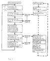
Das erfindungsgemäße Verfahren soll nachstehend an einem Ausführungsbeispiel näher erläutert werden:
- Fig. 1
- zeigt eine schematische Darstellung der ablaufenden Verfahrensschritte
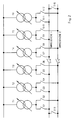
- Fig. 2
- zeigt ein Prinzipschaltbild von beispielsweise 6 Stufentransformatoren in einem Zweisammelschienensystem
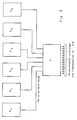
- Fig. 3
- zeigt die prinzipielle serielle Zusammenschaltung der 6 Stufentransformatoren mit einem einzigen Parallelsteuergerät zur Durchführung des Verfahrens.
- Fig. 1
- shows a schematic representation of the process steps taking place
- Fig. 2
- shows a basic circuit diagram of, for example, 6 step transformers in a double busbar system
- Fig. 3
- shows the basic serial interconnection of the 6 step transformers with a single parallel control device for performing the method.
Mittels der Meldekontakte S1...S16 der entsprechenden Trenner und Leistungsschalter wird einem Parallelsteuergerät P die aktuelle Stufentransformatorenkonfiguration, d.h. die Information, welche Stufentransformatoren auf welchen Sammelschienen parallelgeschaltet arbeiten, mitgeteilt.By means of the signaling contacts S1 ... S16 of the corresponding isolators and circuit breakers, a parallel control unit P is informed of the current step transformer configuration, i.e. the information about which step transformers work on which busbars connected in parallel.
Es ist ersichtlich, daß die Stufentransformatoren T1...T6 dabei in allen denkbaren Schaltkombinationen mit den beiden Sammelschienen verknüpft sein können.It can be seen that the step transformers T1 ... T6 can be linked to the two busbars in all conceivable switching combinations.
Jedem Stufentransformator T1...T6 ist ein Spannungsregler R1...R6 zugeordnet, der die Amplituden von Spannung und Strom und den Phasenwinkel an jedem Stufentransformator auf an sich bekannte Weise mißt und nacheinander diese Werte über serielle Datenleitungen an ein Parallelsteuergerät P übermittelt.Each step transformer T1 ... T6 is assigned a voltage regulator R1 ... R6, which measures the amplitudes of voltage and current and the phase angle on each step transformer in a manner known per se and successively transmits these values to a parallel control device P via serial data lines.
Anschließend werden daraus für jeden Spannungsregler R1...R6 getrennt Teillaststrom und Kreisblindstrom ermittelt und daraus die Störgröße für jeden Spannungsregler R1...R6 berechnet.Subsequently, partial load current and circulating reactive current are determined separately for each voltage regulator R1 ... R6 and the disturbance variable for each voltage regulator R1 ... R6 is calculated.
Nachfolgend werden die Störgröße und der Teillaststrom über die seriellen Datenleitungen wiederum den einzelnen Spannungsreglern R1...R6 übermittelt.Subsequently, the disturbance variable and the partial load current are in turn transmitted to the individual voltage regulators R1 ... R6 via the serial data lines.
Danach wird in jedem Spannungsregler R1...R6 eine Störgröße auf an sich bekannte Weise nach der Methode der Line-drop-compensation (LDC) zum Kompensieren des Spannungsabfalls (vgl. DE-A-2 504 278) erzeugt.Then, in each voltage regulator R1 ... R6, a disturbance variable is generated in a manner known per se according to the line drop compensation (LDC) method for compensating for the voltage drop (cf. DE-A-2 504 278).
Damit ist auf an sich bekannte Weise der Leitungsspannungsabfall kompensierbar.The line voltage drop can thus be compensated for in a manner known per se.
Dies kann durch eine Schaltungsanordnung, beispielsweise nach DE 26 16 798 oder DE 26 30 933, oder auch durch einen geeigneten Programmteil geschehen.This can be done by a circuit arrangement, for example according to DE 26 16 798 or DE 26 30 933, or by a suitable program part.
Schließlich werden für jeden Spannungsregler R1...R6 die Meßspannung, die aus dem Parallelsteuergerät übermittelte Störgröße und die Störgröße aus der Kompensation des Leitungsspannungsabfalls addiert und das Ergebnis wird als neuer Wert auf den entsprechenden Spannungsregler geschaltet.Finally, for each voltage regulator R1 ... R6, the measurement voltage, the disturbance variable transmitted from the parallel control device and the disturbance variable from the compensation of the line voltage drop are added and the result is switched to the corresponding voltage regulator as a new value.
In weiterer Ausgestaltung der Erfindung kann die serielle Datenleitung anstatt, wie beschrieben, als Punkt-zu-Punkt-Verbindung auch als Ringleitung (z.B. RS485) ausgeführt sein.In a further embodiment of the invention, the serial data line can also be designed as a ring line (e.g. RS485) instead of as a point-to-point connection as described.
Claims (2)
- Method for the regulation of parallel operation of tapped transformers (T1...T6) operating in parallel in any switching combination in a double bus bar system and equipped with tap switches for switching different voltage taps under load, wherein the respective setting of the isolating and power switches of the system is detected by signalling contacts (S1...S16) and wherein moreover each tapped transformer (T1...T6) is associated with a separate voltage regulator (R1...R6), which acts on the respective motor drive which in turn actuates the associated tap switch, characterised thereby that in a parallel control apparatus (P) it is detected through the setting of the signalling contacts (S1...S16) which tapped transformers (T1...T6) operate in which configuration in the parallel operation that subsequently in the voltage regulators (R1...R6) the actual values of the amplitude and the phase angle of voltage and current of the respective tapped transformer (T1...T6) are measured and communicated to the parallel control apparatus (P) by way of serial data lines, that following thereon the partial load current and the circuit reactive current are determined for each tapped transformer (T1...T6) from those individual values and thereafter a first interference magnitude is generated as an influencing magnitude for the individual voltage regulators (R1...R6), that the values of the partial load current and the first interference magnitude are transmitted respectively by way of the serial data lines from the parallel control apparatus (P) to the corresponding voltage regulators (R1...R6), that subsequently a second interference magnitude for compensation for the line voltage drop is generated in the corresponding voltage regulator from the respective partial load current and that finally the values of measured voltage, first interference magnitude and second interference magnitude are summated in each voltage regulator (R1...R6) and the regulating magnitudes are imposed.
- Method according to claim 1, characterised thereby that the serial data line is constructed as a ring main.
Applications Claiming Priority (2)
| Application Number | Priority Date | Filing Date | Title |
|---|---|---|---|
| DE4033391 | 1990-10-20 | ||
| DE4033391A DE4033391C2 (en) | 1990-10-20 | 1990-10-20 | Procedure for parallel control of step transformers |
Publications (3)
| Publication Number | Publication Date |
|---|---|
| EP0482361A2 EP0482361A2 (en) | 1992-04-29 |
| EP0482361A3 EP0482361A3 (en) | 1992-12-09 |
| EP0482361B1 true EP0482361B1 (en) | 1995-08-09 |
Family
ID=6416709
Family Applications (1)
| Application Number | Title | Priority Date | Filing Date |
|---|---|---|---|
| EP91116091A Expired - Lifetime EP0482361B1 (en) | 1990-10-20 | 1991-09-21 | Method for the parallel regulation of step transformers |
Country Status (4)
| Country | Link |
|---|---|
| US (1) | US5210443A (en) |
| EP (1) | EP0482361B1 (en) |
| AT (1) | ATE126370T1 (en) |
| DE (2) | DE4033391C2 (en) |
Families Citing this family (17)
| Publication number | Priority date | Publication date | Assignee | Title |
|---|---|---|---|---|
| WO1993004515A1 (en) * | 1991-08-23 | 1993-03-04 | Mitsubishi Denki Kabushiki Kaisha | Distribution apparatus |
| DE4424886C1 (en) * | 1994-07-14 | 1995-11-16 | Reinhausen Maschf Scheubeck | Layout configuration representation system using monitor field |
| US5530338A (en) * | 1995-03-06 | 1996-06-25 | Beckwith; Robert W. | Load tapchanger transformer paralleling by daisy chain comparison of load currents |
| US6788035B2 (en) * | 2001-06-12 | 2004-09-07 | Primarion, Inc. | Serial bus control method and apparatus for a microelectronic power regulation system |
| US7271572B2 (en) | 2005-10-24 | 2007-09-18 | Schweitzer Engineering Laboratories, Inc. | Apparatus and methods for providing a voltage adjustment for single-phase voltage regulator operation in a three-phase power system |
| US7504806B2 (en) * | 2005-10-21 | 2009-03-17 | Schweitzer Engineering Laboratories, Inc. | Apparatus and methods for controlling operation of a single-phase voltage regulator in a three-phase power system |
| DE102008053193A1 (en) * | 2008-10-24 | 2010-04-29 | Maschinenfabrik Reinhausen Gmbh | Method for parallel control of transformers with tap changers |
| US7888815B2 (en) * | 2008-12-31 | 2011-02-15 | Lsi Corporation | AC/DC power supply, a method of delivering DC power at multiple voltages and a computer data storage system employing the power supply or the method |
| US9256232B2 (en) | 2009-06-12 | 2016-02-09 | Schweitzer Engineering Laboratories, Inc. | Voltage regulation using multiple voltage regulator controllers |
| US8427131B2 (en) * | 2009-06-12 | 2013-04-23 | Schweitzer Engineering Laboratories Inc | Voltage regulation at a remote location using measurements from a remote metering device |
| US8476874B2 (en) * | 2009-10-13 | 2013-07-02 | Schweitzer Engineering Laboratories, Inc | Systems and methods for synchronized control of electrical power system voltage profiles |
| BRPI1106471B1 (en) | 2011-10-17 | 2020-12-22 | Companhia Hidro Elétrica Do São Francisco - Chesf | voltage regulation method and parallelism between different models of voltage sources and / or energized high voltage spans |
| US8847570B1 (en) * | 2013-04-30 | 2014-09-30 | Utilidata, Inc. | Line drop compensation methods and systems |
| DE102014119158A1 (en) | 2014-12-19 | 2016-06-23 | Maschinenfabrik Reinhausen Gmbh | Selective parallel running procedure for measuring / control devices |
| US11361920B2 (en) | 2017-01-06 | 2022-06-14 | Eaton Intelligent Power Limited | Control system for an electrical apparatus |
| EP3447602A1 (en) * | 2017-08-22 | 2019-02-27 | Siemens Aktiengesellschaft | Method and device for controlling the voltage of a transformer system |
| CN109921380B (en) * | 2019-02-02 | 2021-05-07 | 国网浙江省电力有限公司丽水供电公司 | Protection device for preventing re-moving parallel device from reverse charging |
Citations (1)
| Publication number | Priority date | Publication date | Assignee | Title |
|---|---|---|---|---|
| DE2504278B1 (en) * | 1975-02-01 | 1976-04-15 | Gossen Gmbh | Voltage regulator with electronic circuit - is for compensation of voltage drop on transmission lines of three phase or AC networks |
Family Cites Families (9)
| Publication number | Priority date | Publication date | Assignee | Title |
|---|---|---|---|---|
| AT126517B (en) * | 1929-06-11 | 1932-01-25 | Siemens Ag | Device for monitoring the operation of a group of step transformers working in parallel. |
| DE1156880B (en) * | 1957-11-04 | 1963-11-07 | Licentia Gmbh | Device for controlling a medium level equality for regulating transformers |
| FR1279465A (en) * | 1960-11-10 | 1961-12-22 | Acec | Protection device for transformers operating in parallel |
| DE2616798B1 (en) * | 1976-04-15 | 1977-10-06 | Reinhausen Maschf Scheubeck | VOLTAGE REGULATOR FOR STEPPED TRANSFORMERS |
| DE2630933C3 (en) * | 1976-07-09 | 1980-07-31 | Maschinenfabrik Reinhausen Gebrueder Scheubeck Gmbh & Co Kg, 8400 Regensburg | Voltage regulator for step transformers |
| US4403292A (en) * | 1979-05-30 | 1983-09-06 | Sundstrand Corporation | Control for an electrical generating and distribution system, and method of operation |
| JPS5913730B2 (en) * | 1979-09-05 | 1984-03-31 | 富士写真フイルム株式会社 | Color image forming method |
| DE3032874C2 (en) * | 1980-09-01 | 1984-05-03 | Volta-Werke Elektricitäts-Gesellschaft mbH, 1000 Berlin | Device for controlling the automatic parallel operation of a large number of transformers |
| DE4004671C1 (en) * | 1990-02-15 | 1991-09-19 | Maschinenfabrik Reinhausen Gmbh, 8400 Regensburg, De | Automatically identifying installation configuration - using computer to cover stepped transformers coupled to bus=bars as desired and for regulation |
-
1990
- 1990-10-20 DE DE4033391A patent/DE4033391C2/en not_active Expired - Fee Related
-
1991
- 1991-09-21 DE DE59106210T patent/DE59106210D1/en not_active Expired - Fee Related
- 1991-09-21 AT AT91116091T patent/ATE126370T1/en not_active IP Right Cessation
- 1991-09-21 EP EP91116091A patent/EP0482361B1/en not_active Expired - Lifetime
- 1991-10-15 US US07/776,571 patent/US5210443A/en not_active Expired - Fee Related
Patent Citations (1)
| Publication number | Priority date | Publication date | Assignee | Title |
|---|---|---|---|---|
| DE2504278B1 (en) * | 1975-02-01 | 1976-04-15 | Gossen Gmbh | Voltage regulator with electronic circuit - is for compensation of voltage drop on transmission lines of three phase or AC networks |
Non-Patent Citations (1)
| Title |
|---|
| Betriebsanweisung 63/82 Maschinenfabrik Reinhausen * |
Also Published As
| Publication number | Publication date |
|---|---|
| DE59106210D1 (en) | 1995-09-14 |
| ATE126370T1 (en) | 1995-08-15 |
| EP0482361A2 (en) | 1992-04-29 |
| DE4033391A1 (en) | 1992-04-23 |
| US5210443A (en) | 1993-05-11 |
| DE4033391C2 (en) | 1994-06-09 |
| EP0482361A3 (en) | 1992-12-09 |
Similar Documents
| Publication | Publication Date | Title |
|---|---|---|
| EP0482361B1 (en) | Method for the parallel regulation of step transformers | |
| EP1168271A2 (en) | Field bus coupling system for actuators or sensors | |
| WO2016001149A1 (en) | Method and device for testing a tap changer of a transformer | |
| EP3164726A1 (en) | Method and device for testing a tap changer of a transformer | |
| DE4004671C1 (en) | Automatically identifying installation configuration - using computer to cover stepped transformers coupled to bus=bars as desired and for regulation | |
| EP0083306A1 (en) | Process and device to control at least one compensation coil in a polyphase network | |
| EP2389723B1 (en) | Method for parallel control of transformers with tap changers | |
| EP0024564A1 (en) | Method of computer-backed function testing of the input and output elements of a controller, and testing apparatus for carrying out the method | |
| AT516004B1 (en) | Method and device for testing a tap changer of a transformer | |
| DE19850869A1 (en) | Line coupling and use of a line coupling in a bus system | |
| EP4100751B1 (en) | Switchable amplifier | |
| EP0692858B1 (en) | Method for displaying a power plant configuration of any of more power busbars parallel connected step transformators with a tension regulator and a display array for the display | |
| DE2721813C3 (en) | Method for determining the insulation resistance of electrical networks with converters and a device for carrying out the method | |
| AT412248B (en) | METHOD FOR DETECTING ASYMMETRIES IN ROTARY FIELD MACHINES DURING OPERATION BY RECONSTRUCTION OF THE CURRENT INDICATOR | |
| DE2904470A1 (en) | On-load transformer setter - includes two control and one excitation winding on each phase limb | |
| DE4301810A1 (en) | Single-phase thyristor control circuit for aluminium@ wire resistance evaporator via transformer | |
| DE102020216365A1 (en) | Control circuit for a group of electrical machines and a method for operating a motor system with multiple electric motors | |
| DE731011C (en) | Feedback device for high-voltage remote control systems | |
| EP0446451A2 (en) | Method of operating a reactive power regulator | |
| EP0540765B1 (en) | Circuit generating a clock signal synchronised with the mains | |
| DE969345C (en) | Method and device for error adjustment of electrical power and work meters, in particular electricity meters | |
| DE577864C (en) | Circuit arrangement for the automatic elimination or reduction of afterimage errors | |
| Grondin | Computer-dedicated voltage regulation method for distribution substations | |
| EP0232809A1 (en) | Method and device for the parallel switching of branches or networks containing synchronous generators | |
| DE102018204413A1 (en) | Control of saturation effects of transformers |
Legal Events
| Date | Code | Title | Description |
|---|---|---|---|
| PUAI | Public reference made under article 153(3) epc to a published international application that has entered the european phase |
Free format text: ORIGINAL CODE: 0009012 |
|
| AK | Designated contracting states |
Kind code of ref document: A2 Designated state(s): AT BE CH DE FR LI NL |
|
| EL | Fr: translation of claims filed | ||
| PUAL | Search report despatched |
Free format text: ORIGINAL CODE: 0009013 |
|
| AK | Designated contracting states |
Kind code of ref document: A3 Designated state(s): AT BE CH DE FR LI NL |
|
| 17P | Request for examination filed |
Effective date: 19921117 |
|
| 17Q | First examination report despatched |
Effective date: 19940704 |
|
| GRAA | (expected) grant |
Free format text: ORIGINAL CODE: 0009210 |
|
| AK | Designated contracting states |
Kind code of ref document: B1 Designated state(s): AT BE CH DE FR LI NL |
|
| REF | Corresponds to: |
Ref document number: 126370 Country of ref document: AT Date of ref document: 19950815 Kind code of ref document: T |
|
| ET | Fr: translation filed | ||
| REF | Corresponds to: |
Ref document number: 59106210 Country of ref document: DE Date of ref document: 19950914 |
|
| PLBE | No opposition filed within time limit |
Free format text: ORIGINAL CODE: 0009261 |
|
| STAA | Information on the status of an ep patent application or granted ep patent |
Free format text: STATUS: NO OPPOSITION FILED WITHIN TIME LIMIT |
|
| 26N | No opposition filed | ||
| PGFP | Annual fee paid to national office [announced via postgrant information from national office to epo] |
Ref country code: CH Payment date: 20000831 Year of fee payment: 10 |
|
| PGFP | Annual fee paid to national office [announced via postgrant information from national office to epo] |
Ref country code: BE Payment date: 20000907 Year of fee payment: 10 |
|
| PGFP | Annual fee paid to national office [announced via postgrant information from national office to epo] |
Ref country code: AT Payment date: 20000925 Year of fee payment: 10 |
|
| PGFP | Annual fee paid to national office [announced via postgrant information from national office to epo] |
Ref country code: FR Payment date: 20000929 Year of fee payment: 10 |
|
| PGFP | Annual fee paid to national office [announced via postgrant information from national office to epo] |
Ref country code: NL Payment date: 20000930 Year of fee payment: 10 |
|
| PGFP | Annual fee paid to national office [announced via postgrant information from national office to epo] |
Ref country code: DE Payment date: 20001101 Year of fee payment: 10 |
|
| PG25 | Lapsed in a contracting state [announced via postgrant information from national office to epo] |
Ref country code: AT Free format text: LAPSE BECAUSE OF NON-PAYMENT OF DUE FEES Effective date: 20010921 |
|
| PG25 | Lapsed in a contracting state [announced via postgrant information from national office to epo] |
Ref country code: LI Free format text: LAPSE BECAUSE OF NON-PAYMENT OF DUE FEES Effective date: 20010930 Ref country code: CH Free format text: LAPSE BECAUSE OF NON-PAYMENT OF DUE FEES Effective date: 20010930 Ref country code: BE Free format text: LAPSE BECAUSE OF NON-PAYMENT OF DUE FEES Effective date: 20010930 |
|
| BERE | Be: lapsed |
Owner name: MASCHINENFABRIK REINHAUSEN G.M.B.H. Effective date: 20010930 |
|
| PG25 | Lapsed in a contracting state [announced via postgrant information from national office to epo] |
Ref country code: NL Free format text: LAPSE BECAUSE OF NON-PAYMENT OF DUE FEES Effective date: 20020401 |
|
| PG25 | Lapsed in a contracting state [announced via postgrant information from national office to epo] |
Ref country code: DE Free format text: LAPSE BECAUSE OF NON-PAYMENT OF DUE FEES Effective date: 20020501 |
|
| REG | Reference to a national code |
Ref country code: CH Ref legal event code: PL |
|
| PG25 | Lapsed in a contracting state [announced via postgrant information from national office to epo] |
Ref country code: FR Free format text: LAPSE BECAUSE OF NON-PAYMENT OF DUE FEES Effective date: 20020531 |
|
| NLV4 | Nl: lapsed or anulled due to non-payment of the annual fee |
Effective date: 20020401 |
|
| REG | Reference to a national code |
Ref country code: FR Ref legal event code: ST |
|
| NLV4 | Nl: lapsed or anulled due to non-payment of the annual fee |
Effective date: 20020401 |