EP0083306A1 - Process and device to control at least one compensation coil in a polyphase network - Google Patents
Process and device to control at least one compensation coil in a polyphase network Download PDFInfo
- Publication number
- EP0083306A1 EP0083306A1 EP82810553A EP82810553A EP0083306A1 EP 0083306 A1 EP0083306 A1 EP 0083306A1 EP 82810553 A EP82810553 A EP 82810553A EP 82810553 A EP82810553 A EP 82810553A EP 0083306 A1 EP0083306 A1 EP 0083306A1
- Authority
- EP
- European Patent Office
- Prior art keywords
- network
- current
- quenching coil
- line
- sum
- Prior art date
- Legal status (The legal status is an assumption and is not a legal conclusion. Google has not performed a legal analysis and makes no representation as to the accuracy of the status listed.)
- Granted
Links
Images

Classifications
-
- H—ELECTRICITY
- H02—GENERATION; CONVERSION OR DISTRIBUTION OF ELECTRIC POWER
- H02H—EMERGENCY PROTECTIVE CIRCUIT ARRANGEMENTS
- H02H9/00—Emergency protective circuit arrangements for limiting excess current or voltage without disconnection
- H02H9/08—Limitation or suppression of earth fault currents, e.g. Petersen coil
Definitions
- this automatic quenching coil regulation is blocked because it can no longer measure the resonance curve.
- the resonance voltage is suddenly increased to a high value, e.g. to 9000 volts.
- the resonance voltage reaches the level of the phase voltage, there is no longer any indication of the regulation.
- the invention has for its object to eliminate the disadvantages of the known and to provide a method and a device for regulating at least one quenching coil in a quenched multiphase network, in which the scanning of the voltage is not necessary and which also for arrangements with several busbars or Ensure the correct regulation of at least one quenching coil, even if there is not enough full closure, and several quenching coils.
- a default value is determined for the regulation of the quenching coil in the healthy network, which corresponds to the sum of the default values for the lines of the network, that this default value, which forms the target value, with that via an angle transmitter according to the position the actual value supplied to the quenching coil is compared and that the control of the quenching coil is derived from this comparison of the actual and target values.
- the advantage of the invention can be seen in the fact that the regulation of the quenching coil is practically given by the default values and that there is no need to use a scanning of the voltage curve.
- the setpoint is expediently influenced in a summing amplifier SV with an earth fault criterion EK.
- the subject matter of the invention is thus functional even when an earth fault occurs.
- the default value of each line is set at coding switches, the default value for at least one line being set to a percentage of the target value for the resonance case.
- the quenching coil is set in the healthy network by a factor of 0.8 to 1.2 and the desired under or over compensation is thus achieved.
- the capacitive current in the network to adjust the regulation of the quenching coil L according to the equation is determined, with Ic the current in the event of a ground fault with a low-resistance fault, I LO the current of the quenching coil L in a healthy network, U LO the voltage in the quenching coil L in a healthy network and U over ⁇ 3 the phase voltage in a healthy network .
- the earth fault criterion is derived from a selective earth fault indicator, the sums of the currents of the three phases in the individual lines being recorded using a summation current transformer in each case, that the vector directions of the secondary currents of the summation current transformers of the individual lines are compared and then accordingly the change in the vector direction of the sum of the current in a certain line, it is determined that the earth fault is in this line.
- the selective earth fault indicator described is reliably functional. All capacitive currents in the healthy lines have the same direction because all remaining network capacities are connected to the same transformer voltage.
- the currents measured via the summation current transformers of the healthy lines thus form vectors which run in parallel in the same direction.
- the faulty line leads to the fault location in the deleted network in addition to the capacitive current le flowing active current.
- the vector of the secondary current of this summation current transformer has a different direction and encloses a certain angle with the vectors of the currents of the healthy lines.
- the zero crossings of every second half-wave of the sum of the current of each line generate square-wave pulses, the temporal shifts of which are compared with a setpoint value taken from a network map using a flip-flop circuit, after which, according to the change in the vector direction, the sum of the current in a specific one Line is determined that the earth fault is in this line.
- the device for carrying out the method is expediently designed in such a way that a comparator is connected on the one hand to a digital-to-analog converter with associated coding switches via a summing amplifier with variable gain and on the other hand an angle transmitter indicating the setting of the quenching coil, the comparator being connected via a relay arrangement is connected to the motor drive of the quenching coil.
- This switching arrangement ensures good functioning of the device and is structurally simple and therefore also economical.
- the Relay arrangement with a manual control mode.
- this solution also enables manual intervention in the otherwise automatic regulation of the quenching coil.
- a sum current transformer that detects all three phases is arranged in each line of the network, and secondary windings of this sum current transformer are connected to an electronic device for determining the vector angle of the sums of the currents in individual lines.
- the electronic device for determining the vector angle of the sums of the currents in the individual lines is connected to an alarm panel.
- the summation current transformer is advantageously a conversion transformer.
- a transformer TR has a primary side TR1 and a secondary side TR2 in star connection.
- the Zero point of the secondary side TR2 is grounded via an erase coil L, the outputs of the secondary side TR2 are connected to the busbar W of the phases R, S, T and thus also to the associated three-phase lines 1, 2, 3 of the network.
- Each of the three lines 1, 2, 3 is provided with a total current transformer S1, S2, S3.
- the currents in the summation current transformers Sr to S3 are designated by ⁇ I S1 to EI S3 .
- the capacitances CE between lines 1, 2, 3 and the earth are shown symbolically as capacitors.
- An earth fault E with capacitive and ohmic current is shown in this example between the phase T of line 3 and the earth.
- the device according to the invention for regulating at least one quenching coil L in a quenched multiphase network is shown.
- three digital-to-analog converters DA1 to DA3 are assigned to lines 1 to 3, the further lines 4 to, for example, 14 and the further digital-to-analog converters 4 to, for example, digital-to-analog converter 14 not being shown in the drawing are.
- These digital-to-analog converters DA1 to DA3 operate in the range 0 to 99%.
- Each of these converters is connected to two coding switches. These coding switches are each intended for "tens" and "one".
- the first digital-to-analog converter DA1 thus shows 10%
- the sum of all values for eg 14 lines is 100%.
- These three digital-to-analog converters are connected to a summing amplifier SV which is connected to the earth fault criterion EK and which is further connected to a comparator VG.
- the setting of the quenching coil L is conducted into the comparator VG via an angle transmitter WT and a galvanic isolation GT.
- the comparator VG controls a relay arrangement RA, which is connected to a motor drive M. This motor drive M is used to set the quenching coil L.
- the relay arrangement RA can also work in manual mode. This possibility is indicated by the arrow H.
- the comparator VG with the summing amplifier SV, with the earth fault criterion EK and and with the relay arrangement RA form the actual quenching coil regulation LR. The operation of this arrangement has already been described above.
- the gain of the summing amplifier SV is influenced by the earth fault criterion EK.
- a line in this case line 1, is manually switched to a busbar W separately.
- This switching arrangement is used to determine the capacitive currents in the network for setting the automatic quenching coil regulation.
- the capacitive currents of the individual lines are entered as percentages in the automatic system.
- the quenching coil L is set to resonance, i.e. to the maximum of the voltage on the quenching coil L, and now reads the current on the calibrated quenching coil position scale.
- the automatic regulation according to the present invention therefore has two advantages in particular: in a system with a plurality of busbars, the automatics cannot influence one another and the setting criterion is not lost in the event of an earth fault, and thus disconnected power supplies are readjusted.
Abstract
Description
Es sind automatische Löschspulen-Regulierungen bekannt, die sich im Prinzip auf eine Sammelschiene beziehen. Bei zwei oder mehreren Sammelschienen beeinflussen sich die Regulierungsgeräte gegeneinander, wenn man sie parallel betreibt. Das hat zur Folge, dass es bei diesen Anordnungen zu Schwingungen kommen kann, weil diese Geräte ihre Spannungen suchen müssen und somit von unten nach oben laufen, bis sie den Resonanzpunkt erreichen. Wenn der Resonanzpunkt erreicht wird, wird die Spannung zurückverfolgt und stellt z.B. -10 % auf Resonanz ein. Wenn aber zwei solche Geräte parallel geschaltet werden, dann beeinflusst die eine Regulierung die andere. Wenn also ein Apparat die Induktivität der Löschspule verstellt, hat das zur Folge, dass die Induktivität für den zweiten Messkreis sich ebenfalls ändert. Somit beginnt sich der zweite Messkreis ebenfalls einzustellen und die ganze Löschspulenregulierung zu schaukeln. Im Falle eines Erdschlusses wird diese automatische Löschspulenregulierung blockiert, weil sie die Resonanzkurve nicht mehr messen kann. Die Resonanzspannung wird schlagartig auf einen hohen Wert, z.B. auf 9000 Volt, erhöht. Wenn die Resonanzspannung die Höhe der Phasenspannung erreicht, gibt es keinen Anhaltspunkt mehr für die Regulation.Automatic quenching coil regulations are known which in principle relate to a busbar. In the case of two or more busbars, the regulating devices affect each other if they are operated in parallel. The consequence of this is that vibrations can occur with these arrangements because these devices have to search for their voltages and therefore run from bottom to top until they reach the resonance point. When the resonance point is reached, the voltage is traced back and provides e.g. -10% on response. But if two such devices are connected in parallel, one regulation influences the other. So if an apparatus adjusts the inductance of the quenching coil, the result is that the inductance for the second measuring circuit also changes. Thus, the second measuring circuit also begins to set and rock the entire quenching coil regulation. In the event of an earth fault, this automatic quenching coil regulation is blocked because it can no longer measure the resonance curve. The resonance voltage is suddenly increased to a high value, e.g. to 9000 volts. When the resonance voltage reaches the level of the phase voltage, there is no longer any indication of the regulation.
Der Erfindung liegt die Aufgabe zugrunde, die Nachteile des Bekannten zu beseitigen und ein Verfahren und eine Vorrichtung zur Regulierung wenigstens einer Löschspule in einem gelöschten mehrphasigen Netz zu schaffen, bei welchen das Abtasten der Spannung nicht notwendig ist und die auch für Anordnungen mit mehreren Sammelschienen bzw. mehreren Löschspulen und auch bei einem nicht satten Endschluss die richtige Regulierung der wenigstens einen Löschspule sichern. Die vorgenannte Aufgabe wird dadurch gelöst, dass für die Regulierung der Löschspule im gesunden Netz ein Vorgabewert ermittelt wird, der der Summe der Vorgabewerte für die Linien des Netzes entspricht, dass dieser Vorgabewert, der den Sollwert bildet, mit dem über einen Winkeltransmitter entsprechend der Stellung der Löschspule gelieferten Istwert verglichen wird und dass aus diesem Vergleich des Ist- und Sollwertes die Steuerung der Löschspule abgeleitet wird.The invention has for its object to eliminate the disadvantages of the known and to provide a method and a device for regulating at least one quenching coil in a quenched multiphase network, in which the scanning of the voltage is not necessary and which also for arrangements with several busbars or Ensure the correct regulation of at least one quenching coil, even if there is not enough full closure, and several quenching coils. The aforementioned task is solved in that a default value is determined for the regulation of the quenching coil in the healthy network, which corresponds to the sum of the default values for the lines of the network, that this default value, which forms the target value, with that via an angle transmitter according to the position the actual value supplied to the quenching coil is compared and that the control of the quenching coil is derived from this comparison of the actual and target values.
Der Vorteil der Erfindung ist darin zu sehen, dass die Regulierung der Löschspule praktisch durch die Vorgabewerte gegeben wird und dass man kein Abtasten der Spannungskurve verwenden muss.The advantage of the invention can be seen in the fact that the regulation of the quenching coil is practically given by the default values and that there is no need to use a scanning of the voltage curve.
Es ist zweckmässig, wenn das Steigen oder Sinken des Istwertes der Löschspule solange den Vergleicher über den Winkeltransmitter beeinflusst, bis der Istwert und der Sollwert identisch sind.It is advisable if the increase or decrease in the actual value of the quenching coil influences the comparator via the angle transmitter until the actual value and the setpoint are identical.
Zweckmässig wird der Sollwert in einem Summierverstärker SV mit einem Erdschlusskriterium EK beeinflusst. Somit ist der Erfindungsgegenstand auch bei einem eintretenden Erdschluss funktionsfähig.The setpoint is expediently influenced in a summing amplifier SV with an earth fault criterion EK. The subject matter of the invention is thus functional even when an earth fault occurs.
Nach einer Weiterbildung wird der Vorgabewert jeder Linie an Codierschaltern eingestellt, wobei der Vorgabewert für wenigstens eine Linie auf einen Prozentualanteil des Sollwertes für den Resonanzfall eingestellt wird.According to a further development, the default value of each line is set at coding switches, the default value for at least one line being set to a percentage of the target value for the resonance case.
Der Vorteil dieser Lösung ist darin zu sehen, dass man die Vorgabewerte frei wählen kann, wobei auch die Möglichkeit besteht, die Vorgabewerte während des Betriebes nicht mehr zu ändern, sondern, wenn zweckmässig, die entsprechende Linie auf eine andere Sammelschiene umzuschalten. Somit erreicht man, dass bei einem Erdschluss die Löschspule tatsächlich eingestellt wird.The advantage of this solution can be seen in the fact that the default values can be freely selected, and there is also the option of not changing the default values during operation, but, if appropriate, switching the corresponding line to another busbar. This ensures that the quenching coil is actually set in the event of a ground fault.
Nach einer vorteilhaften Weiterbildung wird im gesunden Netz die Löschspule um einen Faktor 0,8 bis 1,2 eingestellt und somit die gewünschte Unter- oder Überkompensation erreicht.According to an advantageous further development, the quenching coil is set in the healthy network by a factor of 0.8 to 1.2 and the desired under or over compensation is thus achieved.
Es ist zweckmässig, wenn der kapazitive Strom im Netz zur Einstellung der Regulierung der Löschspule L nach der Gleichung
Es ist vorteilhaft, wenn das Erdschlusskriterium aus einer selektiven Erdschlussanzeige abgeleitet wird, wobei die Summen der Ströme der drei Phasen in den einzelnen Linien mit je einem Summenstromwandler erfasst werden, dass die Vektorrichtungen der sekundären Ströme der Summenstromwandler der einzelnen Linien verglichen werden und dass danach entsprechend der Änderung der Vektorrichtung der Summe des Stromes in einer bestimmten Linie festgestellt wird, dass sich der Erdschluss in dieser Linie befindet.It is advantageous if the earth fault criterion is derived from a selective earth fault indicator, the sums of the currents of the three phases in the individual lines being recorded using a summation current transformer in each case, that the vector directions of the secondary currents of the summation current transformers of the individual lines are compared and then accordingly the change in the vector direction of the sum of the current in a certain line, it is determined that the earth fault is in this line.
Die durch diese Weiterbildung erreichten Vorteile sind im wesentlichen darin zu sehen, dass die beschriebene selektive Erdschlussanzeige zuverlässig funktionsfähig ist. Alle kapazitiven Ströme in den gesunden Linien haben die gleiche Richtung, weil alle noch vorhandenen Netzkapazitäten an derselben Transformatorspannung liegen. Die über die Summenstromwandler der gesunden Linien gemessenen Ströme bilden also Vektoren, die parallel in derselben Richtung verlaufen. Die gestörte Linie führt dagegen im gelöschten Netz ausser dem kapazitiven Strom noch einen über die Fehlerstelle fliessenden Wirkstrom. Somit weist der Vektor des sekundären Stroms dieses Summenstromwandlers eine andere Richtung auf und schliesst mit den Vektoren der Ströme der gesunden Linien einen bestimmten Winkel ein.The advantages achieved by this further development can essentially be seen in the fact that the selective earth fault indicator described is reliably functional. All capacitive currents in the healthy lines have the same direction because all remaining network capacities are connected to the same transformer voltage. The currents measured via the summation current transformers of the healthy lines thus form vectors which run in parallel in the same direction. The faulty line, on the other hand, leads to the fault location in the deleted network in addition to the capacitive current le flowing active current. Thus the vector of the secondary current of this summation current transformer has a different direction and encloses a certain angle with the vectors of the currents of the healthy lines.
Zweckmässigerweise werden durch die Nulldurchgänge jeder zweiten Halbwelle der Summe des Stromes jeder Linie Rechteck-Impulse generiert werden, deren zeitliche Verschiebungen mit einem, einer Netzabbildung entnommenen Sollwert über eine Kippschaltung verglichen werden, wobei danach entsprechend der Änderung der Vektorrichtung der Summe des Stromes in einer bestimmten Linie festgestellt wird, dass sich der Erdschluss in dieser Linie befindet.Expediently, the zero crossings of every second half-wave of the sum of the current of each line generate square-wave pulses, the temporal shifts of which are compared with a setpoint value taken from a network map using a flip-flop circuit, after which, according to the change in the vector direction, the sum of the current in a specific one Line is determined that the earth fault is in this line.
Es ist zweckmässig, wenn die Änderung der Vektorrichtung der Summe des Stromes in jeder Linie durch dessen relative zeitliche Verschiebung der Nulldurchgänge festgestellt wird. lIt is expedient if the change in the vector direction of the sum of the current in each line is determined by the relative time shift of the zero crossings. l
Die Vorrichtung zur Durchführung des Verfahrens wird zweckmässig so ausqebildet, dass an einen Vergleicher einerseits Digital-analog-Wandler mit zugehörigen Codierschaltern über einen Summierverstärker mit variabler Verstärkung und andererseits ein die Einstellung der Löschspule angebender Winkeltransmitter angeschlossen sind, wobei der Vergleicher über eine Relais-Anordnung mit dem Motorantrieb der Löschspule verbunden ist.The device for carrying out the method is expediently designed in such a way that a comparator is connected on the one hand to a digital-to-analog converter with associated coding switches via a summing amplifier with variable gain and on the other hand an angle transmitter indicating the setting of the quenching coil, the comparator being connected via a relay arrangement is connected to the motor drive of the quenching coil.
Diese Schaltanordnung sichert eine gute Funktionsweise der Vorrichtung und ist konstruktiv einfach und somit auch wirtschaftlich.This switching arrangement ensures good functioning of the device and is structurally simple and therefore also economical.
Es ist vorteilhaft, wenn zwischen dem Winkeltransmitter und dem Vergleicher eine galvanische Trennung eingeschaltet ist. Diese Anordnung gewährleistet, dass allfällige Störspannungen unterdrückt werden.It is advantageous if galvanic isolation is switched on between the angle transmitter and the comparator. This arrangement ensures that any interference voltages are suppressed.
Nach einer Weiterbildung der Erfindung wird zusätzlich die Relais-Anordnung mit einem Handsteuerbetrieb versehen. Diese Lösung ermöglicht bei besonderen Situationen auch den manuellen Eingriff in die sonst automatische Regulierung der Löschspule.According to a development of the invention, the Relay arrangement with a manual control mode. In special situations, this solution also enables manual intervention in the otherwise automatic regulation of the quenching coil.
Nach einer zweckmässigen Ausgestaltung ist in jeder Linie des Netzes ein alle drei Phasen erfassender Summenstromwandler angeordnet und Sekundär-Wicklungen dieses Summenstromwandlers sind an eine elektronische Vorrichtung zur Feststellung der Vektorwinkel der Summen der Ströme in einzelnen Linien angeschlossen.According to an expedient embodiment, a sum current transformer that detects all three phases is arranged in each line of the network, and secondary windings of this sum current transformer are connected to an electronic device for determining the vector angle of the sums of the currents in individual lines.
Es ist zweckmässig, wenn die elektronische Vorrichtung zur Feststellung der Vektorwinkel der Summen der Ströme in den einzelnen Linien an ein Alarmtableau angeschlossen ist.It is expedient if the electronic device for determining the vector angle of the sums of the currents in the individual lines is connected to an alarm panel.
Vorteilhaft ist der Summenstromwandler ein Umbauwandler.The summation current transformer is advantageously a conversion transformer.
Die Erfindung wird im folgenden anhand schematischer Zeichnungen näher erläutert.The invention is explained in more detail below with the aid of schematic drawings.
Es zeigt:
- Fig. 1 die Anordnung mit einer Sammelschiene und einem Erdschluss, wobei in dem unteren Teil der Fig. 1 die erfindungsgemässe Vorrichtung zur Regulierung der Löschspule und im oberen Teil eine beispielsweise Schaltungsanordnung zur selektiven Erdschlussanzeige gezeigt ist, und
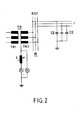
- Fig. 2 eine Schaltung, die im wesentlichen einen Teil der Schaltung aus Fig. 2 zeigt und die die Bestimmung der kapazitiven Ströme im Netz zur Einstellung der automatischen Löschspulenregulierung darstellt.
- Fig. 1 shows the arrangement with a busbar and an earth fault, in the lower part of Fig. 1, the inventive device for regulating the quenching coil and in the upper part, for example, a circuit arrangement for selective earth fault indication is shown, and
- FIG. 2 shows a circuit which essentially shows part of the circuit from FIG. 2 and which represents the determination of the capacitive currents in the network for setting the automatic quenching coil regulation.
Gemäss Fig. 1 weist ein Transformator TR eine Primärseite TR1 und eine Sekundärseite TR2 in Sternschaltung auf. Der Nullpunkt der Sekundärseite TR2 ist über eine Löschspule L geerdet, die Ausgänge der Sekundärseite TR2 sind an die Sammelschiene W der Phasen R, S, T und somit auch an die zugehörigen dreiphasigen Linien 1, 2, 3 des Netzes angeschlossen. Jede der drei Linien 1, 2, 3 ist mit je einem Summenstromwandler S1, S2, S3 versehen. Mit ΣIS1 bis EIS3 sind die Ströme in den Summenstromwandlern Sr bis S3 bezeichnet. Die Kapazitäten CE zwischen den Linien 1, 2, 3 und der Erde sind als Kondensatoren symbolisch dargestellt. Ein Erdschluss E mit kapazitivem und ohmschem Strom ist in diesem Beispiel zwischen der Phase T der Linie 3 und der Erde dargestellt.1, a transformer TR has a primary side TR1 and a secondary side TR2 in star connection. The Zero point of the secondary side TR2 is grounded via an erase coil L, the outputs of the secondary side TR2 are connected to the busbar W of the phases R, S, T and thus also to the associated three-
Die Funktionsweise der selektiven Erdschlussanzeige wurde schon oben beschrieben.The functionality of the selective earth fault indicator has already been described above.
Im unteren Teil der Fig. 1 ist die erfindungsgemässe Vorrichtung zur Regulierung wenigstens einer Löschspule L in einem gelöschten mehrphasigen Netz gezeigt. Drei Digital-analog-Wandler DA1 bis DA3 sind in diesem Beispiel den Linien 1 bis 3 zugeordnet, wobei die weiteren Linien 4 bis z.B. 14 und die weiteren Digital-analog-Wandler 4 bis z.B. Digital-analog-Wandler 14 in der Zeichnung nicht dargestellt sind. Diese Digital-analog-Wandler DA1 bis DA3 arbeiten im Bereich 0 bis 99 %. Jeder dieser Wandler ist an zwei Codierschalter angeschlossen. Diese Kodierschalter sind je für "Zehner" und "Einer" bestimmt. In dem gezeigten Beispiel zeigt der erste Digital-analog-Wandler DA1 also 10 %, der zweite Digital-analog-Wandler DA2 00 % und der dritte Digital-analog-Wandler DA3 15 %. Die Summe aller Werte für z.B. 14 Linien bildet 100 %. Diese drei Digital-analog-Wandler sind an einen Summierverstärker SV angeschlossen, der mit dem Erdschlusskriterium EK verbunden ist und der weiter an einen Vergleicher VG angeschlossen ist. Die Einstellung der Löschspule L ist über einen Winkeltransmitter WT und über eine galvanische Trennung GT in den Vergleicher VG geleitet. Der Vergleicher VG steuert eine Relais-Anordnung RA, die an einen Motorantrieb M angeschlossen ist. Dieser Motorantrieb M dient zur Einstellung der Löschspule L. Die Relais-Anordnung RA kann auch im Handbetrieb arbeiten. Diese Möglichkeit ist mit dem Pfeil H angedeutet. Der Vergleicher VG mit dem Summierverstärker SV, mit dem Erdschlusskriterium EK und und mit der Relais-Anordnung RA bilden die eigentliche Löschspulenregulierung LR. Die Funktionsweise dieser Anordnung ist schon oben beschrieben worden. Um die gewünschte Unter- oder Überkompensation zu erreichen, wird die Verstärkung des Summierverstärkers SV durch das Erdschlusskriterium EK beeinflusst.In the lower part of FIG. 1, the device according to the invention for regulating at least one quenching coil L in a quenched multiphase network is shown. In this example, three digital-to-analog converters DA1 to DA3 are assigned to
In Fig. 2 ist eine Schaltung aufgezeigt, anhand dieser die Ermittlung und/oder die Berechnung des Sollwertes erläutert wird.2 shows a circuit by means of which the determination and / or the calculation of the target value is explained.
Gemäss Fig. 2 wird eine Linie, in diesem Fall die Linie 1, manuell auf eine Sammelschiene W separat geschaltet. Diese Schaltanordnung dient zur Bestimmung der kapazitiven Ströme im Netz zur Einstellung der automatischen Löschspulenregulierung. Die kapazitiven Ströme der einzelnen Linien werden der Automatik prozentual als Sollwert eingegeben. Um die kapazitiven Ströme feststellen zu können, stellt man die Löschspule L auf Resonanz, d.h. auf das Maximum der Spannung an der Löschspule L, und liest nun den Strom auf der geeichten Löschspule-Stellungsskala ab.According to FIG. 2, a line, in this
Wenn man den Löschspul-Strom bei gesundem Netz mit ILO bezeichnet, die Löschspulenspannung bei gesundem Netz mit ULO, die Netzspannung bei gesundem Netz mit U und den kapazitiven Strom bei Erdschluss mit IC, erhält man folgende Gleichung:
Die automatische Regulierung gemäss der vorliegenden Erfindung weist also vorallem zwei Vorteile auf: bei einem System mit mehreren Sammelschienen können sich die Automatiken nicht beeinflussen und es wird auch das Einstellkriterium bei einem eintretenden Erdschluss nicht verloren, und somit werden weggeschaltete Netzteile nachgeregelt.The automatic regulation according to the present invention therefore has two advantages in particular: in a system with a plurality of busbars, the automatics cannot influence one another and the setting criterion is not lost in the event of an earth fault, and thus disconnected power supplies are readjusted.
- TR = TransformatorTR = transformer
- TR1 = Primärseite des Transformators TRTR1 = primary side of the transformer TR
- TR2 = Sekundärseite des Transformators TRTR2 = secondary side of the transformer TR
- L = LöschspuleL = quenching coil
- R, S, T = Phasen des NetzesR, S, T = phases of the network
- W = SammelschieneW = busbar
- 1, 2, 3 = Linien des Netzes1, 2, 3 = lines of the network
-
S1, S2, S3 = Summenstromwandler der Linien 1, 2, 3S1, S2, S3 = total current transformers of
lines -
CE = Kapazitäten zwischen den Linien 1, 2, 3 und der ErdeCE = capacities between
lines - E = Erdschluss mit kapazitivem und ohmschem StromE = earth fault with capacitive and ohmic current
- ΣIS1 bis ΣIS3 = Ströme in den Summenstromwandlern S1 bis S3ΣI S1 to ΣI S3 = currents in the summation current transformers S1 to S3
- DA1 bis DA3 = Digital-analog-WandlerDA1 to DA3 = digital-to-analog converter
- 10, 00, 15 = Angaben der Codierschalter10, 00, 15 = code switch information
- SV = Summierverstärker mit variabler VerstärkungSV = summing amplifier with variable gain
- EK = ErdschlusskriteriumEK = earth fault criterion
- VG = VergleicherVG = comparator
- RA = Relais-AnordnungRA = relay arrangement
- H = HandsteuerbetriebH = manual control mode
- LR = LöschspulenregulierungLR = quenching coil regulation
- GT = galvanische TrennungGT = galvanic isolation
- WT = WinkeltransmitterWT = angle transmitter
- M = MotorantriebM = motor drive
- V = SpannungsmesserV = voltmeter
- A = StrommesserA = ammeter
Claims (15)

Priority Applications (1)
| Application Number | Priority Date | Filing Date | Title |
|---|---|---|---|
| AT82810553T ATE18833T1 (en) | 1981-12-22 | 1982-12-20 | METHOD AND DEVICE FOR ADJUSTING AT LEAST ONE EXTINGUISHING COIL IN A MULTIPHASE NETWORK. |
Applications Claiming Priority (4)
| Application Number | Priority Date | Filing Date | Title |
|---|---|---|---|
| CH8183/81 | 1981-12-22 | ||
| CH818381 | 1981-12-22 | ||
| CH7201/82 | 1982-12-10 | ||
| CH720182 | 1982-12-10 |
Publications (2)
| Publication Number | Publication Date |
|---|---|
| EP0083306A1 true EP0083306A1 (en) | 1983-07-06 |
| EP0083306B1 EP0083306B1 (en) | 1986-03-26 |
Family
ID=25700926
Family Applications (1)
| Application Number | Title | Priority Date | Filing Date |
|---|---|---|---|
| EP19820810553 Expired EP0083306B1 (en) | 1981-12-22 | 1982-12-20 | Process and device to control at least one compensation coil in a polyphase network |
Country Status (2)
| Country | Link |
|---|---|
| EP (1) | EP0083306B1 (en) |
| DE (1) | DE3270183D1 (en) |
Cited By (6)
| Publication number | Priority date | Publication date | Assignee | Title |
|---|---|---|---|---|
| FR2616228A1 (en) * | 1987-06-04 | 1988-12-09 | Merlin Gerin | DEVICE FOR MONITORING AND MEASURING THE INSULATION OF AN ELECTRICAL NETWORK |
| WO1992018872A1 (en) * | 1991-04-19 | 1992-10-29 | Elektro-Bau Ag | Process for detecting a branch circuit subject to earth leaks in an electric power supply or distribution system |
| AT404072B (en) * | 1995-02-28 | 1998-08-25 | Haefely Trench Austria Gmbh | METHOD FOR DETECTING A SINGLE-POLE EARTH FAULT IN A THREE-PHASE NETWORK |
| CN107340408A (en) * | 2017-07-26 | 2017-11-10 | 国网河南省电力公司洛阳供电公司 | Capacitance current generator is used in a kind of arc suppression coil debugging |
| CN112858832A (en) * | 2019-11-12 | 2021-05-28 | 安徽帕维尔智能技术有限公司 | Large-current line selection method based on arc suppression coil grounding system |
| CN113341246A (en) * | 2021-05-24 | 2021-09-03 | 国网陕西省电力公司西安供电公司 | Arc suppression coil testing device and method based on capacitance calibration |
Families Citing this family (2)
| Publication number | Priority date | Publication date | Assignee | Title |
|---|---|---|---|---|
| CN106802361B (en) * | 2017-02-21 | 2019-03-29 | 国家电网公司 | A kind of capacitance current measurement method and system of distribution mixed connection ground connection operation |
| CN111030063B (en) * | 2019-12-09 | 2022-02-01 | 中国南方电网有限责任公司超高压输电公司检修试验中心 | Segmented time domain capacitance current compensation method |
Citations (5)
| Publication number | Priority date | Publication date | Assignee | Title |
|---|---|---|---|---|
| DE399136C (en) * | 1920-04-16 | 1924-07-26 | Asea Ab | Self-changing zero point choke coil for high voltage networks |
| DE760151C (en) * | 1941-08-13 | 1954-02-22 | Brown Ag | Device for the automatic setting of a loeschinductivity used for earth fault protection in an alternating current network when the partial capacity of the network changes to earth |
| FR1057276A (en) * | 1952-05-23 | 1954-03-08 | Merlin Gerin | Selective network fault detector |
| FR2161752A1 (en) * | 1971-10-27 | 1973-07-13 | Edf | |
| DE2400527A1 (en) * | 1973-01-08 | 1974-08-15 | Knudsen Nordisk Elect | PROCEDURE FOR DETERMINING INSULATION FAULTS IN ELECTRICAL DISTRIBUTION NETWORKS |
-
1982
- 1982-12-20 EP EP19820810553 patent/EP0083306B1/en not_active Expired
- 1982-12-20 DE DE8282810553T patent/DE3270183D1/en not_active Expired
Patent Citations (5)
| Publication number | Priority date | Publication date | Assignee | Title |
|---|---|---|---|---|
| DE399136C (en) * | 1920-04-16 | 1924-07-26 | Asea Ab | Self-changing zero point choke coil for high voltage networks |
| DE760151C (en) * | 1941-08-13 | 1954-02-22 | Brown Ag | Device for the automatic setting of a loeschinductivity used for earth fault protection in an alternating current network when the partial capacity of the network changes to earth |
| FR1057276A (en) * | 1952-05-23 | 1954-03-08 | Merlin Gerin | Selective network fault detector |
| FR2161752A1 (en) * | 1971-10-27 | 1973-07-13 | Edf | |
| DE2400527A1 (en) * | 1973-01-08 | 1974-08-15 | Knudsen Nordisk Elect | PROCEDURE FOR DETERMINING INSULATION FAULTS IN ELECTRICAL DISTRIBUTION NETWORKS |
Cited By (10)
| Publication number | Priority date | Publication date | Assignee | Title |
|---|---|---|---|---|
| FR2616228A1 (en) * | 1987-06-04 | 1988-12-09 | Merlin Gerin | DEVICE FOR MONITORING AND MEASURING THE INSULATION OF AN ELECTRICAL NETWORK |
| EP0297933A1 (en) * | 1987-06-04 | 1989-01-04 | Merlin Gerin | Apparatus to check and to measure the insulation of an electric network |
| US4896115A (en) * | 1987-06-04 | 1990-01-23 | Merlin Gerin | Electrical network insulation monitoring and measuring device |
| WO1992018872A1 (en) * | 1991-04-19 | 1992-10-29 | Elektro-Bau Ag | Process for detecting a branch circuit subject to earth leaks in an electric power supply or distribution system |
| AT404072B (en) * | 1995-02-28 | 1998-08-25 | Haefely Trench Austria Gmbh | METHOD FOR DETECTING A SINGLE-POLE EARTH FAULT IN A THREE-PHASE NETWORK |
| CN107340408A (en) * | 2017-07-26 | 2017-11-10 | 国网河南省电力公司洛阳供电公司 | Capacitance current generator is used in a kind of arc suppression coil debugging |
| CN107340408B (en) * | 2017-07-26 | 2023-06-09 | 国网河南省电力公司洛阳供电公司 | Capacitor current generator for arc suppression coil adjustment |
| CN112858832A (en) * | 2019-11-12 | 2021-05-28 | 安徽帕维尔智能技术有限公司 | Large-current line selection method based on arc suppression coil grounding system |
| CN113341246A (en) * | 2021-05-24 | 2021-09-03 | 国网陕西省电力公司西安供电公司 | Arc suppression coil testing device and method based on capacitance calibration |
| CN113341246B (en) * | 2021-05-24 | 2024-02-06 | 国网陕西省电力公司西安供电公司 | Arc suppression coil testing device and method based on capacitance calibration |
Also Published As
| Publication number | Publication date |
|---|---|
| EP0083306B1 (en) | 1986-03-26 |
| DE3270183D1 (en) | 1986-04-30 |
Similar Documents
| Publication | Publication Date | Title |
|---|---|---|
| DE2256536A1 (en) | PROCEDURE AND ARRANGEMENT FOR LOCATING A FAULT ON AN ELECTRIC POWER TRANSPORT LINE | |
| EP0083306B1 (en) | Process and device to control at least one compensation coil in a polyphase network | |
| DE3608082A1 (en) | Circuit arrangement for stabilising the output DC voltage with a varying input DC voltage of a step-down/step-up controller combination | |
| DE4428118A1 (en) | Earth fault location in electrical networks with an earth fault coil | |
| DE3326947A1 (en) | METHOD AND CIRCUIT FOR OPERATING A HIGH VOLTAGE DC CONNECTION BETWEEN TWO AC VOLTAGE NETWORKS | |
| DE2607328C3 (en) | Control and monitoring circuit for three-phase point machines | |
| DE1932392A1 (en) | Control device for electrical load | |
| CH661384A5 (en) | ARRANGEMENT FOR CONTROLLING A TRANSMISSION SYSTEM FOR HIGH-VOLTAGE DC. | |
| DE2615034C2 (en) | Test device for primary testing of voltage, current and frequency relays | |
| DE3005185C2 (en) | Reactive power regulator | |
| EP0037087A1 (en) | Method and device for connecting and disconnecting without overoscillation a capacitor between two conductors of an AC network | |
| DE4036062C2 (en) | Power supply with regulated output voltage | |
| DE3122042C2 (en) | Procedure and test circuit for earth fault testing of voltage-free cable routes | |
| DE4335847C2 (en) | Test device for load testing an electricity generator | |
| AT524958B1 (en) | Procedure for determining network parameters for controlling a Petersen coil | |
| DE3132933A1 (en) | Arrangement for determining the winding currents required for compensation in magnetic self-protection systems | |
| WO1992018872A1 (en) | Process for detecting a branch circuit subject to earth leaks in an electric power supply or distribution system | |
| DE102016222295A1 (en) | Substation, railway power plant and method for feeding at least one single-phase supply line | |
| DE1541742C3 (en) | Device for monitoring the total insulation resistance of an electrical network to earth or ground | |
| DE699324C (en) | Arrangement for loading an alternating current network with controllable reactive currents | |
| AT225298B (en) | Control arrangement for load compensation in the case of several electrical devices, in particular rectifier devices, which feed a common consumer and are regulated to a constant output voltage | |
| DE2501556C3 (en) | Procedure for the transmission of different information | |
| DE479112C (en) | Device for changing the power factor in a network of any number of phases, which is to be kept constant by a phase regulator | |
| DE930038C (en) | Method and arrangement for fine control of an alternating voltage | |
| DE700223C (en) | Step transformer |
Legal Events
| Date | Code | Title | Description |
|---|---|---|---|
| PUAI | Public reference made under article 153(3) epc to a published international application that has entered the european phase |
Free format text: ORIGINAL CODE: 0009012 |
|
| AK | Designated contracting states |
Designated state(s): AT BE CH DE FR GB IT LI LU NL SE |
|
| 17P | Request for examination filed |
Effective date: 19830530 |
|
| ITF | It: translation for a ep patent filed |
Owner name: ING. ZINI MARANESI & C. S.R.L. |
|
| GRAA | (expected) grant |
Free format text: ORIGINAL CODE: 0009210 |
|
| AK | Designated contracting states |
Kind code of ref document: B1 Designated state(s): AT BE CH DE FR GB IT LI LU NL SE |
|
| REF | Corresponds to: |
Ref document number: 18833 Country of ref document: AT Date of ref document: 19860415 Kind code of ref document: T |
|
| REF | Corresponds to: |
Ref document number: 3270183 Country of ref document: DE Date of ref document: 19860430 |
|
| ET | Fr: translation filed | ||
| PLBE | No opposition filed within time limit |
Free format text: ORIGINAL CODE: 0009261 |
|
| STAA | Information on the status of an ep patent application or granted ep patent |
Free format text: STATUS: NO OPPOSITION FILED WITHIN TIME LIMIT |
|
| 26N | No opposition filed | ||
| REG | Reference to a national code |
Ref country code: CH Ref legal event code: PUE Owner name: SPRECHER ENERGIE AG |
|
| ITPR | It: changes in ownership of a european patent |
Owner name: CESSIONE;SPRECHER ENERGIE AG |
|
| REG | Reference to a national code |
Ref country code: FR Ref legal event code: TP |
|
| REG | Reference to a national code |
Ref country code: GB Ref legal event code: 732 |
|
| NLS | Nl: assignments of ep-patents |
Owner name: SPRECHER ENERGIE AG TE OBERENTFELDEN, ZWITSERLAND. |
|
| PGFP | Annual fee paid to national office [announced via postgrant information from national office to epo] |
Ref country code: FR Payment date: 19911115 Year of fee payment: 10 |
|
| PGFP | Annual fee paid to national office [announced via postgrant information from national office to epo] |
Ref country code: GB Payment date: 19911118 Year of fee payment: 10 Ref country code: DE Payment date: 19911118 Year of fee payment: 10 |
|
| PGFP | Annual fee paid to national office [announced via postgrant information from national office to epo] |
Ref country code: CH Payment date: 19911119 Year of fee payment: 10 |
|
| PGFP | Annual fee paid to national office [announced via postgrant information from national office to epo] |
Ref country code: BE Payment date: 19911120 Year of fee payment: 10 |
|
| PGFP | Annual fee paid to national office [announced via postgrant information from national office to epo] |
Ref country code: SE Payment date: 19911122 Year of fee payment: 10 |
|
| PGFP | Annual fee paid to national office [announced via postgrant information from national office to epo] |
Ref country code: AT Payment date: 19911126 Year of fee payment: 10 |
|
| PGFP | Annual fee paid to national office [announced via postgrant information from national office to epo] |
Ref country code: LU Payment date: 19911129 Year of fee payment: 10 |
|
| ITTA | It: last paid annual fee | ||
| PGFP | Annual fee paid to national office [announced via postgrant information from national office to epo] |
Ref country code: NL Payment date: 19911231 Year of fee payment: 10 |
|
| EPTA | Lu: last paid annual fee | ||
| PG25 | Lapsed in a contracting state [announced via postgrant information from national office to epo] |
Ref country code: LU Free format text: LAPSE BECAUSE OF NON-PAYMENT OF DUE FEES Effective date: 19921220 Ref country code: GB Effective date: 19921220 Ref country code: AT Effective date: 19921220 |
|
| PG25 | Lapsed in a contracting state [announced via postgrant information from national office to epo] |
Ref country code: SE Effective date: 19921221 |
|
| PG25 | Lapsed in a contracting state [announced via postgrant information from national office to epo] |
Ref country code: LI Effective date: 19921231 Ref country code: CH Effective date: 19921231 Ref country code: BE Effective date: 19921231 |
|
| BERE | Be: lapsed |
Owner name: SPRECHER ENERGIE A.G. Effective date: 19921231 |
|
| PG25 | Lapsed in a contracting state [announced via postgrant information from national office to epo] |
Ref country code: NL Effective date: 19930701 |
|
| NLV4 | Nl: lapsed or anulled due to non-payment of the annual fee | ||
| GBPC | Gb: european patent ceased through non-payment of renewal fee |
Effective date: 19921220 |
|
| PG25 | Lapsed in a contracting state [announced via postgrant information from national office to epo] |
Ref country code: FR Effective date: 19930831 |
|
| REG | Reference to a national code |
Ref country code: CH Ref legal event code: PL |
|
| PG25 | Lapsed in a contracting state [announced via postgrant information from national office to epo] |
Ref country code: DE Effective date: 19930901 |
|
| REG | Reference to a national code |
Ref country code: FR Ref legal event code: ST |
|
| EUG | Se: european patent has lapsed |
Ref document number: 82810553.6 Effective date: 19930709 |