EP0481865B1 - Induktionsringbeschleuniger für Bohrlochmessungen - Google Patents
Induktionsringbeschleuniger für Bohrlochmessungen Download PDFInfo
- Publication number
- EP0481865B1 EP0481865B1 EP91402734A EP91402734A EP0481865B1 EP 0481865 B1 EP0481865 B1 EP 0481865B1 EP 91402734 A EP91402734 A EP 91402734A EP 91402734 A EP91402734 A EP 91402734A EP 0481865 B1 EP0481865 B1 EP 0481865B1
- Authority
- EP
- European Patent Office
- Prior art keywords
- coil
- core
- accelerator
- magnet
- orbit
- Prior art date
- Legal status (The legal status is an assumption and is not a legal conclusion. Google has not performed a legal analysis and makes no representation as to the accuracy of the status listed.)
- Expired - Lifetime
Links
Images


Classifications
-
- H—ELECTRICITY
- H05—ELECTRIC TECHNIQUES NOT OTHERWISE PROVIDED FOR
- H05H—PLASMA TECHNIQUE; PRODUCTION OF ACCELERATED ELECTRICALLY-CHARGED PARTICLES OR OF NEUTRONS; PRODUCTION OR ACCELERATION OF NEUTRAL MOLECULAR OR ATOMIC BEAMS
- H05H11/00—Magnetic induction accelerators, e.g. betatrons
-
- H—ELECTRICITY
- H05—ELECTRIC TECHNIQUES NOT OTHERWISE PROVIDED FOR
- H05H—PLASMA TECHNIQUE; PRODUCTION OF ACCELERATED ELECTRICALLY-CHARGED PARTICLES OR OF NEUTRONS; PRODUCTION OR ACCELERATION OF NEUTRAL MOLECULAR OR ATOMIC BEAMS
- H05H7/00—Details of devices of the types covered by groups H05H9/00, H05H11/00, H05H13/00
- H05H7/04—Magnet systems, e.g. undulators, wigglers; Energisation thereof
Definitions
- the present invention relates generally to particle accelerator sources for borehole applications and, more particularly, to a circular magnetic induction accelerator (betatron) for borehole use.
- a circular magnetic induction accelerator betatron
- High energy electromagnetic radiation sources are used in well logging for various applications, most principally for measuring the bulk density and lithology of earth formations.
- the current state of the commercial art in formation density logging tools is to use a radioactive (chemical) source, usually137Cs, two gamma ray detectors, typically NaI, with suitable data processing circuitry and algorithms to derive mudcake and/or standoff-compensated density measurements.
- a photoelectric effect P e measurement may also be made from the low energy part of the gamma ray energy spectrum from the density tool detectors, from which information about the lithology of a formation may be derived.
- radioactive source in such tools, however, gives rise to radiological safety hazards during use, transportation and storage of the tools. Also, the maximum energy and radiation fluxes attainable with radioactive sources are limited by the size and type of the source, which parameters are also affected by the aforementioned safety and handling considerations. Moreover, as radioactive sources emit photons continuously and isotropically, they are not readily usable for timed or focused measurements.
- Linear accelerators of the standing wave type are disclosed for this purpose in, for example, U.S. Patent No. 3,976,879 to Turcotte, U.S. Patent No. 4,093,854 to Turcotte et al., and U.S. Patent No. 4,713,581 to Haimson. While such linear accelerators afford advantages relative to radioactive sources with respect to radiological safety, higher flux and energy outputs, and pulsed operation, they are comparatively expensive to manufacture and maintain. Their complexity and lack of reliability are also drawbacks.
- This device employs a toroidal magnetic field in addition to the conventional betatron field to increase the circulating electron current.
- the elongated structure means that the magnetic field needs to fill a larger volume than does a conventional betatron of comparable energy.
- the excitation energy per pulse is higher and the repetition rate is lower than in circular induction betatrons; a disadvantage.
- the elongated structure makes flux containment difficult in the borehole geometry.
- focusing is typically achieved by using tow opposed magnet poles to provide a magnetic field traversing the substantially circular electron orbit between the poles. This type of focusing is quite weak, and by itself does not permit sufficient electron charge to be trapped and accelerated to the full desired energy. Auxiliary focusing, while useful in surface betatrons, is not practical for borehole applications because of space limitations in the borehole.
- V.V.Vasil'ev and E. G. Furman: Magnetic System of Betatron with Auxiliary Magnetization, Instruments and Experimental Techniques, Vol. 25 (1982), No.1, Part 1, pp.26-28 describes a betatron magnetic system comprising a central ferromagnetic core and an electromagnet with a space between the poles thereof, surrounded by an excitation winding.
- the required distribution of magnetic fluxes is effected by a compensating screening winding placed in slots around the core and loaded by an inductor in the form of an annular winding consisting of two halves.
- US Patent No. 2,754,419 describes a magnetic induction accelerator comprising a magnetic field structure, two coils providing the main flux and the control or guiding flux, and an annular tube inside which electrons are accelerated. Pole shoes are provided with two expansion or contraction coils which are connected in series.
- a compact circular magnetic induction accelerator, or betatron adapted for use in a borehole includes a magnetic circuit having a field magnet and generally circular opposed pole pieces composed of a class of ferrite having the general formula M+Fe 2 3+ O4, where M represents two or more divalent metal ions from the group consisting of Mn, Zn and Ni.
- the core magnet is comprised of one or more closed loop sections, with one leg of each loop extending axially through the center of the circular pole pieces.
- the core magnet comprises two symmetrically arranged closed loops.
- the core magnet is made of a low magnetic loss material, and preferably from multiple wound layers of a metallized tape such as Metglass tape or from a combination of Metglass tape and ferrite. This construction and composition of the field and core magents maximizes the saturation flux density and charge retention capacity of the magnetic circuit within the space constraints of the borehole environment.
- the excitation circuits may be arranged with the field magnet coil and the core magnet coil coupled either in parallel or in series.
- various techniques may be employed to control the compression and expansion of the electron beam orbits to effect beam capture and ejection.
- a switchable orbit expansion coil is preferably connected in series with either or both the field coil and the core coil, and is switched in or out of the circuit at the appropriate times in the operating cycle to disrupt the betatron flux condition and eject the electron beam from its normal circular orbit. Upon ejection, the beam strikes the target and produces high energy gamma ray photons.
- the orbit expansion coil may be tunable and also function as an orbit position tuning (OPT) coil. Alternatively, a separate OPT coil may be provided.
- beam compression and entrapment may be accomplished by means of a reverse-wound coil inductively coupled to the core magnet coil to buck the field coil flux in the core magnet.
- a brief pulse preferably square shaped, is generated in a pulse forming line inductively coupled to the core coil to abruptly break and restore the betatron condition during the electron injection and capture cycle.
- the pulse forming line can be omitted, and the required disruption of the betatron flux condition for beam injection and capture accomplished by including an OPT coil in series with the core coil and by selecting the impedance of the OPT coil core relative to that of the core magnet to produce a voltage partition transient of brief duration between the two coils upon application of the acceleration voltage pulses to the primary circuit.
- the electrons are injected simultaneously with the amplication of the acceleration voltage pulses.
- a reverse-wound coil inductively coupled to the core magnet coil, is connected in series with the field magnet coil and with the switchable orbit expansion coil.
- a switchable orbit compression coil is connected in series with the core magnet coil. The orbit compression coil is switched out of the circuit at the end of the beam injection cycle and the orbit expansion coil is switched into the circuit at the end of the beam ejection cycle, thereby disrupting the betatron flux condition to effect beam capture and ejection.
- a switch is coupled across the core coil so as, when conducting, to form a closed loop with the core coil. This disrupts the betatron flux condition in the magnetic circuit, causing the charged particles to spiral inwardly. Upon reopening of the switch, the betatron condition is restored and the particles are trapped in circular orbits. Energy efficiency is improved since the current flow in the closed loop also provides part of the ampere turns for the field magnet and thereby reduces the ampere turns supplied by the primary coil.
- An expansion coil and switch are coupled in series with the field and core coils to effect beam ejection.
- This construction eliminates the need for a reverse-wound coil to buck the core flux induced by the field coil. It also enhances the energy efficiency of the betatron and the excitation system.
- the betatron condition can be established by proper selection of the turn ratio of the field and core coils or, if desired, by provision of an OPT coil.
- the primary coil and the field coil may be combined into a common coil.
- the expansion and compression switches may be arranged so as to be conducting only during the short ejection and injection cycles and not during the main acceleration cycle. Thus not only are losses attributable to the operation of the switches reduced, but lower cost switches may be employed, affording still further economies.
- a sufficiently high end point beam energy preferably 2 MeV
- high average beam current preferably >1 ⁇ A.
- the maximum beam energy of a betatron is proportional to the area enclosed by the electron orbit as well as the saturation flux density of the material used for the induction core magnet. Because the size of the electron orbit is limited by the diameter of the well bore, achieving >2 MeV beam energy generally requires >10 KGauss saturation flux density for the induction core magnet.
- the accelerator must be operated at a high repetition rate, eg in the range of several KHz. It is also important that the desired beam energy and beam current be attained at a power level within the feasibility of downhole logging tools. This may be on the order of 2 KW, but is preferably 1 KW or less.
- Fig. 1 illustrates the basic magnetic circuit and coil structure of a compact betatron which meets the foregoing criteria.
- the core magnet 10 is comprised of symmetrical closed-loop sections 10a and 10b made of built-up layers of a low magnetic loss metallical tape, such as Metglass, which is commercially available from the Magnetics Division of Spang Industries, Inc. and other suppliers.
- the sections 10a and 10b are preferably circular or rounded in cross section (see Fig. 2) and are also rounded at the corners (see Fig. 1).
- the core may be made up of a composite of Metglass tape and a ferrite, e.g. a Ni-Zn ferrite, although this will result in the core having a somewhat lower saturation flux density.
- both the field magnet 12 and the pole pieces 14a and 14b are composed of a class of ferrite having the general formula M+Fe 2 3+ O4, where M represents two or more divalent metal ions from the group consisting of manganese, zinc and nickel.
- Mn-Zn ferrites are made from mixtures of MnO, ZnO and Fe2O3, and Ni-Zn ferrites are made from mixtures of NiO, ZnO and Fe2O3).
- Mn-Zn ferrites are made from mixtures of MnO, ZnO and Fe2O3
- Ni-Zn ferrites are made from mixtures of NiO, ZnO and Fe2O3
- the acceleration chamber is preferably evacuated to 5x10 ⁇ 9 mm of Hg or less.
- the field coil 20 Externally of the chamber 16 and surrounding both the pole pieces 14a and 14b and the central axial legs 18a and 18b of the core magnet 10 is the field coil 20. So wound, the field coil induces a magnetic flux in both the field magnet 12 ( ⁇ f ) and the core magnet 10 ( ⁇ c ). As described more fully hereinafter, a core winding or coil 22, surrounding only the axial core legs 18a and 18b, is connected in parallel (Figs. 4, 6 and 7) or in series (Figs. 8-11) with the field coil 20. Both coils 20 and 22, as well as all other windings, are preferably single layer windings to avoid the capacitive coupling effects induced between the turns of multiple layer coils.
- Electrons injected into the chamber 16 are trapped therein by the applied magnetic field and are guided along generally circular orbital paths until the desired end point energy is achieved and are then ejected.
- electrons are injected into the vacuum chamber 16 by an injector 26 which extends through a port in the chamber wall.
- the betatron condition is again upset and the electron beam is kicked out, or ejected, from the orbit 24 so as to impact against a target 28, thereby producing a flux of high energy gamma ray photons.
- the injector 26, target 28 and the associated structural and electrical connections are conventional.
- a high voltage D.C. power supply 30 is coupled across a capacitor 32 to modulator circuits 34 which pulse the primary betatron coil circuits 36 at the desired repetition rate with time-varying acceleration voltage pulses.
- modulator circuits 34 which pulse the primary betatron coil circuits 36 at the desired repetition rate with time-varying acceleration voltage pulses.
- the energy stored in the capacitor 32 is transferred to the betatron magnets through a switching network (not shown), and at the end of each cycle the remaining energy in the magnets is returned to the capacitor 32 through a recovery network (not shown).
- Losses in the system are replenished by the power supply 30, which for that purpose must have an output voltage equal to or greater than the maximum voltage intended for the capacitor 32.
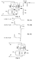
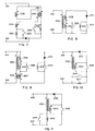
- Figs. 4 and 6-11 which illustrate representative embodiments of the betatron coil circuits 36 in accordance with the invention
- the solid parallel lines opposite the coils indicate the core magnet and the dashed parallel lines indicate the field magnet.
- the dots adjacent the ends of the respective coils indicate the winding orientation of the coils.
- the field coil 38 is coupled in parallel to the core coil 40, surrounding only the core, between the nodes 41 of the primary circuit.
- an orbit expansion, or beam ejection, circuit including an expansion coil 42 and a normally-closed switch 44.
- an orbit position tuning (OPT) coil 46 may be provided in series with the core coil 40 or the field coil 38 to facilitate establishment of the betatron condition and adjustment of the electron orbit radius.
- OPT orbit position tuning
- a reverse-wound coil 48 is inductively coupled to the core coil 40 to offset the core magnet flux induced by the field coil 38, thereby decoupling the field coil 38 from the core magnet.
- Another coil 54, wound on the core is coupled to a pulse forming network (PFN) 52 which, with coil 54 as its last stage, has an impedance 56.
- PPN pulse forming network
- a conventional dc coil (not shown) provides a proper magnetic field in the orbital region which causes electrons to circulate in an orbit of constant radius before any voltage is applied to terminals 41.
- the switch 58 is closed and a sharp current pulse, indicated at 50 in Fig. 5A, is passed through coil 54.
- the rise and fall of the current pulse induces two voltage spikes across coil 54, shown at 60a and 60b in Fig. 5B.
- the negative going pulse 60B decelerates electrons. Since the applied magnetic field is maintained at a constant value during this time, this causes the electrons to spiral inwardly as illustrated in Fig. 2.
- the injection process terminates as the main acceleration voltage pulse 70 is applied to terminals 41. (See Fig.
- the decelerating pulse 60b should be of relatively high amplitude and of sufficient duration to force the electrons inwardly quickly enough and far enough that they will not hit the target 28 in subsequent revolutions.
- the deceleration pulse 60b should also have a very sharp cut-off, preferably less that 10 nanoseconds, to prevent the electrons from spiralling into the inner wall of the acceleration chamber.
- the main acceleration pulse 70 must have a very fast rise time.
- the orbit expansion switch 44 is closed, shunting the coil 42 so that the magnetic flux between the pole pieces 14a and 14b is controlled by the voltage across the field coil 38, the core coil 40 and, if present, the OPT coil 46.
- the orbit expansion switch 44 When it is desired to extract the electron beam in Fig. 4, the orbit expansion switch 44 is abruptly opened to bring the expansion coil 42 into series with the field coil 38. This produces a sudden voltage transient in the field coil and disrupts the betatron condition, kicking the electron beam out of orbit and into contact with the target 28.
- the field coil 138, core coil 140, expansion coil 142 and switch 144, and OPT coil 146 and reverse-wound coil 148 are similar to their counterparts in Fig. 4.
- Electrons are ejected into the acceleration chamber simultaneously with the application of the acceleration voltage pulses to the nodes 141 of the primary betatron coil circuits.
- the inductance of coil 140 which is wound on a closed core, is much higher than the inductance of coil 146 which is a solenoid with an adjustable iron slug.
- most of the voltage applied to nodes 141 should appear across coil 140. This, however, is not true during the initial transient period. In fact, immediately after the voltage is applied to nodes 141, a voltage spike occurs across the OPT coil 146, disrupting the betatron condition for the duration of the transient and causing the injected electrons to spiral inwardly.
- the duration of the transient condition is dependent on the response time of the core magnet material relative to that of the OPT coil core material.
- the betatron condition must be reestablished before the electrons spiral into the inner chamber wall. It has been found that the use of Mn-Zn ferrite for both the betatron core and the OPT core provides a response time on the order of 50 nanoseconds, and that this is fast enough to achieve proper beam compression and capture.
- the duration of the transient voltage partition between the OPT coil 146 and the core coil 140 is a function of the relative impedance between the two coils, which in turn is a function of the material composition and geometry of the cores.
- the field coil 238, the reverse wound coil 248, the OPT coil 246 and the expansion coil 242 are all connected in series.
- a normally-closed orbit expansion switch 244 bridges the expansion coil 242.
- the core coil 240 and an orbit compression coil 256 and switch 258 are connected in parallel to the coils 238, 248, 246 and 242.
- the orbit expansion switch 244 is closed during both electron injection and acceleration, whereas the orbit compression switch 258 is open during injection and closed during acceleration and expansion.
- the acceleration voltage pulses are applied across the nodes 241 with compression switch 258 open.
- the inherent capacitance of switch 258, in conjunction with coils 256 and 240 causes the voltage across coil 240 to oscillate.
- the voltage across coil 240 can be made to go to zero or negative while the magnetic field in the orbit region rises steadily due to the applied voltage to nodes 241, thereby disrupting the betatron condition and causing the electrons to spiral inwardly.
- the switch 258 is thereupon closed, preferably when the voltage across 240 is zero or negative, forcing the voltage onto the core coil 240 and restoring the betatron condition to capture the electron beam.
- the OPT coil 246 and the expansion coil 242 and switch 244 function as described in connection with Fig. 4.
- Fig. 7 provides for active beam compression and capture, but without a separate pulse forming line as in Fig. 4. Because the orbit expansion and compression switches in Figs. 4, 6 and 7 are conducting during the acceleration cycle, they must be able to withstand the primary excitation energy applied to the betatron circuits.
- Figs. 8-11 depict still other embodiments of the betatron coil and control circuits, in which the coils driving the field magnet and the core magnet are connected in series and in which the need for a reverse-wound coil to buck the field coil is eliminated. Because of the gap in the field magnet circuit, the inductance of the field coil is much lower than that of the core coil which is wound on a closed loop. Thus, the inductance of the betatron is much lower in a parallel connection, such as those shown in Figs. 4, 6 and 7, than in a series connection.
- the coil 360 is the primary drive coil. IT and the field coil 338 surround both the field and the core magnets.
- the switch 344 is closed and switch 358 is open.
- the betatron condition is enforced by the requirement that the sum of voltages across the core coil 340 and the field 338 be equal to zero. If the field magnet is so designed that the betatron condition can be established by properly selecting the turn ratio of coils 338 and 340, no additional OPT coil is necessary.
- the coil 342 and the associated switch 344 are for orbit expansion purposes. If, for any reason, small orbit adjustments are necessary, an OPT coil can be inserted into the circuit.
- the OPT coil consists of a primary coil 446 and a secondary coil 447, the turn ratio of which is the same as the turn ratio between the coils 460 and 438.
- the two coils can be combined into a single coil to simplify the circuit complexity, as shown in Fig. 10.
- Figs. 8 and 10 are otherwise equivalent electrically.
- the circuit depicted in Fig. 11 is similar to that in Fig. 10 except for the placement of the coil 642 and the switch 644. Since the same current flows through both coils 660 and 642, the voltage across coil 642 is proportional to the rate of flux change in the field magnet 638. Thus, with the switch 644 open during acceleration, the betatron condition can be established provided that coils 660, 640 and 642 have the proper number of turns.
- a positive voltage is applied across the nodes 341-641 in the circuits of Figs. 8-11.
- the switch 358-658 is initially closed in all four cases and the switch 344-644 is closed for Figs. 8-10 and open for Fig. 11. This reverse biases diode 370-670, causing it to be nonconductive. Also, the switch 358-658, when closed, forms a closed loop with the core coil 340-640. This keeps the core flux essentially unchanged. Thus, the coil 360-660 drives only the field magnet 338-638, causing the electrons to spiral inwardly away from the injector. At the end of the injection period, the switch 358-658 is opened.
- the number of turns of coil 340-640 is such that the induced voltage across coil 340-640 causes the diode to become forward biased. Thereupon, the voltage balance between the various coils (338, 340 in Fig. 8, 438, 440, 447 in Fig. 9, 560, 540 in Fig. 10, 660, 640, 642 in Fig. 11) is restored and the betatron condition is satisfied.
- the speed at which the betatron condition is established depends upon the turn-off time of the switch 358-658, the current at the time the switch opens, and the impedance between nodes 341-641. For best performance, the impedance between nodes 341-641 should be as small as possible.
- the state of the switch 344-644 in Figs. 8-11 is changed (i.e. from open to closed or vice versa). As described in connection with earlier embodiments, this disrupts the voltage balance in the circuit and causes the beam to be kicked out of the orbit against the target.
- the circuit shown in Fig. 11 has the added advantage that both switches 658 and 644 are conducting only during the short injection and ejection cycles and not during the main accelerarion cycle. The losses attributable to operation of the switches are substantially reduced. Also, since the main excitation energy does not pass through the switches 658 and 644, relatively inexpensive MOSFET switches can be used. Hence economies of cost, size, energy loss and complexity all are realized.
- a compact betatron of the foregoing type as a borehole photon source in a density logging tool is illustrated in Fig. 12.
- a downhole sonde 70 is shown suspended in an open borehole 72 covered with mudcake 74.
- An articulated arm 76 urges the sonde against the borehole wall.
- the sonde includes an accelerator section 78, which contains the betatron, and a power supply 80 and a control section 82 for the betatron.
- Other power supplies (not shown) are provided as needed for the other downhole components, as is conventional.
- the control section 82 contains the modulator circuits and other circuits, as shown in Figs. 3-7, needed to drive the betatron.
- a detector section 84 is spaced from the accelerator section 78 and is shielded therefrom by a gamma ray absorber 86.
- the detector section preferably includes two or more gamma ray detectors spaced at different distances from the accelerator 78.
- Both the control section 82 and the detector section 84 are connected to a downhole signal processing and telemetry section 88, which interfaces over the logging cable 90 with surface signal processing and telemetry circuits 92.
- the circuits 92 are connected to a truck or skid-mounted computer 94 for processing of the short-spacing and long-spacing detector data to calculate borehole and mudcake-compensated bulk density measurements.
- a recorder/plotter 96 which makes the customary visual and/or tape log as a function of depth in the borehole.
- the recorder/plotter 96 is coupled to a cable-follower mechanism 98, as illustrated schematically in Fig. 8.
- a log of the compensation factor referred to as the ⁇ curve
- This trace represents the correction made to the apparent density values computed from the long-spacing detector data.
- the computer 94 may also be programmed to measure photoelectric cross section properties from the low energy portion of the scattered gamma ray spectrum, from which information about formation lithology may be derived.
- the techniques by which bulk density values, ⁇ values, and photoelectric cross section measurements are derived from a two-detector formation density tool of the type depicted in Fig. 8 are well known in the art.
- the compact betatron of the present invention is shown as having particular usefulness as a gamma ray source for bulk density logging, it is not limited to such use, but may be used for other logging applications as well where a gamma ray source is needed. It is useful, for example, where variable gamma ray energy levels or different source spectrum shapes are desired, both of which are attainable with the borehole betatron of the invention.
Landscapes
- Physics & Mathematics (AREA)
- Engineering & Computer Science (AREA)
- Plasma & Fusion (AREA)
- Spectroscopy & Molecular Physics (AREA)
- Optics & Photonics (AREA)
- Geophysics And Detection Of Objects (AREA)
- Particle Accelerators (AREA)
- Carbon And Carbon Compounds (AREA)
- Apparatus For Radiation Diagnosis (AREA)
Claims (15)
- Ein Magnetinduktionsbeschleuniger, umfassend einen Magnetkreis einschließlich eines Kernmagneten (10), eine Erregerschaltung einschließlich Spulen (20, 22), die teilweise den Kernmagnet (10) umschließen, eine ringförmige Beschleunigungskammer (16), Mittel (30, 32, 34, 36) für das Anlegen von zeitvariablen Beschleunigungsspannungsimpulsen an die Schaltung für das Beschleunigen geladener Partikel in der Beschleunigungskammer (16), Mittel (26) für das Injizieren geladener Partikel in die Beschleunigungskammer (16), Mittel für das Komprimieren der Partikelumlaufbahnen zum Einkesseln von Partikeln innerhalb generell kreisförmiger Umlaufbahnen in der Beschleunigungskammer (16), und Mittel für das Expandieren der Partikelumlaufbahnen zum Emittieren von Partikeln aus diesen, dadurch gekennzeichnet, daß:der Magnetkreis einen Feldmagnet (12) und ein Paar von einander gegenüber angeordneten, generell kreisförmigen Polstücken (14a, 14b) umfaßt, zwischen denen die Beschleunigungskammer (16) eingefügt ist, welcher Feldmagnet (12) und welche Polstücke (14a, 14b) aus einer Klasse von Ferriten bestehen mit der generellen Formel M⁺Fe2 3+O₄, worin M zwei oder mehr divalente Metallionen von Mn, Zn und Ni repräsentiert;die Spulen eine Feldspule (20) umfassen, die die Polstücke (14a, 14b) des Feldmagneten (12) und einen Teil des Kernmagneten (10) sowie eine Kernspule (22), die einen Teil des Kernmagneten (10) umschließt, umfassen; undder Kernmagnet (10) einen oder mehrere in sich geschlossene Abschnitte (10a, 10b) umfaßt, wobei ein Schenkel (18a, 18b) des oder jedes Abschnitts axial durch das Zentrum der kreisrunden Polstücke (14a, 14b) des Feldmagneten (12) und durch die Kernspule (22) verläuft.
- Ein Beschleuniger nach Anspruch 1, bei dem der Kernmagnet (10) mindestens teilweise aus einem gewickelten Band niedrigen magnetischen Verlustes besteht.
- Ein Beschleuniger nach Anspruch 1 oder 2, bei dem der Kernmagnet (10) zwei diametral einander gegenüberliegende, in sich geschlossene Abschnitte (10a, 10b) umfaßt.
- Ein Beschleuniger nach Anspruch 1, 2 oder 3, bei dem die Feldspule (38) und die Kernspule (40) parallel geschaltet sind, und die Umlaufbahn-Expansionsmittel eine Expansionsspule (42) umfassen, in Serie geschaltet mit der Feldspule (38) und der Kernspule (40), und schaltbare Mittel (44) für das Einspeisen eines Spannungsüberganges über der Expansionsspule (42), um so die Betatronflußbedingung in dem Magnetkreis zu unterbrechen, wodurch die geladenen Partikel von den generell kreisrunden Umlaufbahnen emittiert werden.
- Ein Beschleuniger nach einem der Ansprüche 1 bis 4, bei dem die Umlaufbahn-Kompressionsmittel schaltbare Mittel (44) umfassen für das Vervollständigen bzw. Unterbrechen einer in sich geschlossenen Schaltung mit den Kernspulen (40), welcher in sich geschlossene Schaltkreis, wenn vervollständigt, einen Magnetfluß in dem Kernmagneten (10) so induziert, daß die Betatronflußbedingung in dem Magnetkreis unterbrochen wird, wodurch die Partikel in den generell kreisrunden Umlaufbahnen eingekesselt werden.
- Ein Beschleuniger nach Anspruch 5, bei dem die Umlaufbahn-Kompressionsmittel eine rückwärtsgewickelte Spule (48) umfassen, induktiv gekoppelt mit der Kernspule (40), und Mittel (56, 58, 52) für das Einführen von Verzögerungsspannungsimpulsen über der rückwärtsgewickelten Spule (48), um so die Betatronflußbedingung in der Magnetspule zu unterbrechen, wodurch die geladenen Partikel in den generell kreisrunden Umlaufbahnen eingekesselt werden.
- Ein Beschleuniger nach Anspruch 6, bei dem die Verzögerungsimpulsmittel impulsbildende Leitungsmittel (52) umfassen für das Anlegen im wesentlichen rechteckförmiger Stromimpulse an die rückwärtsgewickelte Spule (48).
- Ein Beschleuniger nach Anspruch 7, bei dem die Umlaufbahn-Expansionsspule (42) eine abstimmbare Spule (46) für das Abstimmen der Umlaufbahnen der geladenen Partikel umfaßt.
- Ein Beschleuniger nach einem der Ansprüche 1 bis 4, bei dem die Umlaufbahn-Kompressionsmittel eine abstimmbare Spule (146) umfassen, in Serie geschaltet mit der Kernspule (140), wobei die Impedanz der abstimmbaren Spule (146) abweicht von der Impedanz der Kernspule (140) derart, daß die zeitvariablen Beschleunigungsspannungsimpulse eine Spannungsaufteilung über der Kernspule (140) und der abstimmbaren Spule (146) erzeugen, welche die Betatronflußbedingung in dem Magnetkreis unterbricht, wobei die Dauer der Spannungsaufteilung mindestens teilweise bestimmt wird durch die Spannungswiedergewinnungszeit des Kernmagneten (10), welcher aus der genannten Klasse von Ferriten besteht.
- Ein Beschleuniger nach Anspruch 4, bei dem die Umlaufbahn-Kompressionsmittel eine Kompressionsspule (256) umfassen, in Serie geschaltet mit der Kernspule (240), und schaltbare Mittel (258) für das selektive Kurzschließen der Kompressionsspule (256), wobei die schaltbaren Mittel (258) der Umlaufbahn-Kompressionsmittel geschlossen werden zum Kurzschließen der Kompressionsspule (256) während der Umlaufbahn-Kompressionsphase des Betriebs, wodurch die Partikel in generell kreisrunden Umlaufbahnen eingekesselt werden, und offen während aller anderen Betriebsphasen sind; und bei dem die schaltbaren Mittel (258) der Umlaufbahn-Expansionsmittel offen sind während der Umlaufbahn-Expansionsphase des Betriebs und geschlossen sind während aller anderen Phasen des Betriebs.
- Ein Beschleuniger nach einem der vorangehenden Ansprüche, bei dem die Erregerschaltung eine Primärspule (360), induktiv gekoppelt sowohl mit der Feldspule (338) als auch der Kernspule (340), umfaßt.
- Ein Beschleuniger nach Anspruch 11, bei dem die Primärspule und die Feldspule dieselbe Anzahl von Windungen aufweisen und eine gemeinsame Spule (560) umfassen.
- Ein Beschleuniger nach Anspruch 12, bei dem die Erregungsschaltung ferner abstimmbare Spulmittel (446, 447) für die Einjustierung der Partikelumlaufbahnen umfaßt.
- Ein Beschleuniger nach Anspruch 13, bei dem die abstimmbaren Spulmittel erste (446) und zweite (447) induktiv gekoppelte Spulen umfassen, wobei das Windungszahlverhältnis der ersten und der zweiten Spule im wesentlichen dasselbe ist wie das Windungsverhältnis der Primärspule (460) und der Feldspule (438).
- Eine Untertage-Logsonde (70), die durch ein Bohrloch (72) beweglich ist, umfassend einen Beschleuniger (78) nach einem der vorangehenden Ansprüche einschließlich Mitteln für das Emittieren geladener Partikel von den generell kreisförmigen Umlaufbahnen und in Kontakt mit einem Target zum Erzeugen von Gammastrahlenphotonen so, daß eine Quelle von Gammastrahlen in der Sonde (70) für die Bestrahlung von mittels des Bohrlochs (72) durchteufter Erdformationen geschaffen wird, welche Sonde (70) auch einen oder mehrere Gammastrahlendetektoren (84) für die Erfassung von zu der Sonde (70) von den bestrahlten Erdformationen rückgestreuten Gammastrahlen umfaßt, sowie Mittel (88) für die Übertragung von für die erfaßten Gammastrahlen repräsentativen Signalen zu der Erdoberfläche für die Verarbeitung.
Applications Claiming Priority (2)
| Application Number | Priority Date | Filing Date | Title |
|---|---|---|---|
| US598298 | 1990-10-16 | ||
| US07/598,298 US5122662A (en) | 1990-10-16 | 1990-10-16 | Circular induction accelerator for borehole logging |
Publications (2)
| Publication Number | Publication Date |
|---|---|
| EP0481865A1 EP0481865A1 (de) | 1992-04-22 |
| EP0481865B1 true EP0481865B1 (de) | 1996-03-20 |
Family
ID=24395011
Family Applications (1)
| Application Number | Title | Priority Date | Filing Date |
|---|---|---|---|
| EP91402734A Expired - Lifetime EP0481865B1 (de) | 1990-10-16 | 1991-10-14 | Induktionsringbeschleuniger für Bohrlochmessungen |
Country Status (8)
| Country | Link |
|---|---|
| US (1) | US5122662A (de) |
| EP (1) | EP0481865B1 (de) |
| JP (1) | JP3122187B2 (de) |
| AU (1) | AU646494B2 (de) |
| DE (1) | DE69118091D1 (de) |
| IE (1) | IE74868B1 (de) |
| NO (1) | NO180100C (de) |
| ZA (1) | ZA917478B (de) |
Cited By (4)
| Publication number | Priority date | Publication date | Assignee | Title |
|---|---|---|---|---|
| WO2008052613A1 (de) * | 2006-10-28 | 2008-05-08 | Smiths Heimann Gmbh | Betatron mit veränderbarem bahnradius |
| WO2010078197A1 (en) * | 2009-01-02 | 2010-07-08 | Martin Scientific Llc | Reliable wired-pipe data transmission system |
| US8362717B2 (en) | 2008-12-14 | 2013-01-29 | Schlumberger Technology Corporation | Method of driving an injector in an internal injection betatron |
| US9133707B2 (en) | 2008-05-23 | 2015-09-15 | Martin Scientific LLP | Reliable downhole data transmission system |
Families Citing this family (41)
| Publication number | Priority date | Publication date | Assignee | Title |
|---|---|---|---|---|
| US5077530A (en) * | 1990-10-16 | 1991-12-31 | Schlumberger Technology Corporation | Low-voltage modulator for circular induction accelerator |
| US5326970A (en) * | 1991-11-12 | 1994-07-05 | Bayless John R | Method and apparatus for logging media of a borehole |
| US5319314A (en) * | 1992-09-08 | 1994-06-07 | Schlumberger Technology Corporation | Electron orbit control in a betatron |
| DE19524119C2 (de) * | 1995-07-03 | 1999-04-29 | Brunnen Und Bohrlochinspektion | Sonde zur strahlungstechnischen Bestimmung der Dichte des Wandmaterials von Bohrlöchern |
| US6664740B2 (en) | 2001-02-01 | 2003-12-16 | The Regents Of The University Of California | Formation of a field reversed configuration for magnetic and electrostatic confinement of plasma |
| CA2507349A1 (en) | 2002-12-05 | 2004-06-17 | Unilever Plc | Fabric treatment |
| US9123512B2 (en) | 2005-03-07 | 2015-09-01 | The Regents Of The Unviersity Of California | RF current drive for plasma electric generation system |
| US8031824B2 (en) | 2005-03-07 | 2011-10-04 | Regents Of The University Of California | Inductive plasma source for plasma electric generation system |
| JP3896420B2 (ja) * | 2005-04-27 | 2007-03-22 | 大学共同利用機関法人 高エネルギー加速器研究機構 | 全種イオン加速器及びその制御方法 |
| US7675252B2 (en) * | 2005-05-23 | 2010-03-09 | Schlumberger Technology Corporation | Methods of constructing a betatron vacuum chamber and injector |
| DE102006050949A1 (de) * | 2006-10-28 | 2008-04-30 | Smiths Heimann Gmbh | Betatron mit einem Joch aus Pulververbundwerkstoff |
| DE102006056018A1 (de) * | 2006-11-28 | 2008-05-29 | Smiths Heimann Gmbh | Kreisbeschleuniger mit einstellbarer Elektronen-Endenergie |
| US8258724B2 (en) * | 2007-09-12 | 2012-09-04 | Schlumberger Technology Corporation | Variable inductor as downhole tuner |
| EP2189048A1 (de) * | 2007-09-14 | 2010-05-26 | Services Pétroliers Schlumberger | Partikelbeschleuniger und verfahren dafür |
| US7928672B2 (en) * | 2007-09-19 | 2011-04-19 | Schlumberger Technology Corporation | Modulator for circular induction accelerator |
| US8063356B1 (en) | 2007-12-21 | 2011-11-22 | Schlumberger Technology Corporation | Method of extracting formation density and Pe using a pulsed accelerator based litho-density tool |
| US8321131B2 (en) * | 2007-12-14 | 2012-11-27 | Schlumberger Technology Corporation | Radial density information from a Betatron density sonde |
| US7916838B2 (en) * | 2007-12-14 | 2011-03-29 | Schlumberger Technology Corporation | Betatron bi-directional electron injector |
| US8311186B2 (en) * | 2007-12-14 | 2012-11-13 | Schlumberger Technology Corporation | Bi-directional dispenser cathode |
| US7638957B2 (en) * | 2007-12-14 | 2009-12-29 | Schlumberger Technology Corporation | Single drive betatron |
| US8035321B2 (en) * | 2007-12-14 | 2011-10-11 | Schlumberger Technology Corporation | Injector for betatron |
| CN101933404B (zh) * | 2008-01-09 | 2015-07-08 | 护照系统公司 | 针对将电感用于生成具有局部旋度的电场的加速器的诊断方法和装置 |
| US8169167B2 (en) * | 2008-01-09 | 2012-05-01 | Passport Systems, Inc. | Methods for diagnosing and automatically controlling the operation of a particle accelerator |
| CN101940069B (zh) * | 2008-01-09 | 2012-10-10 | 护照系统公司 | 通过将电感用于产生具有局部旋度的电场来加速粒子的方法和系统 |
| US7994739B2 (en) * | 2008-12-14 | 2011-08-09 | Schlumberger Technology Corporation | Internal injection betatron |
| US9354351B2 (en) | 2011-05-17 | 2016-05-31 | Schlumberger Technology Corporation | High throughput pulse height analyzer |
| KR102043359B1 (ko) | 2011-11-14 | 2019-11-12 | 더 리젠츠 오브 더 유니버시티 오브 캘리포니아 | 고성능 frc를 형성하고 유지하는 시스템 및 방법 |
| CN102865071B (zh) * | 2012-10-16 | 2015-04-08 | 中国科学院电工研究所 | 一种过金属套管磁声电阻率成像测井方法和装置 |
| HUE038548T2 (hu) | 2013-09-24 | 2018-10-29 | Tae Tech Inc | Eljárás nagyteljesítményû FRC létrehozására és fenntartására |
| LT3187028T (lt) | 2014-10-13 | 2020-01-27 | Tae Technologies, Inc. | Kompaktiškų torų suliejimo ir suspaudimo sistema |
| CN107006110B (zh) | 2014-10-30 | 2020-04-21 | 阿尔法能源技术公司 | 用于形成和保持高性能frc的系统和方法 |
| WO2016183036A1 (en) | 2015-05-12 | 2016-11-17 | Tri Alpha Energy, Inc. | Systems and methods for reducing undesired eddy currents |
| BR122020020284B1 (pt) | 2015-05-19 | 2023-03-28 | Baker Hughes, A Ge Company, Llc | Método para coletar dados de perfilagem durante manobra de um sistema de comunicação de fundo de poço |
| WO2017007591A1 (en) | 2015-07-06 | 2017-01-12 | Martin Scientific, Llc | Dipole antennas for wired-pipe systems |
| KR102658978B1 (ko) | 2015-11-13 | 2024-04-18 | 티에이이 테크놀로지스, 인크. | Frc 플라즈마 위치 안정성을 위한 시스템 및 방법 |
| CN106028618B (zh) * | 2016-07-14 | 2019-03-15 | 威海贯标信息科技有限公司 | 低功耗微型电子感应加速器 |
| BR112019008478B1 (pt) | 2016-10-28 | 2024-03-05 | Tae Technologies, Inc | Método para gerar e manter um campo magnético com uma configuração de campo reverso (frc) |
| SG11201903447WA (en) | 2016-11-04 | 2019-05-30 | Tae Technologies Inc | Systems and methods for improved sustainment of a high performance frc with multi-scaled capture type vacuum pumping |
| UA126673C2 (uk) | 2016-11-15 | 2023-01-11 | Тае Текнолоджіз, Інк. | Системи і способи поліпшеної підтримки високоефективної конфігурації з оберненим полем і нагрівання електронів за допомогою вищих гармонік швидких хвиль у високоефективній конфігурації з оберненим полем |
| JP2023512457A (ja) | 2020-01-13 | 2023-03-27 | ティーエーイー テクノロジーズ, インコーポレイテッド | スフェロマック融合および中性ビーム注入を介して、高エネルギー高温frcプラズマを形成および維持するためのシステムならびに方法 |
| CN112449475B (zh) * | 2020-12-08 | 2023-07-25 | 中国工程物理研究院流体物理研究所 | 一种直线感应加速腔结构 |
Family Cites Families (6)
| Publication number | Priority date | Publication date | Assignee | Title |
|---|---|---|---|---|
| NL13446C (de) * | 1922-04-01 | |||
| NL87569C (de) * | 1951-06-29 | |||
| US3976879A (en) * | 1975-05-22 | 1976-08-24 | Schlumberger Technology Corporation | Well logging method and apparatus using a continuous energy spectrum photon source |
| CA1062813A (en) * | 1975-05-22 | 1979-09-18 | Ronald E. Turcotte | Well logging method and apparatus |
| US4713581A (en) * | 1983-08-09 | 1987-12-15 | Haimson Research Corporation | Method and apparatus for accelerating a particle beam |
| US5077530A (en) * | 1990-10-16 | 1991-12-31 | Schlumberger Technology Corporation | Low-voltage modulator for circular induction accelerator |
-
1990
- 1990-10-16 US US07/598,298 patent/US5122662A/en not_active Expired - Lifetime
-
1991
- 1991-09-10 IE IE319091A patent/IE74868B1/en not_active IP Right Cessation
- 1991-09-12 AU AU83844/91A patent/AU646494B2/en not_active Ceased
- 1991-09-19 ZA ZA917478A patent/ZA917478B/xx unknown
- 1991-10-14 EP EP91402734A patent/EP0481865B1/de not_active Expired - Lifetime
- 1991-10-14 JP JP26512191A patent/JP3122187B2/ja not_active Expired - Fee Related
- 1991-10-14 DE DE69118091T patent/DE69118091D1/de not_active Expired - Lifetime
- 1991-10-15 NO NO914047A patent/NO180100C/no not_active IP Right Cessation
Cited By (5)
| Publication number | Priority date | Publication date | Assignee | Title |
|---|---|---|---|---|
| WO2008052613A1 (de) * | 2006-10-28 | 2008-05-08 | Smiths Heimann Gmbh | Betatron mit veränderbarem bahnradius |
| US9133707B2 (en) | 2008-05-23 | 2015-09-15 | Martin Scientific LLP | Reliable downhole data transmission system |
| US9422808B2 (en) | 2008-05-23 | 2016-08-23 | Martin Scientific, Llc | Reliable downhole data transmission system |
| US8362717B2 (en) | 2008-12-14 | 2013-01-29 | Schlumberger Technology Corporation | Method of driving an injector in an internal injection betatron |
| WO2010078197A1 (en) * | 2009-01-02 | 2010-07-08 | Martin Scientific Llc | Reliable wired-pipe data transmission system |
Also Published As
| Publication number | Publication date |
|---|---|
| US5122662A (en) | 1992-06-16 |
| AU8384491A (en) | 1992-04-30 |
| JPH05335098A (ja) | 1993-12-17 |
| NO180100C (no) | 1997-02-12 |
| EP0481865A1 (de) | 1992-04-22 |
| DE69118091D1 (de) | 1996-04-25 |
| ZA917478B (en) | 1992-12-30 |
| NO180100B (no) | 1996-11-04 |
| NO914047D0 (no) | 1991-10-15 |
| AU646494B2 (en) | 1994-02-24 |
| IE913190A1 (en) | 1992-04-22 |
| JP3122187B2 (ja) | 2001-01-09 |
| NO914047L (no) | 1992-04-21 |
| IE74868B1 (en) | 1997-08-13 |
Similar Documents
| Publication | Publication Date | Title |
|---|---|---|
| US5122662A (en) | Circular induction accelerator for borehole logging | |
| RU2439865C2 (ru) | Бетатрон с простым возбуждением | |
| Ekdahl | Modem electron accelerators for radiography | |
| Ankenbrandt et al. | Status of muon collider research and development and future plans | |
| US5326970A (en) | Method and apparatus for logging media of a borehole | |
| US5319314A (en) | Electron orbit control in a betatron | |
| Smith | Applications of amorphous magnetic materials at very‐high magnetization rates | |
| Batchelor et al. | Development of a high brightness electron gun for the accelerator test facility at Brookhaven National Laboratory | |
| Goward et al. | The design of electron synchrotrons | |
| Vintizenko | Linear induction accelerators for high-power microwave devices | |
| Watanabe et al. | Design and circuit simulation of a magnetic switching system for Kicker magnet power supply of 3 GeV RCS in J-PARC | |
| Pöschl | Future colliders-Linear and circular | |
| CN101940069A (zh) | 通过将电感用于产生具有局部旋度的电场来加速粒子的方法和系统 | |
| US3386040A (en) | Particle accelerator including means for transferring particles between accelerator and storage ring | |
| Miller | RADLAC technology review | |
| Lamy et al. | 60 GHz ECR ion sources | |
| Carlier et al. | A high power pulse generator for the beam dumping kicker system of CERN's large electron positron collider LEP | |
| Len et al. | Progress in the development of the NRL modified betatron accelerator | |
| Kitamura et al. | Fast extraction of electrons from INS synchrotron for injection to SOR-RING | |
| Ray et al. | An approach to the development of a small-scale linear induction accelerator | |
| Kapetanakos et al. | Proposal for Beam Extraction from a Modified Betatron Accelerator Using a Toroidal Electric Field | |
| Arendt | An estimate of the potentials of a megnetic linear accelerator (MAGLAC) | |
| Vakhrushin et al. | Linear induction accelerators—new generators of high power relativistic electron beams | |
| Garnett | Active interrogation probe technologies | |
| Bernard et al. | Light ions megaampere currents created by plasma anomalous resistance |
Legal Events
| Date | Code | Title | Description |
|---|---|---|---|
| PUAI | Public reference made under article 153(3) epc to a published international application that has entered the european phase |
Free format text: ORIGINAL CODE: 0009012 |
|
| AK | Designated contracting states |
Kind code of ref document: A1 Designated state(s): DE DK FR GB IT NL |
|
| 17P | Request for examination filed |
Effective date: 19921007 |
|
| 17Q | First examination report despatched |
Effective date: 19950118 |
|
| GRAA | (expected) grant |
Free format text: ORIGINAL CODE: 0009210 |
|
| AK | Designated contracting states |
Kind code of ref document: B1 Designated state(s): DE DK FR GB IT NL |
|
| PG25 | Lapsed in a contracting state [announced via postgrant information from national office to epo] |
Ref country code: IT Free format text: LAPSE BECAUSE OF FAILURE TO SUBMIT A TRANSLATION OF THE DESCRIPTION OR TO PAY THE FEE WITHIN THE PRESCRIBED TIME-LIMIT;WARNING: LAPSES OF ITALIAN PATENTS WITH EFFECTIVE DATE BEFORE 2007 MAY HAVE OCCURRED AT ANY TIME BEFORE 2007. THE CORRECT EFFECTIVE DATE MAY BE DIFFERENT FROM THE ONE RECORDED. Effective date: 19960320 Ref country code: DK Effective date: 19960320 Ref country code: NL Free format text: LAPSE BECAUSE OF FAILURE TO SUBMIT A TRANSLATION OF THE DESCRIPTION OR TO PAY THE FEE WITHIN THE PRESCRIBED TIME-LIMIT Effective date: 19960320 |
|
| REF | Corresponds to: |
Ref document number: 69118091 Country of ref document: DE Date of ref document: 19960425 |
|
| PG25 | Lapsed in a contracting state [announced via postgrant information from national office to epo] |
Ref country code: DE Effective date: 19960621 |
|
| ET | Fr: translation filed | ||
| NLV1 | Nl: lapsed or annulled due to failure to fulfill the requirements of art. 29p and 29m of the patents act | ||
| PLBE | No opposition filed within time limit |
Free format text: ORIGINAL CODE: 0009261 |
|
| STAA | Information on the status of an ep patent application or granted ep patent |
Free format text: STATUS: NO OPPOSITION FILED WITHIN TIME LIMIT |
|
| 26N | No opposition filed | ||
| REG | Reference to a national code |
Ref country code: GB Ref legal event code: IF02 |
|
| PGFP | Annual fee paid to national office [announced via postgrant information from national office to epo] |
Ref country code: FR Payment date: 20021008 Year of fee payment: 12 |
|
| PG25 | Lapsed in a contracting state [announced via postgrant information from national office to epo] |
Ref country code: FR Free format text: LAPSE BECAUSE OF NON-PAYMENT OF DUE FEES Effective date: 20040630 |
|
| REG | Reference to a national code |
Ref country code: FR Ref legal event code: ST |
|
| PGFP | Annual fee paid to national office [announced via postgrant information from national office to epo] |
Ref country code: GB Payment date: 20101013 Year of fee payment: 20 |
|
| REG | Reference to a national code |
Ref country code: GB Ref legal event code: PE20 Expiry date: 20111013 |
|
| PG25 | Lapsed in a contracting state [announced via postgrant information from national office to epo] |
Ref country code: GB Free format text: LAPSE BECAUSE OF EXPIRATION OF PROTECTION Effective date: 20111013 |