EP0481264A1 - Method and apparatus for measuring the density of a liquid - Google Patents
Method and apparatus for measuring the density of a liquid Download PDFInfo
- Publication number
- EP0481264A1 EP0481264A1 EP91116418A EP91116418A EP0481264A1 EP 0481264 A1 EP0481264 A1 EP 0481264A1 EP 91116418 A EP91116418 A EP 91116418A EP 91116418 A EP91116418 A EP 91116418A EP 0481264 A1 EP0481264 A1 EP 0481264A1
- Authority
- EP
- European Patent Office
- Prior art keywords
- pressure
- oscillator
- liquid
- density
- divider
- Prior art date
- Legal status (The legal status is an assumption and is not a legal conclusion. Google has not performed a legal analysis and makes no representation as to the accuracy of the status listed.)
- Granted
Links
Images

Classifications
-
- G—PHYSICS
- G01—MEASURING; TESTING
- G01N—INVESTIGATING OR ANALYSING MATERIALS BY DETERMINING THEIR CHEMICAL OR PHYSICAL PROPERTIES
- G01N9/00—Investigating density or specific gravity of materials; Analysing materials by determining density or specific gravity
- G01N9/32—Investigating density or specific gravity of materials; Analysing materials by determining density or specific gravity by using flow properties of fluids, e.g. flow through tubes or apertures
Definitions
- This invention relates generally to liquid density measurement, and more specifically to liquid density measurement by electrofluidic means.
- An objective of this invention is to provide a process for electrofluidic liquid density measurement that accommodates the condition of varying differential pressure across the oscillator.
- a further objective is to provide relatively lightweight and low-volume apparatus adapted for use with the above-mentioned process.
- This invention achieves the forementioned objectives by enabling the use of a fluidic jet oscillator as a density meter absent the requirement for a conventional high-precision pressure regulator.
- the liquid flows through a pressure divider and is forced under pressure through the fluidic oscillator.
- the oscillator responsively outputs a frequency signal that is indicative of the density of the liquid but is in error whenever the differential pressure across the oscillator varies from a predetermined value.
- the differential pressure is sensed by either two separate transducers or a single differential pressure transducer to produce a differential pressure signal.
- the differential pressure will vary due to the substitution of a pressure divider for a precision pressure regulator, the frequency signals can be treated as spurious when the differential frequency signal is not in substantial accord with the predetermined value. Therefore, by employing the differential pressure signals as enabling signals in a gated control system which operatively responds to the frequency signals only when the differential pressure signals are substantially in accord with the predetermined value, one can accurately monitor the density of a liquid by use of a fluidic oscillator in combination with a pressure divider and a differential pressure transducer.
- the use of a mere pressure divider in conjunction with a differential pressure transducer as a substitute for a high-precision pressure regulator permits a weight reduction in excess of ninety percent.
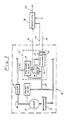
- FIG. 1 is a schematic drawing partially illustrating an aircraft hydraulic system 10 which embodies principles of the present invention. Hydraulic oil from a reservoir 12 is supplied via a pump 14 along a main supply conduit 16 and through a high-pressure filter 18.
- An air-in-oil sensor 20 receives the oil along a branch supply conduit 22 and returns the same to reservoir 12 via a branch vent conduit 24.
- the sensor 20 comprises a fluidic jet oscillator 26, a pressure divider 28, and a differential pressure transducer 30.
- the fluidic oscillator 26 is conventional in construction and is adapted to produce an output signal indicative of the density of the oil.
- the oscillator 26 is similar to apparatus described in the above-referenced patents, except that it is configured such that its two pressure transmission passages lead to opposite sides of a single piezoelectric transducer 32 rather than to separate transducers, and that it incorporates a thermistor 34 to monitor the temperature of the oil.
- the oscillator 26 in operation generates pressure waves that bear information indicative of the density of oil flowing therethrough.
- This information is communicated via the transducer 32 as an electrical frequency signal along a wire 36 to an external electronic processor 38.
- the differential pressure transducer 30 and thermistor 34 are elements of external circuit branches (indicated by lines 40, 42) connected to the processor 38 to provide differential pressure and temperature signals thereto.
- the processor 38 operatively responds to the frequency signals (as by communicating a change in status along an output line 44) only when the differential pressure signals are substantially in accord with a predetermined amplitude or frequency.
- the sensor 20 is further illustrated in FIG. 3 wherein the pressure divider 28 is shown in greater detail.
- the divider 28 is formed by a cylindrical housing 46 and a cylindrical spool 48.
- the housing 46 has an axially extending stepped bore 50 formed therein.
- the spool 48 has two larger-diameter threaded end portions 52, 54 separated by a smaller-diameter center portion 56. The end portions 52, 54 cooperate with the inner surface of the housing 46 to define two spaced flow restrictors.
- Three cross-bores extending from the outer surface of the housing 46 to the stepped bore 50 provide ports 58, 60, 62 through which the pressure divider 28 is in fluid communication with the branch vent conduit 24, an intermediate supply passage 64 leading to the supply port of the oscillator 26, and the branch supply conduit 22, respectively.
- the spool 48 is slidably disposed in a smaller-diameter portion of the stepped bore 50 as indicated so that the center portion 56 straddles the center port 60.
- a biasing spring 66 is rigidly secured to an adjustment screw 68 which is threadedly engaged with the housing 46. There is no preload on the spring 66. Thus, the spool 48 is urged against the spring 66 in response to the oil which is received at supply pressure through the high-pressure port 62.
- the spring 66 provides limited pressure regulation during operation of the sensor 20.
- a mounting plate 70 is adapted for securement to a manifold 71 of the hydraulic system 10 (FIG. 1). Rigidly secured to one side of the plate 70 is a laminar structure 72 comprising a plurality of thin laminae 74 which collectively form the oscillator 26, and a thick base laminate or block 76.
- the base laminate 76 is adapted to receive the pressure divider 28 by the provision of a first-bore 78, and to receive the thermistor 34 and differential pressure transducer 30 by the provision of a second bore 80.
- the differential pressure transducer 30, thermistor 34, and pressure divider 28 are inserted in the indicated bores 78, 80 and rigidly secured within the structure 72 by suitable means so that the sensor 20 is formed as an integral electrofluidic circuit element.
- the laminar structure 72 is adapted by the provision of channels (not shown) therein to provide for the required fluid communication indicated by FIGS. 1 and 2.
- both the laminar structure 72 and mounting plate 70 are adapted to provide for electrical communication from the differential pressure transducer 30 and thermistor 34 to a cylindrical boss 82 which is rigidly secured to the mounting plate 70 and is adapted for electrical connection to the processor 38 (FIG. 1).
- high-pressure oil is supplied from the branch supply conduit 22 to the high-pressure port 62 of the pressure divider 28.
- the oil pressure is stepped down by the pressure divider 28 and a portion of the oil flows at a lower pressure through the center port 60, along the supply passage 64, and to the supply port of the oscillator 26.
- the oscillator As the oil flows through the oscillator 26 to the vent passage 24, the oscillator generates a fluidic wavetrain having a frequency which depends on the density of the oil and on the difference in pressure between the supply passage 64 and the vent passage 24.
- the fluidic frequency signals are transduced to electrical frequency signals which are communicated to the processor 38.
- the differential pressure transducer 30 is fluidically connected across the oscillator 26 as indicated in FIG.
- the differential pressure transducer 30 provides amplitude or frequency signals which vary with the pressure difference between the supply and vent passages 64, 24. These signals are communicated to the processor 38, and the latter incorporates any of a variety of circuits which employ the signals received from the differential pressure transducer 30 to enable an operative control response only when the amplitude or frequency of the signal is in substantial accord with that associated with a predetermined differential pressure.
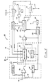
- FIG. 4 illustrates an exemplary gated sampling and control system 84.
- the system 84 is embodied in integrated circuit chips incorporating CMOS chip architecture and comprising a microprocessor 86, a memory register 88, and a current limiting line driver 90.
- a buffer amplifier 92 and accumulator register 94 form a differential counting register that receives frequency inputs 96, 98 from the fluidic oscillator 26 and a reference oscillator 100.
- the reference oscillator 100 is adapted to provide a predetermined reference frequency equivalent to that which is outputted by the fluidic oscillator 26 when the latter is operated at the predetermined differential pressure with zero percent air content in the oil.
- the differential frequencies are synchrogated into the accumulator register 94 on a continuous basis.
- the accumulator register 94 receives the differential frequency count, and receives the temperature signal from the thermistor 34.
- the latter signal is employed in the accumulator register 94 to bias the least significant bit and compensate for frequency shift due to temperature differences between the reference oscillator 100 and the fluidic oscillator 26.
- the synch- rogating circuit 102 is adapted to gate only those frequencies that accurately represent air content over the range of air content for which the system is designed.
- a time-out circuit 104 inhibits operation of the system 84 for a period of time prescribed by the user to enable the hydraulic system 10 (FIG. 1) to achieve stability of flow and air content. After that period, the system 84 is brought on line and the master clock 106 starts the microprocessor 86.
- An enable clock 108 is provided from the output of the master clock 106 via a frequency divider 110.
- the enable clock 108 sets a sampling period for the accumulator register 94 and resets the register at the end of the period.
- the data count of the accumulator register 94 is compared with a reference count from a reference register 112 by clocking both into a digital comparator 114.
- the output from the reference register 112 is a count limit associated with the frequency output from the fluidic oscillator 26 when the latter is operated at the predetermined differential pressure and with oil having a maximum percentage of air content as prescribed by the user.
- the output of the comparator 114 is an input to a set of control algorithms 116 programmed into the microprocessor 86.
- the digital output of a second comparator 118 is an input to the same set of algorithms.
- the inputs to the second comparator 118 are a voltage signal 120 received from the differential pressure transducer 30, and a reference voltage level 122 corresponding to the amplitude of the voltage signal 120 at the predetermined differential pressure.
- the output of the second comparator enables the microprocessor 86 to communicate a sampling command 124 to the enable clock 108.
- the control algorithms 116 incorporate a conventional seven-sample retry system to validate data which indicate excessive air content. When the accumulator register 94 and reference register 112 counts are sufficiently different to indicate by the output of the first comparator 114 that air content is excessive, seven sampling periods are used to validate the data.
- a command signal 126 is communicated to the line driver 90, which operatively responds to the command signal by communicating to a cockpit display or vehicle management system a signal 128 indicating a change in status.
- an additional algorithm is employed to detect a slowly changing air content that may cause the accumulator register 94 to contain a residual count over a seventy-unit sampling period. If seventy sampling periods register a consistently detectable count accumulation exceeding the count of the reference register 112, the microprocessor 86 communicates the command signal 126 to the line driver 90.
Abstract
Description
- The disclosure of U.S. Patent Nos. 4,508,127 Thurston and 4,930,357 Thurston et al is incorporated herein by reference thereto.
- This invention relates generally to liquid density measurement, and more specifically to liquid density measurement by electrofluidic means.
- In a fluidic oscillator the oscillation frequency of the fluid jet is directly dependent on the velocity of the fluid in the jet stream. If the differential pressure across the oscillator is held constant, then the density of the fluid is directly proportional to a constant divided by the square of the oscillation frequency. Such oscillators are disclosed in the above-referenced patents.
- When employed as density sensors these oscillators are combined with pressure regulators (such as the
regulator 42 illustrated in FIG. 2 of the '127 patent) to provide the constant differential pressure that is required. However, the pressure regulators are relatively massive, accounting for over ninety percent of the weight of the density meter. This creates problems in applications such as aircraft, for example, where weight and volume considerations may determine the choice made from among various density metering schemes. - An objective of this invention is to provide a process for electrofluidic liquid density measurement that accommodates the condition of varying differential pressure across the oscillator.
- A further objective is to provide relatively lightweight and low-volume apparatus adapted for use with the above-mentioned process.
- This invention achieves the forementioned objectives by enabling the use of a fluidic jet oscillator as a density meter absent the requirement for a conventional high-precision pressure regulator.
- In monitoring liquid density according to the invention, the liquid flows through a pressure divider and is forced under pressure through the fluidic oscillator. The oscillator responsively outputs a frequency signal that is indicative of the density of the liquid but is in error whenever the differential pressure across the oscillator varies from a predetermined value. The differential pressure is sensed by either two separate transducers or a single differential pressure transducer to produce a differential pressure signal.
- Although the differential pressure will vary due to the substitution of a pressure divider for a precision pressure regulator, the frequency signals can be treated as spurious when the differential frequency signal is not in substantial accord with the predetermined value. Therefore, by employing the differential pressure signals as enabling signals in a gated control system which operatively responds to the frequency signals only when the differential pressure signals are substantially in accord with the predetermined value, one can accurately monitor the density of a liquid by use of a fluidic oscillator in combination with a pressure divider and a differential pressure transducer. The use of a mere pressure divider in conjunction with a differential pressure transducer as a substitute for a high-precision pressure regulator permits a weight reduction in excess of ninety percent.
-
- FIG. 1 is a schematic illustration of an aircraft hydraulic system incorporating the invention.
- FIG. 2 is a perspective view of a contemplated electrofluidic circuit element adapted for use with the invention.
- FIG. 3 is a generally schematic and partially cross-sectional illustration of the apparatus shown in FIG. 2.
- FIG. 4 is a schematic illustration of a gated electronic control system adapted for use with the invention.
- FIG. 1 is a schematic drawing partially illustrating an aircraft
hydraulic system 10 which embodies principles of the present invention. Hydraulic oil from areservoir 12 is supplied via apump 14 along amain supply conduit 16 and through a high-pressure filter 18. - An air-in-
oil sensor 20 receives the oil along abranch supply conduit 22 and returns the same toreservoir 12 via abranch vent conduit 24. Thesensor 20 comprises afluidic jet oscillator 26, apressure divider 28, and adifferential pressure transducer 30. Thefluidic oscillator 26 is conventional in construction and is adapted to produce an output signal indicative of the density of the oil. Theoscillator 26 is similar to apparatus described in the above-referenced patents, except that it is configured such that its two pressure transmission passages lead to opposite sides of a singlepiezoelectric transducer 32 rather than to separate transducers, and that it incorporates athermistor 34 to monitor the temperature of the oil. Accordingly, theoscillator 26 in operation generates pressure waves that bear information indicative of the density of oil flowing therethrough. This information is communicated via thetransducer 32 as an electrical frequency signal along a wire 36 to an externalelectronic processor 38. Thedifferential pressure transducer 30 andthermistor 34 are elements of external circuit branches (indicated by lines 40, 42) connected to theprocessor 38 to provide differential pressure and temperature signals thereto. Theprocessor 38 operatively responds to the frequency signals (as by communicating a change in status along an output line 44) only when the differential pressure signals are substantially in accord with a predetermined amplitude or frequency. - The
sensor 20 is further illustrated in FIG. 3 wherein thepressure divider 28 is shown in greater detail. Thedivider 28 is formed by acylindrical housing 46 and acylindrical spool 48. Thehousing 46 has an axially extending steppedbore 50 formed therein. As indicated, thespool 48 has two larger-diameter threadedend portions diameter center portion 56. Theend portions housing 46 to define two spaced flow restrictors. Three cross-bores extending from the outer surface of thehousing 46 to thestepped bore 50 provideports pressure divider 28 is in fluid communication with thebranch vent conduit 24, anintermediate supply passage 64 leading to the supply port of theoscillator 26, and thebranch supply conduit 22, respectively. Thespool 48 is slidably disposed in a smaller-diameter portion of thestepped bore 50 as indicated so that thecenter portion 56 straddles thecenter port 60. Abiasing spring 66 is rigidly secured to anadjustment screw 68 which is threadedly engaged with thehousing 46. There is no preload on thespring 66. Thus, thespool 48 is urged against thespring 66 in response to the oil which is received at supply pressure through the high-pressure port 62. Thespring 66 provides limited pressure regulation during operation of thesensor 20. - As currently contemplated, the
sensor 20 is illustrated in FIG. 2. Amounting plate 70 is adapted for securement to amanifold 71 of the hydraulic system 10 (FIG. 1). Rigidly secured to one side of theplate 70 is a laminar structure 72 comprising a plurality ofthin laminae 74 which collectively form theoscillator 26, and a thick base laminate orblock 76. Thebase laminate 76 is adapted to receive thepressure divider 28 by the provision of a first-bore 78, and to receive thethermistor 34 anddifferential pressure transducer 30 by the provision of asecond bore 80. Thedifferential pressure transducer 30,thermistor 34, andpressure divider 28 are inserted in the indicatedbores sensor 20 is formed as an integral electrofluidic circuit element. Accordingly, the laminar structure 72 is adapted by the provision of channels (not shown) therein to provide for the required fluid communication indicated by FIGS. 1 and 2. Likewise, both the laminar structure 72 andmounting plate 70 are adapted to provide for electrical communication from thedifferential pressure transducer 30 andthermistor 34 to acylindrical boss 82 which is rigidly secured to themounting plate 70 and is adapted for electrical connection to the processor 38 (FIG. 1). - In operation, high-pressure oil is supplied from the
branch supply conduit 22 to the high-pressure port 62 of thepressure divider 28. The oil pressure is stepped down by thepressure divider 28 and a portion of the oil flows at a lower pressure through thecenter port 60, along thesupply passage 64, and to the supply port of theoscillator 26. As the oil flows through theoscillator 26 to thevent passage 24, the oscillator generates a fluidic wavetrain having a frequency which depends on the density of the oil and on the difference in pressure between thesupply passage 64 and thevent passage 24. The fluidic frequency signals are transduced to electrical frequency signals which are communicated to theprocessor 38. Thedifferential pressure transducer 30 is fluidically connected across theoscillator 26 as indicated in FIG. 3, and is electrically connected to theprocessor 38 so as to function as a differential-pressure-responsive oscillator. Accordingly, depending on the selected circuit configuration, thedifferential pressure transducer 30 provides amplitude or frequency signals which vary with the pressure difference between the supply andvent passages processor 38, and the latter incorporates any of a variety of circuits which employ the signals received from thedifferential pressure transducer 30 to enable an operative control response only when the amplitude or frequency of the signal is in substantial accord with that associated with a predetermined differential pressure. - FIG. 4 illustrates an exemplary gated sampling and
control system 84. Thesystem 84 is embodied in integrated circuit chips incorporating CMOS chip architecture and comprising amicroprocessor 86, amemory register 88, and a currentlimiting line driver 90. - A
buffer amplifier 92 andaccumulator register 94 form a differential counting register that receivesfrequency inputs fluidic oscillator 26 and areference oscillator 100. Thereference oscillator 100 is adapted to provide a predetermined reference frequency equivalent to that which is outputted by thefluidic oscillator 26 when the latter is operated at the predetermined differential pressure with zero percent air content in the oil. To provide initial noise immunity, the differential frequencies are synchrogated into theaccumulator register 94 on a continuous basis. Theaccumulator register 94 receives the differential frequency count, and receives the temperature signal from thethermistor 34. The latter signal is employed in theaccumulator register 94 to bias the least significant bit and compensate for frequency shift due to temperature differences between thereference oscillator 100 and thefluidic oscillator 26. The synch-rogating circuit 102 is adapted to gate only those frequencies that accurately represent air content over the range of air content for which the system is designed. To prevent anomalies during start-up, a time-out circuit 104 inhibits operation of thesystem 84 for a period of time prescribed by the user to enable the hydraulic system 10 (FIG. 1) to achieve stability of flow and air content. After that period, thesystem 84 is brought on line and themaster clock 106 starts themicroprocessor 86. An enableclock 108 is provided from the output of themaster clock 106 via afrequency divider 110. The enableclock 108 sets a sampling period for theaccumulator register 94 and resets the register at the end of the period. Prior to reset, the data count of theaccumulator register 94 is compared with a reference count from areference register 112 by clocking both into adigital comparator 114. The output from thereference register 112 is a count limit associated with the frequency output from thefluidic oscillator 26 when the latter is operated at the predetermined differential pressure and with oil having a maximum percentage of air content as prescribed by the user. The output of thecomparator 114 is an input to a set ofcontrol algorithms 116 programmed into themicroprocessor 86. The digital output of asecond comparator 118 is an input to the same set of algorithms. The inputs to thesecond comparator 118 are avoltage signal 120 received from thedifferential pressure transducer 30, and areference voltage level 122 corresponding to the amplitude of thevoltage signal 120 at the predetermined differential pressure. When theinput 120 is substantially in accord with theinput 122, the output of the second comparator enables themicroprocessor 86 to communicate asampling command 124 to the enableclock 108. Thecontrol algorithms 116 incorporate a conventional seven-sample retry system to validate data which indicate excessive air content. When theaccumulator register 94 and reference register 112 counts are sufficiently different to indicate by the output of thefirst comparator 114 that air content is excessive, seven sampling periods are used to validate the data. If any of the seven sampling periods does not yield a consistent output from thecomparator 114, the data are rejected as invalid. If all seven sampling periods show consistency in the output, acommand signal 126 is communicated to theline driver 90, which operatively responds to the command signal by communicating to a cockpit display or vehicle management system asignal 128 indicating a change in status. Preferably, an additional algorithm is employed to detect a slowly changing air content that may cause theaccumulator register 94 to contain a residual count over a seventy-unit sampling period. If seventy sampling periods register a consistently detectable count accumulation exceeding the count of thereference register 112, themicroprocessor 86 communicates thecommand signal 126 to theline driver 90. - The invention should be construed in the broadest manner consistent with the following claims and their equivalents.
Claims (3)
Applications Claiming Priority (2)
| Application Number | Priority Date | Filing Date | Title |
|---|---|---|---|
| US59794590A | 1990-10-15 | 1990-10-15 | |
| US597945 | 1990-10-15 |
Publications (2)
| Publication Number | Publication Date |
|---|---|
| EP0481264A1 true EP0481264A1 (en) | 1992-04-22 |
| EP0481264B1 EP0481264B1 (en) | 1996-11-20 |
Family
ID=24393591
Family Applications (1)
| Application Number | Title | Priority Date | Filing Date |
|---|---|---|---|
| EP19910116418 Expired - Lifetime EP0481264B1 (en) | 1990-10-15 | 1991-09-26 | Method and apparatus for measuring the density of a liquid |
Country Status (2)
| Country | Link |
|---|---|
| EP (1) | EP0481264B1 (en) |
| DE (1) | DE69123218T2 (en) |
Families Citing this family (1)
| Publication number | Priority date | Publication date | Assignee | Title |
|---|---|---|---|---|
| CN101936865B (en) * | 2010-07-21 | 2011-10-26 | 北京航空航天大学 | Density measuring method suitable for single-phase flow fluid and measuring device thereof |
Citations (4)
| Publication number | Priority date | Publication date | Assignee | Title |
|---|---|---|---|---|
| US4175423A (en) * | 1978-05-01 | 1979-11-27 | Sun Oil Company (Delaware) | Apparatus for determining the pulse repetition rate of a fluidic oscillator through which a test gas is flowing |
| EP0117150A2 (en) * | 1983-02-22 | 1984-08-29 | Uop Inc. | Monitor for detemining an unknown property of a gas or vapor sample |
| US4508127A (en) * | 1983-03-30 | 1985-04-02 | The Garrett Corporation | Fuel mass flow measurement and control system |
| US4644781A (en) * | 1984-12-07 | 1987-02-24 | The United States Of America As Represented By The Secretary Of The Army | Fluid property measuring device |
-
1991
- 1991-09-26 EP EP19910116418 patent/EP0481264B1/en not_active Expired - Lifetime
- 1991-09-26 DE DE1991623218 patent/DE69123218T2/en not_active Expired - Fee Related
Patent Citations (4)
| Publication number | Priority date | Publication date | Assignee | Title |
|---|---|---|---|---|
| US4175423A (en) * | 1978-05-01 | 1979-11-27 | Sun Oil Company (Delaware) | Apparatus for determining the pulse repetition rate of a fluidic oscillator through which a test gas is flowing |
| EP0117150A2 (en) * | 1983-02-22 | 1984-08-29 | Uop Inc. | Monitor for detemining an unknown property of a gas or vapor sample |
| US4508127A (en) * | 1983-03-30 | 1985-04-02 | The Garrett Corporation | Fuel mass flow measurement and control system |
| US4644781A (en) * | 1984-12-07 | 1987-02-24 | The United States Of America As Represented By The Secretary Of The Army | Fluid property measuring device |
Also Published As
| Publication number | Publication date |
|---|---|
| DE69123218T2 (en) | 1997-03-27 |
| EP0481264B1 (en) | 1996-11-20 |
| DE69123218D1 (en) | 1997-01-02 |
Similar Documents
| Publication | Publication Date | Title |
|---|---|---|
| US5237853A (en) | Method and apparatus for measuring the density of a liquid | |
| US4550592A (en) | Pneumatic gauging circuit | |
| EP0122100B1 (en) | Fluid density and mass flow measurement | |
| EP0305134B1 (en) | Fluid metering system | |
| US6938496B2 (en) | Vortex flow pickup | |
| EP0812414B1 (en) | Pressure transmitter with remote seal diaphragm and correction for temperature and vertical position ( also diaphragm stiffness ) | |
| US4463601A (en) | Method and apparatus for measuring mass airflow | |
| US4142401A (en) | Gage | |
| US4486303A (en) | Ultrafiltration in hemodialysis | |
| US8474322B1 (en) | Eccentric load sensing device used to sense differential pressures | |
| KR20020063592A (en) | Thermal flowmeter with fluid discriminant function | |
| EP0152451A1 (en) | Planar-measuring vortex-shedding mass flowmeter. | |
| FR2685766B1 (en) | METHOD AND DEVICE FOR MEASURING GAS FLOW. | |
| GB2026704A (en) | Device for Measuring Fluid Flow in Tubing | |
| EP0670476B1 (en) | A fluid sensor | |
| AU4944593A (en) | Flow meter | |
| EP0079942B1 (en) | Flow splitting device for fluid flow meter | |
| EP0481264B1 (en) | Method and apparatus for measuring the density of a liquid | |
| US6917886B2 (en) | Microflow based differential pressure sensor | |
| US4809499A (en) | Densimeter | |
| CA2459564C (en) | Vortex flow pickup | |
| US4709575A (en) | Fluidic oxygen sensor monitor | |
| WO1992020989A1 (en) | Film thickness measuring capacitive sensors | |
| GB1574702A (en) | Fluid flow measuring assembly | |
| JPS6189519A (en) | Sensitivity adjustable flow rate sensor |
Legal Events
| Date | Code | Title | Description |
|---|---|---|---|
| PUAI | Public reference made under article 153(3) epc to a published international application that has entered the european phase |
Free format text: ORIGINAL CODE: 0009012 |
|
| AK | Designated contracting states |
Kind code of ref document: A1 Designated state(s): DE FR GB IT SE |
|
| 17P | Request for examination filed |
Effective date: 19921006 |
|
| RAP1 | Party data changed (applicant data changed or rights of an application transferred) |
Owner name: ALLIEDSIGNAL INC. |
|
| 17Q | First examination report despatched |
Effective date: 19951124 |
|
| GRAH | Despatch of communication of intention to grant a patent |
Free format text: ORIGINAL CODE: EPIDOS IGRA |
|
| GRAH | Despatch of communication of intention to grant a patent |
Free format text: ORIGINAL CODE: EPIDOS IGRA |
|
| GRAA | (expected) grant |
Free format text: ORIGINAL CODE: 0009210 |
|
| AK | Designated contracting states |
Kind code of ref document: B1 Designated state(s): DE FR GB IT SE |
|
| ITF | It: translation for a ep patent filed |
Owner name: JACOBACCI & PERANI S.P.A. |
|
| ET | Fr: translation filed | ||
| REF | Corresponds to: |
Ref document number: 69123218 Country of ref document: DE Date of ref document: 19970102 |
|
| PGFP | Annual fee paid to national office [announced via postgrant information from national office to epo] |
Ref country code: GB Payment date: 19970804 Year of fee payment: 7 |
|
| PGFP | Annual fee paid to national office [announced via postgrant information from national office to epo] |
Ref country code: SE Payment date: 19970818 Year of fee payment: 7 |
|
| PGFP | Annual fee paid to national office [announced via postgrant information from national office to epo] |
Ref country code: FR Payment date: 19970905 Year of fee payment: 7 |
|
| PLBE | No opposition filed within time limit |
Free format text: ORIGINAL CODE: 0009261 |
|
| STAA | Information on the status of an ep patent application or granted ep patent |
Free format text: STATUS: NO OPPOSITION FILED WITHIN TIME LIMIT |
|
| PGFP | Annual fee paid to national office [announced via postgrant information from national office to epo] |
Ref country code: DE Payment date: 19970930 Year of fee payment: 7 |
|
| 26N | No opposition filed | ||
| PG25 | Lapsed in a contracting state [announced via postgrant information from national office to epo] |
Ref country code: GB Free format text: LAPSE BECAUSE OF NON-PAYMENT OF DUE FEES Effective date: 19980926 |
|
| PG25 | Lapsed in a contracting state [announced via postgrant information from national office to epo] |
Ref country code: SE Free format text: LAPSE BECAUSE OF NON-PAYMENT OF DUE FEES Effective date: 19980927 |
|
| GBPC | Gb: european patent ceased through non-payment of renewal fee |
Effective date: 19980926 |
|
| EUG | Se: european patent has lapsed |
Ref document number: 91116418.4 |
|
| PG25 | Lapsed in a contracting state [announced via postgrant information from national office to epo] |
Ref country code: FR Free format text: LAPSE BECAUSE OF NON-PAYMENT OF DUE FEES Effective date: 19990531 |
|
| PG25 | Lapsed in a contracting state [announced via postgrant information from national office to epo] |
Ref country code: DE Free format text: LAPSE BECAUSE OF NON-PAYMENT OF DUE FEES Effective date: 19990701 |
|
| REG | Reference to a national code |
Ref country code: FR Ref legal event code: ST |
|
| PG25 | Lapsed in a contracting state [announced via postgrant information from national office to epo] |
Ref country code: IT Free format text: LAPSE BECAUSE OF NON-PAYMENT OF DUE FEES;WARNING: LAPSES OF ITALIAN PATENTS WITH EFFECTIVE DATE BEFORE 2007 MAY HAVE OCCURRED AT ANY TIME BEFORE 2007. THE CORRECT EFFECTIVE DATE MAY BE DIFFERENT FROM THE ONE RECORDED. Effective date: 20050926 |
|
| P01 | Opt-out of the competence of the unified patent court (upc) registered |
Effective date: 20230525 |