EP0117150A2 - Monitor for detemining an unknown property of a gas or vapor sample - Google Patents
Monitor for detemining an unknown property of a gas or vapor sample Download PDFInfo
- Publication number
- EP0117150A2 EP0117150A2 EP84301101A EP84301101A EP0117150A2 EP 0117150 A2 EP0117150 A2 EP 0117150A2 EP 84301101 A EP84301101 A EP 84301101A EP 84301101 A EP84301101 A EP 84301101A EP 0117150 A2 EP0117150 A2 EP 0117150A2
- Authority
- EP
- European Patent Office
- Prior art keywords
- sample
- oscillator
- pressure
- gas
- temperature
- Prior art date
- Legal status (The legal status is an assumption and is not a legal conclusion. Google has not performed a legal analysis and makes no representation as to the accuracy of the status listed.)
- Withdrawn
Links
Images


Classifications
-
- F—MECHANICAL ENGINEERING; LIGHTING; HEATING; WEAPONS; BLASTING
- F15—FLUID-PRESSURE ACTUATORS; HYDRAULICS OR PNEUMATICS IN GENERAL
- F15C—FLUID-CIRCUIT ELEMENTS PREDOMINANTLY USED FOR COMPUTING OR CONTROL PURPOSES
- F15C1/00—Circuit elements having no moving parts
- F15C1/005—Circuit elements having no moving parts for measurement techniques, e.g. measuring from a distance; for detection devices, e.g. for presence detection; for sorting measured properties (testing); for gyrometers; for analysis; for chromatography
-
- F—MECHANICAL ENGINEERING; LIGHTING; HEATING; WEAPONS; BLASTING
- F15—FLUID-PRESSURE ACTUATORS; HYDRAULICS OR PNEUMATICS IN GENERAL
- F15C—FLUID-CIRCUIT ELEMENTS PREDOMINANTLY USED FOR COMPUTING OR CONTROL PURPOSES
- F15C1/00—Circuit elements having no moving parts
- F15C1/22—Oscillators
Definitions
- This invention relates to the determination of the . characteristics of substances in gaseous form, and more specifically to determination of heating value, or heat of combustion, density, and humidity or moisture content of a gas or vaporized liquid.
- Fuels in liquid or gaseous form are burned to produce heat for a plethora of applications. These fuels may vary in composition from primarily single carbon hydrocarbons to hydrocarbons having many carbon atoms arranged in branched chain or ring structures or may be mixtures of many hydrocarbons. Often a fuel contains compounds which are inert with respect to normal combustion. It is useful to know the heating value of a fuel, that is, the amount of heat which a certain quantity of a fuel will produce when it is burned under a certain set of conditions. While the heating values of most pure substances capable of being used as fuels are readily available in the literature, that a myriad number of mixtures of compounds are used as fuels results in a continuing need for making heating value determinations. Apparatus and methods for determining heating values are used both in laboratories and in industrial operations outside the laboratory. It is often desirable to monitor heating value of a flowing stream on a continuous basis. Following are several exemplary applications for heating value monitoring.
- the payment made for the gas will probably be based on its heating value as well as the quantity burned.
- Average heating value may be determined by periodic laboratory analysis or the heating value may be continuously measured as the gas enters the user's plant.
- heating values of the by-product gas must be determined, before its actual use begins, for reasons other than pricing. Design and control of the burner, furnace, and other equipment involved in handling and burning the gas depends in part on the range of heating values which can be expected. Heating value of a by-product gas would normally vary over a fairly large range, compared to natural gases, and the average heating value would be different from that of natural gases.
- temperature and/or furnace atmosphere must be maintained in a relatively narrow range in order to assure product-quality. Changes in heating value of the fuel supplied to the furnace may necessitate corrective action to avoid an excursion from the acceptable range.
- An increase in heating value of a fuel indicates that more oxygen is required to combine with it.
- a furnace atmosphere is required to be rich in oxygen
- an increase in rate of oxygen depletion in the furnace caused by an increased heating value may create quality problems.
- the solution is often to increase oxygen flow as soon as an increase in heating value is detected by a heating value monitor and thereby avoid significant depletion.
- Fuel savings can be realized by using a heating value monitor in a combustion zone control system.
- the amount of air supplied to the combustion zone can be adjusted by reference to the heating value monitor so that the excess air quantity is small, thus saving fuel used for heating unneeded air and so that use of extra fuel as a result of incomplete combustion is avoided.
- U.S. Patent 4,337,654 a fixed amount of gas is burned with a measured quantity of air and hydrogen or oxygen supplied by an electrolytic cell. The amount of hydrogen or oxygen added is controlled by an oxygen sensor and related to the heating value of the gas burned.
- U.S. Patent 4,355,533 describes a method of determining heating value where information developed by use of a gas chromatograph is correlated with heating value.
- U.S. Patent Nos. 4,329,873 and 4,329,874 describe another calorimeter in which gas is oxidized.
- a typical application is a mass flow meter, where volumetric flow rate is combined with the density of the flowing stream to produce mass flow rate.
- One seeking to measure density, particularly on a continuous on-line basis, has a limited choice of apparatus.
- One commercially available density meter utilizes an oscillating element in the fluid whose density is measured. Oscillation is caused by an electromagnetic field. The frequency of oscillation depends on the density of the fluid.
- the sensing element is contained in a housing having one-inch flanges for installation in a pipeline.
- a standard reference, Process Instruments and Controls Handbook, 2nd ed., 1974, edited by Considine lists only three techniques for measuring density, none of which are well suited for use outside the laboratory. The listed methods (p. 6-152) are as follows.
- a buoyancy gas balance consists of a vessel containing a displacer mounted on a balance beam and with a manometer connected to it. Displacer balance is established with the vessel filled with air and then filled with gas, the pressure required to do so being noted from the manometer in both cases. The pressure ratio is the density of the gas relative to air.
- a viscous drag density instrument an air stream and a stream of the gas under test are passed through separate identical chambers, each containing a rotating impeller.
- the two streams are acted upon by the rotating impellers and in turn each acts upon a non-rotating impeller mounted in the opposite end of the chamber.
- the non-rotating impellers are coupled together by a linkage and measure the relative drag shown by the tendency of the impellers to rotate, which is a function of relative density.
- This invention also relates to determination of humidity, or moisture content, of a gas or vaporized liquid. It is primarily useful for analyzing gases where the moisture content is large and there is a small difference between the molecular weight of water and the average molecular weight of the other components of the gas or where there is a large difference between the molecular weight of water and the average molecular weight of the other components.
- the invention comprises (a) a fluidic oscillator; (b) means for establishing flow of the sample through said oscillator ' (c) means for measuring or controlling the pressure at which the sample passes through said oscillator and for providing a signal representative of the pressure when pressure is not controlled in a previously established range; (d) means for measuring the temperature of the sample at said oscillator and for providing a signal representative of the temperature; (e) means for measuring the frequency of oscillation at said oscillator and for providing a signal representative of the frequency; (f) computing means for reading said signals and for calculating the unknown property of the sample using equations and data stored in said computing means and data supplied by said means for providing a pressure signal when pressure is not controlled in a previously established range; and, (g) means for communicating information contained in said computing means.
- a device known as a fluidic oscillator is used in this invention. This is one of a class of devices which are utilized in the field of fluidics.
- a fluidic oscillator may have any of a number of different configurations in addition to that depicted in FIGURE 1.
- the publications mentioned under the heading "Statement of Art" describe fluidic oscillators and their governing principles in detail and therefore it is unnecessary to present herein more than the following simple description.
- a fluidic oscillator may be described as a set of passageways, in a solid block of material, which are configured in a particular manner. If the passageways are centered in the block and the block is cut in half in the appropriate place, a view of the cut surface would appear as the schematic diagram of FIGURE 1.
- a gas stream enters the inlet, flows through nozzle 109, and "attaches" itself to one of two stream attachment walls 105 and 106 in accordance with the principle known as the Coanda effect. Gas flows through either exit passage 107 or exit passage 108, depending on whether the stream is attached to wall 105 or wall 106.
- Exit passages 107 and 108 can be considered as extending to the outside of the block of material in a direction perpendicular to the plane in which the other passages lie.
- a pressure pulse is produced that passes through delay line 104.
- the pressure pulse impinges on the gas stream at the outlet of nozzle 109, forcing it to "attach" to wall 106 and flow through exit passage 108.
- a pulse passing through delay line 103 then causes the stream to switch back to wall 105. It is in this manner that an oscillation is established.
- the frequency of the oscillation is a function of the pressure propagation time through the delay line and time lag involved in the stream switching from one attachment wall to the other.
- the pressure propagation time is a function of the characteristics of the gas, as shown in the above mentioned publications and also by the equations which are presented herein.
- the frequency of oscillation can be sensed by a pressure sensor or microphone located in one of the passages, such as shown by sensing port 102.
- a differential sensing device connected to both passages can also be used.
- Sensing port 101 is shown to indicate one potential location for a temperature sensor.
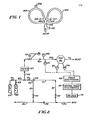
- FIG. 2 gas is flowing through pipeline 50.
- a sample flow loop 51 is formed by means of conduit, such as 3/4-inch (19 mm) diameter pipe, connected to pipeline 50 upstream and downstream of pressure drop element 53.
- the purpose of pressure drop element 53 is to cause a loss of pressure in pipeline 50 which is the same as the pressure drop in flow loop 51 when a sufficient amount of gas is passing through flow loop 51.
- Gas flow through flow loop 51 is sufficient when gas composition at sample point 54 is substantially the same as that in pipeline 50 at any given instant.
- Normally pressure drop element 53 is a device present in the pipeline for a primary purpose unrelated to taking a sample, for example, a control valve.
- a sufficient length of pipeline 50 can serve as pressure drop element 53 or an orifice plate can be installed in pipeline 50 to serve the purpose.
- Valves 52 are used to isolate flow loop 51 from pipeline 50.
- pressure and temperature of the gas flowing in pipeline 50 are provided by pressure transmitter 75 and temperature transmitter 76. These are located close to pipeline 50, so that differences in pressure and temperature between their locations and pipeline 50 are not significant. Pipeline 50 is covered with thermal insulation of a type commonly used on pipelines. The location shown in Figure 3 has the advantage of allowing the density monitor to be a self-contained package. However, if the pressure and temperature differences are significant, transmitters 75 and 76 can be located directly on pipeline 50. The measured pressure and temperature are referred to herein as T 1 and P l .
- Figure 4 represents one alternative embodiment of the present invention wherein it is desired to determine the moisture content of a gas sample.
- Flow of a gas sample is provided in parallel through first fluidic oscillator 56 and second fluidic oscillator 78 with means for adjusting the water content of a portion of the sample before it passes through the second oscillator 78.
- sample lines 55 carry samples of gas from sample points 54 to fluidic oscillators 56.
- Sample line 77 branches off to supply a sample of gas to fluidic oscillator 78 in the embodiment of Figure 4.
- Filters 57 are provided to remove particles which might be present in the sample, so that the narrow passages of fluidic oscillators 56 and 78 or other flow paths will not become plugged.
- Pressure regulators 58 of the self-contained type with an integral gauge, are provided so that gas flowing through oscillators 56 and that flowing through oscillator 78 is at a substantially constant pressure. The frequency of oscillation at the oscillators may vary with pressure, depending on the particular oscillators used and the actual pressure at the oscillators.
- Orifices 60 are provided for the purpose, in conjunction with pressure regulators 58, of maintaining a constant flow of gas through each oscillator.
- Pressure gauges 59 indicate the pressures downstream of orifices 60. Normally it is not necessary to install orifices 60, as the sample lines or the inlet ports of the oscillators serve the same purpose.
- Conduits 71 ( Figures 2, 3, 4) and 79 ( Figure 4) carry the samples away from oscillators 56 ( Figure 2, 3, 4) and 78 ( Figure 4), to the atmosphere in a location where discharge of the gas will cause no harm or to a process vessel where it can be utilized. However, the quantity of gas is sufficiently small that it may not be economical to do more than discharge it to the atmosphere.
- Pressure transmitters 61 are switch devices which provide signals for actuation of alarms if the pressures do not remain in previously established ranges. Thus communication that inaccurate results may be obtained is accomplished.
- d' ryer 80 is provided to remove substantially all water from the gas which passes through oscillator 78. There are many commercially available devices to accomplish this. A typical device contains two beds of a desiccant material so that gas to be desiccated passes through one bed while the other bed is being regenerated by applied heat.
- Obtaining a representative sample stream from a pipeline, providing it to the inlet port of a fluidic oscillator, removing it from the outlet port of the oscillator, and maintaining a substantially constant pressure drop across the oscillator can be accomplished by a variety of different means and methods for each given set of conditions, such as desired flow rate through the oscillator and pipeline pressure. These means and methods, which can be applied as alternatives to those shown in Figures 2, 3 and 4, are well known to those skilled in the art.
- a fluidic oscillator can be designed and fabricated upon reference to the literature, such as that mentioned under the heading "Statement of Art" or may be purchased.
- an oscillator supplied by Garrett Pneumatic Systems Division of Phoenix, Arizona was used.
- This oscillator is of a different configuration than that shown in FIGURE 1 in that the "loops" formed by delay lines 103 and 104 are open such that the "loops” define cavities and in that there is only one exit passage. Drawings of this configuration can be found in the cited references.
- the flow rate through this oscillator when testing natural gas is approximately 250 cm 3 /min when upstream pressure is approximately 20 psig (a gauge pressure of 1.4 kg/cm 2 ) and the oscillator is vented directly to atmosphere.
- a flow rate range of 200 to 500 cm 3 /min is considered to be reasonable for commercial use and sufficient to provide acceptable humidity results.
- Temperature transmitters 67 ( Figures 2, 3, 4) and 81 ( Figure 4) provide the temperature of the gas at each oscillator. Any of the well known means of sensing temperature may be used, such as a thermister, thermocouple, or solid state semiconductor sensor. The sensor may be located in a passage of the oscillator, such as shown in FIGURE 1 (sensing port 101), or in the sample line or conduit adjacent to the oscillator. Microphones 66 ( Figures 2, 3, 4) and 82 ( Figure 4) sense the frequency of oscillation at each oscillator. A microphone is located in a position to sense when the gas stream attaches itself to one of the walls, such as the position shown in FIGURE 1 (sensing port 102).
- sensors which can be used, for example, a piezoceramic transducer, in which pressure induces a voltage change, or a piezo-resistance transducer, in which pressure induces a resistance change.
- a piezoceramic transducer in which pressure induces a voltage change
- a piezo-resistance transducer in which pressure induces a resistance change.
- Used in test work applicable to this invention was a Series EA 1934 microphone supplied by Knowles Electronics of Franklin Park, 111.
- Signals from microphones 66 and 82, temperature transmitters 67 and 81, and pressure transmitters 61 are processed by equipment denoted field electronics 68 and control room electronics 69.
- Field electronics are located adjacent to the oscillators while control room electronics are in a central control room some distance away from the oscillators. This equipment processes the signals to obtain humidities of the gas and performs other functions which will be described herein.
- Display unit 70 receives signals from control room electronics 69 and communicates humidities of the sample gas and other information in human-readable form. It may be, for example, a liquid crystal display. The information may be communicated to other equipment, such as a strip chart recorder for making a permanent record or a computer for further manipulation.
- Two containers of calibration gas, 64 and 65 are provided to check that the monitor is operating properly. Normally one of the calibration gases has properties in the lower part of the range of values expected of the gas flowing in pipeline 50 and one has properties in the higher part of that range.
- the monitor is placed in the appropriate calibration mode by means of one of input switches 18 ( Figure 5). By mani- potating valves 63, 72 and 73, the calibration gases are allowed to flow, in turn, through calibration conduit 62 and sample line 55 to oscillator 56.
- the monitor may be arranged so that properties of the calibration gases are displayed and a human technician must, if necessary, adjust the monitor to the known calibration gas property values, or may be arranged so that the monitor is capable of adjusting itself.
- the monitor could re-calculate the values of constants stored in it which are used in calculating sample humidities or densities or heating values. Periodic calibration must be accomplished to check for malfunctions and changes which might take place in the apparatus such as electronic drift, corrosion, and substances accumulating in the apparatus.
- the calibration gas densities calculated by the monitor must be adjusted to a pressure and temperature at which the calibration gas densities are known. For example, if pressure transmitter 61 measures a pressure of 20 psig (140 kPa gauge) and temperature transmitter 67 measures a temperature of 30°F (-1.1°C) when calibration gas from container 64 is flowing and the density of container 64 gas is known to be 0.0448 lb/ft 3 (0.718 kg/m3) at 0°C and 1 atmosphere (101 kPa gauge), the density communicated by the monitor must be at 0°C and 1.0 atmosphere (101 kPa).
- the monitor is not operating properly. Adjustment of a density value from one pressure and temperature to another is easily accomplished by means of the equation of state presented herein.
- the monitor may be arranged so that densities of the calibration gases are displayed and a human technician must, if necessary, adjust the monitor to the known calibration gas densities, or may be arranged so that the monitor is capable of adjusting itself. For example, as was done in the prototype device, the monitor could re-calculate the values of constants stored in it which are used in calculating sample densities.
- Partial calibrations, or operation checks can be accomplished in a number of different ways. Use of a calibration gas can be combined with operation checks accomplished electronically. A totally electronic operational check can be made. For example, means for generating appropriate oscillating tones can be provided at microphones 66 ( Figures 2,3,4) and 82 ( Figure 4) so that new values of Kland K 2 can be calculated. Of course, this procedure checks only the electronics and not the oscillator. In another simple check, tuning forks are used to generate tones at microphones 66 and 82 and the synthetic "value" resulting from the tone inputs is compared to the expected proper value in computing means. Operational checks can be performed by switchingflow form one oscillator to the other in the embodiment of Figure 4. Temperature changes can be used to perform operational checks.
- heating means such as electrical resistance coils
- FIGURE 5 shows one such design in simplified form.
- Line 19 indicates which items are located in the field and which are located in the control room.
- FigureS is drawn for the cases in which only one oscillator is used. It can easily be seen that certain items would need to be duplicated so data relating to two oscillators can be provided to the computing means.
- oscillator 78 Figure 4
- a signal from microphone 66 is provided to amplifier 1, passed through filter 2, and converted to a -square wave pulse in square wave shaper 3.
- the output of square wave shaper 3 is provided to counter 6 by means of transmitter 4 and receiver 5.
- Counter 6 counts the number of cycles occurring in oscillator 56 in a unit of time, thus generating frequency information.
- the signals from pressure transmitter 61 and temperature transmitter 67 are selected one at a time by analog switching device 7 and sent sequentially to analog-to-digital converter 8, where they are converted to digital form.
- Serial input/output device 9 converts the output of analog-to-digital converter 8 to a serial pulse train, which is provided by means of transmitter 10 and receiver 11 to serial input/output device 12, located in the control room.
- Memory device 15 a random access memory chip (RAM), is used to store the variables.
- a program for control of the electronics devices and performing computations is stored in memory device 14, a programmable read-only memory chip (PROM). Constants needed for the computation are stored in memory device 16, an electronically erasable programmable read-only memory chip (EEPROM).
- Central processing unit 13 performs the necessary computations and provide output signals to display unit 70 ( Figures 2, 3,4).
- Input switches 18 are used to provide human input to the electronic components. These are rotary click-stop switches which can be set to any digit from 0 to 9. One of the switches is the mode switch and the others are used to enter numerical values. The position of the mode switch "instructs" the apparatus what to do.
- the apparatus displays the humidity of a sample.
- the mode switch When the mode switch is placed in the "constant load” position, numerical values of constants can be manually set on the other switches and loaded into the system by depressing a button. Another position of the mode switch allows values of variables to be displayed in sequence on display 70. When it is desired to calibrate the apparatus, still other positions are used. Additional positions are used as required.
- Parallel input/output device 17 provides a means of transmitting information from input switches 18 and also controlling counter 6. It will be clear to one skilled in the art that certain of the electronics devices may be collectively referred to as a computer or computing means or may be contained within a computer or computing means.
- the quantity 6 can be provided as a constant stored in computer memory or can be calculated by means of a correlation, such as the eauation where K 3 , K 4 , K 5 and K 6 are constants.
- the computer is programmed to solve these equations for each oscillator, using values of F and T provided as described above, and values of constants which exist in computer memory. It can be readily seen that these molecular weights can be used to obtain the moisture content of the sample by means of the equations where
- the computer is programmed to solve these equations to obtain H, using values of F and T provided as described above, and values of constants which exist in computer memory.
- the density of the gas can be calculated by use of the equation where
- the computer is programmed to solve these equations to obtain D, using values of F, T, T,, and P 1 provided as described above, and values of constants which exist in computer memory.
- the equation for G used in the prototype unit was developed by a standard curve-fitting method using values of G available in the literature for gases such as methane, ethane, etc. As can be appreciated by those skilled in the art, there are other ways to develop and express G and to store it in the computer. The most appropriate method is dependent on the particular application.
- the compressibility factor, Z from the equation of state to calculate density, is a measure of the deviation of the sample gas from ideality and is added to the expression commonly known as the ideal gas law in order to make the ideal gas law applicable to real gases. Since compressibility factors are covered by a vast quantity of literature which includes a number of different methods of computing them, there is no need to explain the basic theory herein. For further information and references to the literature, refer to Basic Principles and Calculations in Chemical Engineering, 2nd edition, 1967, Prentice-Hall, Inc., by Himmelblau, p. 149 and following. Also useful are Chemical Process Principles, 2nd edition, 1954, John Wiley & Sons, by Hougen et al, p. 87, and Perry's Chemical Engineers' Handbook, 4th edition, McGraw-Hill, p. 4-49.
- Z is calculated by means of the equation where for M between 16 and 21.75, or for M between 21.76 and 27.55, and
- H may be provided in metric units by appropriately programming the computer or the Wobbe Index of the sample gas may be presented.
- the sample gas may contain compounds which are non-combustible.
- concentrations and molecular weights of these compounds must be provided to the computer in order to produce an accurate heating value. This may be done by means of an analyzer through which the sample gas is passed and which is arranged to automatically provide appropriate signals to the computer.
- analyzer apparatus such as a gas chromatograph.
- average values of concentrations and molecular weights of the non-combustible components may be manually entered into the computer.
- natural gas often contains carbon dioxide and nitrogen and their concentrations do not vary greatly from hour to hour. It will often be satisfactory to analyze for these once a day and enter values by use of the input switches mentioned above.
- H concentrations and molecular weights of combustible constituents in the same manner as non-combustible constituents in order to improve accuracy.
- the equation used to calculate H can easily be modified for these applications.
- An example is the measurement of heating value of off-gas from a hydrogen-producing hydrogen recycle process, such as catalytic reforming or dehydrogenation.
- U.S. Patent No. 3,974,064 (Bajek et al.) may be consulted.
- the off-gas is often used in whole or part as a fuel. It is comprised of both hydrogen and various hydrocarbon compounds.
- a heating value monitor in control of a combustion zone may be highly desirable or necessary to achieve acceptable control.
- a typical control arrangement is to measure furnace temperature and adjust fuel flow to maintain it constant. When the amount of heat absorbed by the process increases, the temperature drops and more fuel is burned to increase temperature to the proper value. Also, changes in fuel heating value will cause furnace temperature changes for which the control system must compensate. Since the performance of a control system degrades as the number of factors for which it must compensate increases, it is desirable to eliminate fluctuations in temperature resulting from changes in fuel heating value. This can be accomplished by measuring fuel flow and heating value, establishing a signal representative of their product, and adjusting fuel flow by reference to this product.
- the product is representative of rate of heat flow to the process.
- the rate of heat flow is adjusted with reference to process temperature.
- a temperature controller receiving a signal representative of furnace temperature would supply the set point, in cascade fashion, to a controller which receives a signal representative of the heat content of the fuel and adjusts the fuel flow control valve.
- a heating value monitor may be applied to improve fuel economy.
- Combustion air flow rate is normally established by measuring fuel flow and combining a signal representative of fuel flow with a previously established ratio value to obtain a signal used to adjust air rate.
- This control method is incapable of responding to changes in fuel heating value, so normal practice is to set up the system so that excess air is supplied to the combustion zone. Excess air is that quantity of air which is not needed to combine with the fuel. It is desirable to keep excess air at a minimum as the amount of fuel used to heat it represents a total loss. As the fuel heating value increases, more combustion air is required. If insufficient combustion air is supplied, fuel is wasted as a result of incomplete combustion.
- a signal representative of fuel gas heating value can be used to adjust air flow rate, usually by means of adjusting the ratio value, so that the excess air quantity is small, thus saving fuel for heating unneeded air and avoiding use of extra fuel.
- FIGURE 2 shows an embodiment of the invention where a continuous flow of sample through the oscillator is established in order to obtain a continuous heating value for gas flowing in a process pipeline.
- An embodiment of the invention for use in a laboratory would not require the flow loop shown in FIGURE 2.
- Sample can be collected in an evacuated pressure-resistant container, commonly called a sample bomb, which is then connected to sample line 55.
- a means for vaporizing the liquids is required. This can be accomplished, for example, by use of electric resistance heating elements surrounding a portion of conduit through which the sample passes.
- gas is frequently used herein; it should be understood to include vapors resulting from fuels which are initially in liquid form. For example, it may be desired to determine the heating value of a sample of No. 2 fuel oil, which is liquid at normal ambient temperatures.
- the sample loop shown in Figure 3 omitted.
- Sample is collected-in an evacuated pressure-resistant container, which is then connected to sample line 55, either upstream or downstream of filter 57.
- the density communicated by the apparatus is that at the temperature and the pressure measured by pressure transmitter 61 and temperature transmitter 67. There is no need to divide the electronics into two packages at two different locations.
- This embodiment might be used in a laboratory. It might be desired to add to this embodiment the feature that the apparatus is capable of calculating a density value for sample gas at pressures and temperatures different from those measured by transmitters 61 and 67 and which are provided to the apparatus as follows.
- a temperature and a pressure can be manually entered into the apparatus by means such as input switches 18 or they can be provided by apparatus which measures temperature and pressure at some point of interest and transmits appropriate signals to the computing means of the invention.
- Figure 3 shows a more complex embodiment of the invention where a continuous flow of sample through the oscillator (at temperature T) is established in order to obtain a continuous density value for gas flowing in a process pipeline (at temperature T 1 and pressure Pi).
- the apparatus is arranged to provide a density representative of the sample gas at a point upstream of the pressure controlling means represented by item 58 of Figure 3 further arranged so that the upstream point is representative of the main stream from which the sample is taken.
- the present invention may be embodied in apparatus for determining the mass flow rate of gas in a pipeline. This can be done by combining apparatus such as that shown in Figure 3 with apparatus for measuring the volumetric flow rate of the gas in the pipeline and multiplying density times volumetric flow rate in apparatus such as the computing means of Figure 3. If the apparatus for measuring volumetric flow rate comprises a calibrated obstruction to flow, such as an orifice plate, and means to measure the pressure drop across the obstruction, such as a differential pressure cell, the pressure drop can be provided to the computing means for calculation of mass flow rate instead of calculating the volumetric rate outside the computing means.
- apparatus for measuring volumetric flow rate comprises a calibrated obstruction to flow, such as an orifice plate, and means to measure the pressure drop across the obstruction, such as a differential pressure cell
- saturating apparatus may comprise a small chamber into which a fine spray of water is introduced through a nozzle. After gas passes through this saturating chamber, it is passed through another chamber for removal of any water droplets which might exist in the stream.
- the equations used in practicing this embodiment of the invention are similar to those presented above. An example is as follows. For the oscillator through which sample is flowing before adjustment of water content For the oscillator through which saturated sample is flowing Previously undefined terms are
- Figure 4 shows an embodiment of the invention when a continuous flow of sample through the oscillators is established-in order to obtain a continuous humidity value for gas flowing in a pipeline.
- An embodiment of the invention for use in a laboratory would not require the sample loop shown in Figure 4.
- Sample could be collected in an evacuated pressure-resistant container, commonly called a sample bomb, which is then connected to sample line 55.
- a means for vaporizing the liquids is required. This can be accomplished, for example, by use of electric resistance heating elements surrounding a portion of the conduit through which the sample passes.
- gas is frequently used herein; it should be understood to include vapors resulting from substances which are initially in liquid form.
- the sample is split into two portions and each portion is passed through a different oscillator.
- the water content of one of the portions is adjusted before passage through the oscillator and the humidity of the sample is calculated by reference to differences in signals obtained from the transmitters associated with each oscillator.
- An alternate flow arrangement involves series flow, where the entire sample is passed through one oscillator and then through another.
- the means for moisture adjustment is located such that the sample passes through the first oscillator, has its moisture content adjusted, and then passes through the second oscillator.. This can easily be visualized by altering Figure 4 so that sample line 77 connects to vent line 71 instead of sample line 55; thus the flow sequence would be oscillator 56 to dryer 80 to oscillator 78.
- the moisture content of the sample is calculated in the same manner, that is, by reference to the differences at each oscillator.
- a rapidly changing sample humidity could result in inaccuracies, since there is a time lag between measurement of a "particle" of sample in the first oscillator and measurement of the same moisture-adjusted "particle" in the second oscillator. Compensation for this time lag can easily be accomplished in the electronics portion of a monitor to remove any inaccuracy.
- One of the methods of compensating involves simply placing the same time lag in the signal path associated with the appropriate oscillator just before the signal differences are noted.
- only one oscillator is used.
- Means for adjusting the water content of the sample are provided along with means for periodically bypassing the sample flow around the water content adjustment means.
- the stream continuously passing through the oscillator alternately contains water and does not contain water. This can be easily visualized by altering Figure 4 to eliminate the sample line branch for oscillator 56, placing a three-way valve in sample line 77 just ahead of dryer 80, and placing a length of conduit between the valve and sample line 77 just downstream of dryer 80; then the three-way valve is periodically cycled to route sample flow "around" dryer 80.
- the moisture content of the sample is calculated by reference to differences in signals received from the transmitters associated with the oscillator for each condition, that is, when dried sample is flowing and when non-dried sample is flowing.
Abstract
Description
- This invention relates to the determination of the . characteristics of substances in gaseous form, and more specifically to determination of heating value, or heat of combustion, density, and humidity or moisture content of a gas or vaporized liquid.
- Fuels in liquid or gaseous form are burned to produce heat for a plethora of applications. These fuels may vary in composition from primarily single carbon hydrocarbons to hydrocarbons having many carbon atoms arranged in branched chain or ring structures or may be mixtures of many hydrocarbons. Often a fuel contains compounds which are inert with respect to normal combustion. It is useful to know the heating value of a fuel, that is, the amount of heat which a certain quantity of a fuel will produce when it is burned under a certain set of conditions. While the heating values of most pure substances capable of being used as fuels are readily available in the literature, that a myriad number of mixtures of compounds are used as fuels results in a continuing need for making heating value determinations. Apparatus and methods for determining heating values are used both in laboratories and in industrial operations outside the laboratory. It is often desirable to monitor heating value of a flowing stream on a continuous basis. Following are several exemplary applications for heating value monitoring.
- Since the value of a fuel depends in large part upon the amount of heat it is capable of producing, it is more appropriate to set fuel price in accordance with heating value and quantity, rather than quantity alone. Natural gas is a prime example; in the USA it is almost always sold on the basis of dollars per thousand BTU instead of the previously used basis of dollars per SCF. This is primarily the result of the price increases of recent years. Imprecision in the number of BTU's transferred is now too expensive to tolerate. Another factor necessitating transfer of custody on the basis of heat quantity is that natural gas heating values tend to vary more, as gases from different locations are pipelined around the country and gas is imported.
- A gas stream which is a by-product of operation of a factory, or plant, is often piped to a nearby plant to be burned as fuel. As in the above natural gas example, the payment made for the gas will probably be based on its heating value as well as the quantity burned. Average heating value may be determined by periodic laboratory analysis or the heating value may be continuously measured as the gas enters the user's plant. Further, heating values of the by-product gas must be determined, before its actual use begins, for reasons other than pricing. Design and control of the burner, furnace, and other equipment involved in handling and burning the gas depends in part on the range of heating values which can be expected. Heating value of a by-product gas would normally vary over a fairly large range, compared to natural gases, and the average heating value would be different from that of natural gases.
- In certain manufacturing processes, temperature and/or furnace atmosphere must be maintained in a relatively narrow range in order to assure product-quality. Changes in heating value of the fuel supplied to the furnace may necessitate corrective action to avoid an excursion from the acceptable range. An increase in heating value of a fuel indicates that more oxygen is required to combine with it. Where a furnace atmosphere is required to be rich in oxygen, an increase in rate of oxygen depletion in the furnace caused by an increased heating value may create quality problems. The solution is often to increase oxygen flow as soon as an increase in heating value is detected by a heating value monitor and thereby avoid significant depletion.
- Fuel savings can be realized by using a heating value monitor in a combustion zone control system. The amount of air supplied to the combustion zone can be adjusted by reference to the heating value monitor so that the excess air quantity is small, thus saving fuel used for heating unneeded air and so that use of extra fuel as a result of incomplete combustion is avoided.
- There are many applications, such as mentioned above, where an apparatus and method for determining heating value on an instantaneous and continuous basis is required. The most usual method of determining heating value in a laboratory is by use of a calorimeter in which the fuel is burned under precisely controlled conditions and rise in temperature of a water bath heated by the burned fuel is measured. While accurate, this method is time- consuming and cannot be adapted to provide a continuous read-out of heating value for a continuous flow of sample to the calorimeter. Also, as mentioned above, there are many applications where a series of laboratory determinations of heating value need to be made quickly and not necessarily with the accuracy of a primary standard. The instant invention is expected to be significant in meeting these applications.
- For purposes of comparison to the present invention, a continous reading on-line calorimeter device available from Fluid Data, Inc. of Merrick, New York is described. In this instrument, variations in heat produced by a test burner are offset by adjustment of air flow to the burner, in a null balance fashion, and air flow rate is related to heating value. A sample of gas is piped from a stream to be tested to the test burner and gas flow rate is held constant. The flame heats a thermal expansion element whose movement adjusts air flow to the burner through a mechanical and pneumatic linkage. Air flow is independently measured by means of an orifice meter and displayed on a scale which is marked in terms of heating value.
- Several recently issued patents show the interest in methods for determining heating value. In U.S. Patent 4,337,654, a fixed amount of gas is burned with a measured quantity of air and hydrogen or oxygen supplied by an electrolytic cell. The amount of hydrogen or oxygen added is controlled by an oxygen sensor and related to the heating value of the gas burned. U.S. Patent 4,355,533 describes a method of determining heating value where information developed by use of a gas chromatograph is correlated with heating value. U.S. Patent Nos. 4,329,873 and 4,329,874 describe another calorimeter in which gas is oxidized.
- A recent article by Van Rossum which points up the need for the present invention can be found in Oil and Gas Journal of January 3, 1983 (p. 71, Part 1) and January 10, 1983 (p. 85, Part 2).
- For background information on different gases and liquids used as fuels and on combustion, reference may be made to the Fuels section of Perry's Chemical Engineers Handbook, published by McGraw-Hill, and in particular to pages 9-1 to 9-33 of the fourth edition.
- It is important to know the density of a gas in many industries, in particular, in the area of petroleum and petrochemical processing. A typical application is a mass flow meter, where volumetric flow rate is combined with the density of the flowing stream to produce mass flow rate. One seeking to measure density, particularly on a continuous on-line basis, has a limited choice of apparatus. One commercially available density meter utilizes an oscillating element in the fluid whose density is measured. Oscillation is caused by an electromagnetic field. The frequency of oscillation depends on the density of the fluid. The sensing element is contained in a housing having one-inch flanges for installation in a pipeline. A standard reference, Process Instruments and Controls Handbook, 2nd ed., 1974, edited by Considine, lists only three techniques for measuring density, none of which are well suited for use outside the laboratory. The listed methods (p. 6-152) are as follows.
- In a gas specific gravity balance, a tall column of gas is measured by a floating bottom fitted to the gas containment vessel. A mechanical linkage displays movement of the bottom on a scale. A buoyancy gas balance consists of a vessel containing a displacer mounted on a balance beam and with a manometer connected to it. Displacer balance is established with the vessel filled with air and then filled with gas, the pressure required to do so being noted from the manometer in both cases. The pressure ratio is the density of the gas relative to air. In a viscous drag density instrument, an air stream and a stream of the gas under test are passed through separate identical chambers, each containing a rotating impeller. The two streams are acted upon by the rotating impellers and in turn each acts upon a non-rotating impeller mounted in the opposite end of the chamber. The non-rotating impellers are coupled together by a linkage and measure the relative drag shown by the tendency of the impellers to rotate, which is a function of relative density.
- This invention also relates to determination of humidity, or moisture content, of a gas or vaporized liquid. It is primarily useful for analyzing gases where the moisture content is large and there is a small difference between the molecular weight of water and the average molecular weight of the other components of the gas or where there is a large difference between the molecular weight of water and the average molecular weight of the other components.
- There are a variety of methods for measuring water content, each of which involves at least one significant disadvantage which disqualifies it for use in certain applications. Thus the choice of a method must be made in light of the application. A survey of methods and apparatus can be found in Process Instruments and Controls Handbook, edited by Considine, 2nd ed., McGraw-Hill, 1974, p. 10-3 and following. The applications for which the instant invention is suited will become apparent upon reading this specification, as will the gap in the area of humidity measurement which is filled by the instant invention.
- In an article in Oil and Gas Journal of April 5, 1982 entitled "Acoustic Measurement for Gas BTU Content", Watson and White suggest a method and apparatus which utilize the dependence of sound speed and BTU content on molecular weight and which utilize some of the same basic scientific principles as this invention. LeRoy and Gorland have explored the use of a fluidic oscillator as a molecular weight sensor of gases and reported their work in an article entitled "Molecular Weight Sensor" published in Instruments and Control Systems of January, 1971, and in National Aeronautics and Space Administration Technical Memoranda TMX-52780 (circa 1970) and TMX-1939 (January 1970). In Fossil Energy I & C Briefs, Nov. 1981, prepared for the U.S. Dept. of Energy by Jet Propulsion Laboratory of California Institute of Technology, Sutton of The Garrett Corp., referred to the use of a fluidic oscillator to measure gas compositions, mass flow and the heating value of natural gas.
- In a paper entitled "Thermal Energy Measurements", presented at the 55th International School of Hydrocarbon Measurement in 1980 at the University of Oklahoma, W. A. Fox of Consolidated Gas Supply Corp. of Clarksburg, West Virginia, suggests that specific gravity methods may be used for determining heating values. The use of a fluidic oscillator in measuring composition in a methanol-water system is discussed in an article on page 407 of Ind. Eng. Chem. Fundam., Vol. 11, No. 3, 1972. U.S. Patent No. 3,273,377 (Testerman) shows the use of two fluidic oscillators in analyzing fluid streams. A fluidic device for measuring the ratio by volume of two known gases is disclosed in U.S. Patent No. '3,554,004 (Rauch et al.). In U.S. Patent No. 4,150,561, Zupanick claims a method of determining the constituent gas proportions of a gas mixture which utilizes a fluidic oscillator.
- In National Aeronautics and Space Administration Technical Memorandum TMX-1269 (August 1966), Prokopius reports on the use of a fluidic oscillator in a humidity sensor developed for studying a hydrogen-oxygen fuel cell system. In NASA TMX-3068 (June 1974), Riddlebaugh describes investigations into the use of a fluidic oscillator in measuring fuel-air ratios in hydrocarbon combustion processes. NASA Report No. L0341 (April 16, 1976), written by Roe and Wright of McDonnell Douglas under Contract No. NAS 10-8764 at the Kennedy Space Center, reports on work done to develop a fluidic oscillator as a detector for hydrogen leaks from liquid hydrogen transfer systems. U.S. Patent No. 3,756,068 (Villarroel et al.) deals with a device using two fluidic oscillators to determine the percent concentration of a particular gas relative to a carrier gas.
- Previously cited U.S. Patent Nos. 4,337,654 (Austin et al.), 4,329,873 (Maeda), 4,329,874 (Maeda), and 4,355,533 (Muldoon), disclose methods of determining heating value. The previously cited article in the Oil and Gas Journal (January 3 and 10, 1983) presents a survey of methods used in Europe.
- It is an object of this invention to provide methods and apparatus for determining unknown properties of gases and liquids, which are capable of use both in the laboratory and in the field. Also, it is an object that such apparatus be relatively inexpensive, have a minimum of moving mechanical parts, and be compact, so as to facilitate transportation and installation. It is a further object of this invention that such methods and apparatus have high accuracy and reliability while providing results essentially instantaneously.
- In one of its broad embodiments, the invention comprises (a) a fluidic oscillator; (b) means for establishing flow of the sample through said oscillator' (c) means for measuring or controlling the pressure at which the sample passes through said oscillator and for providing a signal representative of the pressure when pressure is not controlled in a previously established range; (d) means for measuring the temperature of the sample at said oscillator and for providing a signal representative of the temperature; (e) means for measuring the frequency of oscillation at said oscillator and for providing a signal representative of the frequency; (f) computing means for reading said signals and for calculating the unknown property of the sample using equations and data stored in said computing means and data supplied by said means for providing a pressure signal when pressure is not controlled in a previously established range; and, (g) means for communicating information contained in said computing means.
- The invention will now be further described, by way of example, with reference to the accompanying draw-Lngs, in which:
- Figure 1 is a schematic diagram of a fluidic oscillator,
- Figure 2 is a schematic diagram of an embodiment of the invention comprising a heating value monitor where-Ln the heating value of gas flowing in a pipeline is neasured on a continuous basis and displayed in a remote Location,
- Figure 3 is a schematic diagram of an embodiment of the invention comprising a density monitor wherein the density of gas flowing in a pipeline is measured In a continuous basis and displayed in a remote location,
- Figure 4 is a schematic diagram of an embodiment of the invention comprising a humidity monitor using two oscillators in parallel wherein the moisture content of gas flowing in a pipeline is measured on a continuous basis and displayed in a remote location, and
- Figure 5 is an expansion, in block diagram form, of the portions of Figures 2, 3 and 4 labelled "Field Electronics" and "Control Room Electronics".
- A device known as a fluidic oscillator is used in this invention. This is one of a class of devices which are utilized in the field of fluidics. A fluidic oscillator may have any of a number of different configurations in addition to that depicted in FIGURE 1. The publications mentioned under the heading "Statement of Art" describe fluidic oscillators and their governing principles in detail and therefore it is unnecessary to present herein more than the following simple description.
- A fluidic oscillator may be described as a set of passageways, in a solid block of material, which are configured in a particular manner. If the passageways are centered in the block and the block is cut in half in the appropriate place, a view of the cut surface would appear as the schematic diagram of FIGURE 1. Referring to FIGURE 1, a gas stream enters the inlet, flows through
nozzle 109, and "attaches" itself to one of twostream attachment walls 105 and 106 in accordance with the principle known as the Coanda effect. Gas flows through eitherexit passage 107 orexit passage 108, depending on whether the stream is attached to wall 105 orwall 106.Exit passages exit passage 107. A pressure pulse is produced that passes throughdelay line 104. The pressure pulse impinges on the gas stream at the outlet ofnozzle 109, forcing it to "attach" to wall 106 and flow throughexit passage 108. A pulse passing throughdelay line 103 then causes the stream to switch back to wall 105. It is in this manner that an oscillation is established. The frequency of the oscillation is a function of the pressure propagation time through the delay line and time lag involved in the stream switching from one attachment wall to the other. For a delay line of given length, the pressure propagation time is a function of the characteristics of the gas, as shown in the above mentioned publications and also by the equations which are presented herein. The frequency of oscillation can be sensed by a pressure sensor or microphone located in one of the passages, such as shown by sensingport 102. A differential sensing device connected to both passages can also be used.Sensing port 101 is shown to indicate one potential location for a temperature sensor. - The invention can be most easily described by initial reference to Figures 2, 3, 4 and 5, which represent particular embodiments of the invention. Reference will also be made to a particular prototype heating value monitor which was fabricated and tested. Referring to Figures 2, 3 and 4, gas is flowing through
pipeline 50. Asample flow loop 51 is formed by means of conduit, such as 3/4-inch (19 mm) diameter pipe, connected topipeline 50 upstream and downstream ofpressure drop element 53. The purpose ofpressure drop element 53 is to cause a loss of pressure inpipeline 50 which is the same as the pressure drop inflow loop 51 when a sufficient amount of gas is passing throughflow loop 51. Gas flow throughflow loop 51 is sufficient when gas composition atsample point 54 is substantially the same as that inpipeline 50 at any given instant.- Normallypressure drop element 53 is a device present in the pipeline for a primary purpose unrelated to taking a sample, for example, a control valve. A sufficient length ofpipeline 50 can serve aspressure drop element 53 or an orifice plate can be installed inpipeline 50 to serve the purpose. Valves 52 are used to isolateflow loop 51 frompipeline 50. - With regard to Figure 3 only, pressure and temperature of the gas flowing in
pipeline 50 are provided bypressure transmitter 75 andtemperature transmitter 76. These are located close topipeline 50, so that differences in pressure and temperature between their locations andpipeline 50 are not significant.Pipeline 50 is covered with thermal insulation of a type commonly used on pipelines. The location shown in Figure 3 has the advantage of allowing the density monitor to be a self-contained package. However, if the pressure and temperature differences are significant,transmitters pipeline 50. The measured pressure and temperature are referred to herein as T1 and Pl. - Figure 4 represents one alternative embodiment of the present invention wherein it is desired to determine the moisture content of a gas sample. Flow of a gas sample is provided in parallel through first
fluidic oscillator 56 and secondfluidic oscillator 78 with means for adjusting the water content of a portion of the sample before it passes through thesecond oscillator 78. - In all three embodiments as depicted in Figures 2, 3 and 4,
sample lines 55 carry samples of gas fromsample points 54 tofluidic oscillators 56.Sample line 77 branches off to supply a sample of gas tofluidic oscillator 78 in the embodiment of Figure 4.Filters 57 are provided to remove particles which might be present in the sample, so that the narrow passages offluidic oscillators Pressure regulators 58, of the self-contained type with an integral gauge, are provided so that gas flowing throughoscillators 56 and that flowing throughoscillator 78 is at a substantially constant pressure. The frequency of oscillation at the oscillators may vary with pressure, depending on the particular oscillators used and the actual pressure at the oscillators. As will be seen, frequencies are correlated with humidity moisture content and density, so variation for any other reason is unacceptable. Any pressure regulating means capable of maintaining flow through the oscillators at a substantially constant value may be used. Under certain circumstances, sufficient pressure regulation will exist by virtue of system configuration and pressure level, so that no separate pressure regulation device is needed. -
Orifices 60 are provided for the purpose, in conjunction withpressure regulators 58, of maintaining a constant flow of gas through each oscillator. Pressure gauges 59 indicate the pressures downstream oforifices 60. Normally it is not necessary to installorifices 60, as the sample lines or the inlet ports of the oscillators serve the same purpose. Conduits 71 (Figures 2, 3, 4) and 79 (Figure 4) carry the samples away from oscillators 56 (Figure 2, 3, 4) and 78 (Figure 4), to the atmosphere in a location where discharge of the gas will cause no harm or to a process vessel where it can be utilized. However, the quantity of gas is sufficiently small that it may not be economical to do more than discharge it to the atmosphere.Pressure transmitters 61 are switch devices which provide signals for actuation of alarms if the pressures do not remain in previously established ranges. Thus communication that inaccurate results may be obtained is accomplished. With reference to Figure 4 only, d'ryer 80 is provided to remove substantially all water from the gas which passes throughoscillator 78. There are many commercially available devices to accomplish this. A typical device contains two beds of a desiccant material so that gas to be desiccated passes through one bed while the other bed is being regenerated by applied heat. - Obtaining a representative sample stream from a pipeline, providing it to the inlet port of a fluidic oscillator, removing it from the outlet port of the oscillator, and maintaining a substantially constant pressure drop across the oscillator can be accomplished by a variety of different means and methods for each given set of conditions, such as desired flow rate through the oscillator and pipeline pressure. These means and methods, which can be applied as alternatives to those shown in Figures 2, 3 and 4, are well known to those skilled in the art.
- A fluidic oscillator can be designed and fabricated upon reference to the literature, such as that mentioned under the heading "Statement of Art" or may be purchased. In test work applicable to this invention, an oscillator supplied by Garrett Pneumatic Systems Division of Phoenix, Arizona was used. This oscillator is of a different configuration than that shown in FIGURE 1 in that the "loops" formed by
delay lines - Temperature transmitters 67 (Figures 2, 3, 4) and 81 (Figure 4) provide the temperature of the gas at each oscillator. Any of the well known means of sensing temperature may be used, such as a thermister, thermocouple, or solid state semiconductor sensor. The sensor may be located in a passage of the oscillator, such as shown in FIGURE 1 (sensing port 101), or in the sample line or conduit adjacent to the oscillator. Microphones 66 (Figures 2, 3, 4) and 82 (Figure 4) sense the frequency of oscillation at each oscillator. A microphone is located in a position to sense when the gas stream attaches itself to one of the walls, such as the position shown in FIGURE 1 (sensing port 102). There are a wide variety of sensors which can be used, for example, a piezoceramic transducer, in which pressure induces a voltage change, or a piezo-resistance transducer, in which pressure induces a resistance change. Used in test work applicable to this invention was a Series EA 1934 microphone supplied by Knowles Electronics of Franklin Park, 111.
- Signals from
microphones 66 and 82,temperature transmitters pressure transmitters 61 are processed by equipment denotedfield electronics 68 andcontrol room electronics 69. Field electronics are located adjacent to the oscillators while control room electronics are in a central control room some distance away from the oscillators. This equipment processes the signals to obtain humidities of the gas and performs other functions which will be described herein.Display unit 70 receives signals fromcontrol room electronics 69 and communicates humidities of the sample gas and other information in human-readable form. It may be, for example, a liquid crystal display. The information may be communicated to other equipment, such as a strip chart recorder for making a permanent record or a computer for further manipulation. - Two containers of calibration gas, 64 and 65, are provided to check that the monitor is operating properly. Normally one of the calibration gases has properties in the lower part of the range of values expected of the gas flowing in
pipeline 50 and one has properties in the higher part of that range. The monitor is placed in the appropriate calibration mode by means of one of input switches 18 (Figure 5). By mani-puiating valves sample line 55 tooscillator 56. The monitor may be arranged so that properties of the calibration gases are displayed and a human technician must, if necessary, adjust the monitor to the known calibration gas property values, or may be arranged so that the monitor is capable of adjusting itself. For example, the monitor could re-calculate the values of constants stored in it which are used in calculating sample humidities or densities or heating values. Periodic calibration must be accomplished to check for malfunctions and changes which might take place in the apparatus such as electronic drift, corrosion, and substances accumulating in the apparatus. - Since the pressure and temperature of the calibration gases will vary as conditions such as ambient temperature change, the calibration gas densities calculated by the monitor must be adjusted to a pressure and temperature at which the calibration gas densities are known. For example, if
pressure transmitter 61 measures a pressure of 20 psig (140 kPa gauge) andtemperature transmitter 67 measures a temperature of 30°F (-1.1°C) when calibration gas fromcontainer 64 is flowing and the density ofcontainer 64 gas is known to be 0.0448 lb/ft3 (0.718 kg/m3) at 0°C and 1 atmosphere (101 kPa gauge), the density communicated by the monitor must be at 0°C and 1.0 atmosphere (101 kPa). If the communicated density is significantly different from 0.0448 lb/ft3 (0.718 kg/m3), the monitor is not operating properly. Adjustment of a density value from one pressure and temperature to another is easily accomplished by means of the equation of state presented herein. The monitor may be arranged so that densities of the calibration gases are displayed and a human technician must, if necessary, adjust the monitor to the known calibration gas densities, or may be arranged so that the monitor is capable of adjusting itself. For example, as was done in the prototype device, the monitor could re-calculate the values of constants stored in it which are used in calculating sample densities. - The procedure just described does not accomplish calibration of pressure transmitter-75 and temperature transmitter 76 (see Figure 3). These items can be calibrated separately by standard means. If desired, the calibration gases can be introduced into
flow loop 51 upstream of these items in order to include them in the calibration. It is also possible to compare a value determined by the monitor to the density of a calibration gas by manual means. Pressure, temperature, and density could be communicated by the monitor and an operator could refer to a standard chart or tables to compare the communicated results to the actual density of the calibration gas. Another method is to provide apparatus inline 55 to adjust pressure and temperature of calibration gas entering the oscillator to particular preestablished values. However, this method would be used only in rare circumstances, since it is less costly to manipulate numbers than to manipulate the physical condition of the calibration gases. - Partial calibrations, or operation checks, can be accomplished in a number of different ways. Use of a calibration gas can be combined with operation checks accomplished electronically. A totally electronic operational check can be made. For example, means for generating appropriate oscillating tones can be provided at microphones 66 (Figures 2,3,4) and 82 (Figure 4) so that new values of Kland K2 can be calculated. Of course, this procedure checks only the electronics and not the oscillator. In another simple check, tuning forks are used to generate tones at
microphones 66 and 82 and the synthetic "value" resulting from the tone inputs is compared to the expected proper value in computing means. Operational checks can be performed by switchingflow form one oscillator to the other in the embodiment of Figure 4. Temperature changes can be used to perform operational checks. This can be done by using heating means, such as electrical resistance coils, to heat gas flowing into the oscillators and comparing values of properties for heated and unheated gas. If the gas used in the check is from a changing process source, provision must be made to prevent changes during the checking period. This can be accomplished by providing a container to collect a sufficient quantity of gas to do the check or recycling gas from the outlet of the oscillators back through the system Given a particular objective to be accomplished, other checks will become apparent. - An assembly of electronics devices for processing signals from the transmitters and microphones (variables) and providing signals to the display unit can be fabricated from standard components by one skilled in the art. FIGURE 5 shows one such design in simplified form. Line 19 indicates which items are located in the field and which are located in the control room. For ease of understanding, FigureS is drawn for the cases in which only one oscillator is used. It can easily be seen that certain items would need to be duplicated so data relating to two oscillators can be provided to the computing means. Though the following description mentions only oscillators 56 and associated items, operation of oscillator 78 (Figure 4) and associated items is the same as for
oscillators 56. A signal from microphone 66 is provided toamplifier 1, passed through filter 2, and converted to a -square wave pulse in square wave shaper 3. The output of square wave shaper 3 is provided to counter 6 by means of transmitter 4 and receiver 5.Counter 6 counts the number of cycles occurring inoscillator 56 in a unit of time, thus generating frequency information. The signals frompressure transmitter 61 andtemperature transmitter 67 are selected one at a time by analog switching device 7 and sent sequentially to analog-to-digital converter 8, where they are converted to digital form. Serial input/output device 9 converts the output of analog-to-digital converter 8 to a serial pulse train, which is provided by means oftransmitter 10 and receiver 11 to serial input/output device 12, located in the control room. -
Memory device 15, a random access memory chip (RAM), is used to store the variables. A program for control of the electronics devices and performing computations is stored in memory device 14, a programmable read-only memory chip (PROM). Constants needed for the computation are stored inmemory device 16, an electronically erasable programmable read-only memory chip (EEPROM).Central processing unit 13 performs the necessary computations and provide output signals to display unit 70 (Figures 2, 3,4). Input switches 18 are used to provide human input to the electronic components. These are rotary click-stop switches which can be set to any digit from 0 to 9. One of the switches is the mode switch and the others are used to enter numerical values. The position of the mode switch "instructs" the apparatus what to do. In the calculate mode, the apparatus displays the humidity of a sample. When the mode switch is placed in the "constant load" position, numerical values of constants can be manually set on the other switches and loaded into the system by depressing a button. Another position of the mode switch allows values of variables to be displayed in sequence ondisplay 70. When it is desired to calibrate the apparatus, still other positions are used. Additional positions are used as required. Parallel input/output device 17 provides a means of transmitting information from input switches 18 and also controllingcounter 6. It will be clear to one skilled in the art that certain of the electronics devices may be collectively referred to as a computer or computing means or may be contained within a computer or computing means. - The basic equation used in the practice of this invention which describes the operation of a fluidic oscillator is

- M = molecular weight of the gas flowing through oscillator,
- G = specific heat ratio of the gas flowing through oscillator,
- T = temperature of the gas flowing through oscillator,
- F = frequency of oscillator output signal, and
- K1 and K2 = constants.
- The
quantity 6 can be provided as a constant stored in computer memory or can be calculated by means of a correlation, such as the eauation
- The computer is programmed to solve these equations for each oscillator, using values of F and T provided as described above, and values of constants which exist in computer memory. It can be readily seen that these molecular weights can be used to obtain the moisture content of the sample by means of the equations

- X = weight fraction,
- Xw = X of water present in the sample,
- Xb = X of all components of the sample other than water,
- Ms = M of the sample before water content adjustment,
- Mb = M of the sample components other than water (average), and
- Mw = M of water.
- Ms is calculated by means of the basic equation applied to data from
oscillator 56 and Mb is derived from data fromoscillator 78 in the same manner. Thus there are two equations and two unknowns, so Xw can be calculated in the computer. - The heating value of the gas can be calculated by use of an equation such as

- The computer is programmed to solve these equations to obtain H, using values of F and T provided as described above, and values of constants which exist in computer memory.
- The density of the gas can be calculated by use of the equation

- D = density,
- m = mass,
- V = volume,
- P1 = pressure at the point of density measurement,
- T1 = temperature at the point of density measurement,
- Z = compressibility factor, and
- R = universal gas constant.
- This equation is derived from the familiar equation of state

- The computer is programmed to solve these equations to obtain D, using values of F, T, T,, and P1 provided as described above, and values of constants which exist in computer memory.
- The equation for G used in the prototype unit was developed by a standard curve-fitting method using values of G available in the literature for gases such as methane, ethane, etc. As can be appreciated by those skilled in the art, there are other ways to develop and express G and to store it in the computer. The most appropriate method is dependent on the particular application.
- An approach to developing a basic oscillator equation on a theoretical basis is as follows. Reference is made to Figure 1 as an example. A pressure pulse which passes through
delay line 
- u = speed of sound,
- g = gravitational constant, and
- R = universal gas constant.
- The compressibility factor, Z, from the equation of state to calculate density, is a measure of the deviation of the sample gas from ideality and is added to the expression commonly known as the ideal gas law in order to make the ideal gas law applicable to real gases. Since compressibility factors are covered by a vast quantity of literature which includes a number of different methods of computing them, there is no need to explain the basic theory herein. For further information and references to the literature,
refer to Basic Principles and Calculations in Chemical Engineering, 2nd edition, 1967, Prentice-Hall, Inc., by Himmelblau, p. 149 and following. Also useful are Chemical Process Principles, 2nd edition, 1954, John Wiley & Sons, by Hougen et al, p. 87, and Perry's Chemical Engineers' Handbook, 4th edition, McGraw-Hill, p. 4-49. - In the prototype device, Z is calculated by means of the equation


- ZB = 0.999287 + 9.25222 x 10⁻⁵ M - 1.06605 x 10⁻⁵ M2, where
- Zg = Z at particular base conditions,
- S = supercompressibility factor,
- P1 = pounds per square inch gauge (P1x0.07 kg/cm2 gauge), and
- T1 = oR.
- The equation for heating value'presented above can be found in Report No. 5 of the Transmission Measurement Committee of the American Gas Association (Arlington, Virginia, Catalog No. XQ 0776). When H is expressed in BTU per standard cubic feet of gas, C1 = 54.257 and C2 = 144. If it is desired to express H in BTU per pound of fuel gas, Report No. 5 indicates that C1 and C2 assume different values and 1/M is substituted for M. Of course, it is possible to use other correlations for calculating H of natural gas in the practice of this invention. And a different correlation is needed for determining H of substances other than hydrocarbons having one to approximately six carbon atoms. This correlation would likely be developed by empirical methods.
- It is possible to present information derived from the practice of this invention in several different forms. For example, H may be provided in metric units by appropriately programming the computer or the Wobbe Index of the sample gas may be presented. Wobbe Index is a parameter used in the gas industry. One method of expressing it is

- The sample gas may contain compounds which are non-combustible. The concentrations and molecular weights of these compounds must be provided to the computer in order to produce an accurate heating value. This may be done by means of an analyzer through which the sample gas is passed and which is arranged to automatically provide appropriate signals to the computer. A variety of analyzer apparatus is available for use, such as a gas chromatograph. Alternatively, average values of concentrations and molecular weights of the non-combustible components may be manually entered into the computer. For example, natural gas often contains carbon dioxide and nitrogen and their concentrations do not vary greatly from hour to hour. It will often be satisfactory to analyze for these once a day and enter values by use of the input switches mentioned above. The equation for H must be modified to account for these constituents which add to the volume of gas but not the heating value. For example, if there are two non-combustible constituents whose concentrations are expressed by volume fractions X1 and X2 and having molecular weights Ml and M2, the equation presented above becomes

- In some applications it may be desirable to provide to the computer concentrations and molecular weights of combustible constituents in the same manner as non-combustible constituents in order to improve accuracy. The equation used to calculate H can easily be modified for these applications. An example is the measurement of heating value of off-gas from a hydrogen-producing hydrogen recycle process, such as catalytic reforming or dehydrogenation. For background in this area, U.S. Patent No. 3,974,064 (Bajek et al.) may be consulted. The off-gas is often used in whole or part as a fuel. It is comprised of both hydrogen and various hydrocarbon compounds. Since the heating value of hydrogen is not accurately represented by many correlations used for hydrocarbons, it can be seen that use of exact hydrogen concentrations and a correlation for hydrocarbons yields greater accuracy than use of a correlation which accounts for both hydrogen and hydrocarbons. Also, because hydrogen concentration in hydrogen recycle processes is often measured for other purposes, the improvement in accuracy may be available without purchase of another analyzer.
- Use of a heating value monitor.in control of a combustion zone may be highly desirable or necessary to achieve acceptable control. Consider a process in which temperature in a furnace must be maintained in a relatively narrow range. A typical control arrangement is to measure furnace temperature and adjust fuel flow to maintain it constant. When the amount of heat absorbed by the process increases, the temperature drops and more fuel is burned to increase temperature to the proper value. Also, changes in fuel heating value will cause furnace temperature changes for which the control system must compensate. Since the performance of a control system degrades as the number of factors for which it must compensate increases, it is desirable to eliminate fluctuations in temperature resulting from changes in fuel heating value. This can be accomplished by measuring fuel flow and heating value, establishing a signal representative of their product, and adjusting fuel flow by reference to this product. The product is representative of rate of heat flow to the process. The rate of heat flow is adjusted with reference to process temperature. Expressing the system in terms of standard analog control apparatus, a temperature controller receiving a signal representative of furnace temperature would supply the set point, in cascade fashion, to a controller which receives a signal representative of the heat content of the fuel and adjusts the fuel flow control valve.
- A heating value monitor may be applied to improve fuel economy. Consider a combustion zone where fuel flow is adjusted to maintain a constant zone temperature. Combustion air flow rate is normally established by measuring fuel flow and combining a signal representative of fuel flow with a previously established ratio value to obtain a signal used to adjust air rate. This control method is incapable of responding to changes in fuel heating value, so normal practice is to set up the system so that excess air is supplied to the combustion zone. Excess air is that quantity of air which is not needed to combine with the fuel. It is desirable to keep excess air at a minimum as the amount of fuel used to heat it represents a total loss. As the fuel heating value increases, more combustion air is required. If insufficient combustion air is supplied, fuel is wasted as a result of incomplete combustion. A signal representative of fuel gas heating value can be used to adjust air flow rate, usually by means of adjusting the ratio value, so that the excess air quantity is small, thus saving fuel for heating unneeded air and avoiding use of extra fuel.
- In the simple examples above, reference is made to objectives of close control, or control in a narrow range, and control to improve fuel economy. Of course, these objectives are not mutually exclusive. Control systems can be designed to achieve both objectives by adjusting both fuel and air flows. These systems may utilize standard analog control instrumentation or more sophisticated apparatus, such as that incorporating digital computing devices. Further, there are other objectives, such as mentioned herein, which may need to be achieved in control of a particular combustion zone. While it is not possible to present herein all of the variations in objectives and methods of achieving same, the usefulness of the present invention in doing so will be seen by those skilled in the art upon consideration of particular situations.
- FIGURE 2 shows an embodiment of the invention where a continuous flow of sample through the oscillator is established in order to obtain a continuous heating value for gas flowing in a process pipeline. An embodiment of the invention for use in a laboratory would not require the flow loop shown in FIGURE 2. Sample can be collected in an evacuated pressure-resistant container, commonly called a sample bomb, which is then connected to sample
line 55. In applications where the heating values of liquids are to be determined, a means for vaporizing the liquids is required. This can be accomplished, for example, by use of electric resistance heating elements surrounding a portion of conduit through which the sample passes. The term "gas" is frequently used herein; it should be understood to include vapors resulting from fuels which are initially in liquid form. For example, it may be desired to determine the heating value of a sample of No. 2 fuel oil, which is liquid at normal ambient temperatures. - In a relatively simple embodiment of the invention, the sample loop shown in Figure 3 omitted. Sample is collected-in an evacuated pressure-resistant container, which is then connected to sample
line 55, either upstream or downstream offilter 57. The density communicated by the apparatus is that at the temperature and the pressure measured bypressure transmitter 61 andtemperature transmitter 67. There is no need to divide the electronics into two packages at two different locations. This embodiment might be used in a laboratory. It might be desired to add to this embodiment the feature that the apparatus is capable of calculating a density value for sample gas at pressures and temperatures different from those measured bytransmitters - Figure 3 shows a more complex embodiment of the invention where a continuous flow of sample through the oscillator (at temperature T) is established in order to obtain a continuous density value for gas flowing in a process pipeline (at temperature T1 and pressure Pi). In this embodiment, the apparatus is arranged to provide a density representative of the sample gas at a point upstream of the pressure controlling means represented by
item 58 of Figure 3 further arranged so that the upstream point is representative of the main stream from which the sample is taken. - As noted earlier, a variation in the pressure at which gas passes through the oscillator may affect the accuracy of the monitor. This is true even though the pressure is a variable used in calculating density; that is, a calculated density value may be incorrect if the pressure value used in the calculation is correct but outside a particular range. Therefore, it is desirable to monitor the pressure and communicate any departure from a previously established range. This can be accomplished by several means, including adding a primary sensor, such as a pressure switch, in the appropriate location, such as
line 55 of Figure 3, or adding the appropriate means in the electronics portion of the apparatus to utilize the pressure signal provided for use in the equation, such as the signal transmitted bypressure transmitter 61 of Figure 3. This monitoring provision is not depicted in Figure 3. - The present invention may be embodied in apparatus for determining the mass flow rate of gas in a pipeline. This can be done by combining apparatus such as that shown in Figure 3 with apparatus for measuring the volumetric flow rate of the gas in the pipeline and multiplying density times volumetric flow rate in apparatus such as the computing means of Figure 3. If the apparatus for measuring volumetric flow rate comprises a calibrated obstruction to flow, such as an orifice plate, and means to measure the pressure drop across the obstruction, such as a differential pressure cell, the pressure drop can be provided to the computing means for calculation of mass flow rate instead of calculating the volumetric rate outside the computing means.
- An alternative to the use of dryer 80 of Figure 4 is to use apparatus to saturate the sample portion passing through oscillator 78.- This apparatus is readily available. For example, saturating apparatus may comprise a small chamber into which a fine spray of water is introduced through a nozzle. After gas passes through this saturating chamber, it is passed through another chamber for removal of any water droplets which might exist in the stream. The equations used in practicing this embodiment of the invention are similar to those presented above. An example is as follows. For the oscillator through which sample is flowing before adjustment of water content


- Ma = M of sample after saturation,
- Xaw = X of.water in sample after saturation,
- Xab = X of all components of the sample other than water after saturation.
- Figure 4 shows an embodiment of the invention when a continuous flow of sample through the oscillators is established-in order to obtain a continuous humidity value for gas flowing in a pipeline. An embodiment of the invention for use in a laboratory would not require the sample loop shown in Figure 4. Sample could be collected in an evacuated pressure-resistant container, commonly called a sample bomb, which is then connected to sample
line 55. In applications where the moisture contents of liquids are to be determined, a means for vaporizing the liquids is required. This can be accomplished, for example, by use of electric resistance heating elements surrounding a portion of the conduit through which the sample passes. The term "gas" is frequently used herein; it should be understood to include vapors resulting from substances which are initially in liquid form. - In the parallel flow arrangement shown in Figure 4, the sample is split into two portions and each portion is passed through a different oscillator. The water content of one of the portions is adjusted before passage through the oscillator and the humidity of the sample is calculated by reference to differences in signals obtained from the transmitters associated with each oscillator. An alternate flow arrangement involves series flow, where the entire sample is passed through one oscillator and then through another. The means for moisture adjustment is located such that the sample passes through the first oscillator, has its moisture content adjusted, and then passes through the second oscillator.. This can easily be visualized by altering Figure 4 so that
sample line 77 connects to vent line 71 instead ofsample line 55; thus the flow sequence would be oscillator 56 to dryer 80 tooscillator 78. In this embodiment of the invention, the moisture content of the sample is calculated in the same manner, that is, by reference to the differences at each oscillator. However, it should be noted that when a continuous flow of sample is provided, a rapidly changing sample humidity could result in inaccuracies, since there is a time lag between measurement of a "particle" of sample in the first oscillator and measurement of the same moisture-adjusted "particle" in the second oscillator. Compensation for this time lag can easily be accomplished in the electronics portion of a monitor to remove any inaccuracy. One of the methods of compensating involves simply placing the same time lag in the signal path associated with the appropriate oscillator just before the signal differences are noted. - In another embodiment of the invention, only one oscillator is used. Means for adjusting the water content of the sample are provided along with means for periodically bypassing the sample flow around the water content adjustment means. For example, if a dryer is used, the stream continuously passing through the oscillator alternately contains water and does not contain water. This can be easily visualized by altering Figure 4 to eliminate the sample line branch for
oscillator 56, placing a three-way valve insample line 77 just ahead of dryer 80, and placing a length of conduit between the valve andsample line 77 just downstream of dryer 80; then the three-way valve is periodically cycled to route sample flow "around" dryer 80. The moisture content of the sample is calculated by reference to differences in signals received from the transmitters associated with the oscillator for each condition, that is, when dried sample is flowing and when non-dried sample is flowing. The same time lag problem as noted above exists when the sample humidity is rapidly changing. Compensation can be accomplished in the same manner. - The use of the examples set forth herein is not intended to be exhaustive and further applications of the principles of the invention will occur to those skilled in the art. Mixtures of gases not including water can be analyzed by applications of the principles of this invention. The term "gas" is frequently used herein; it should be understood to include vapors.
Thus the time required for the pulse to traverse the two delay lines is 2 L/u or


The equations for S are empirically derived. These and the equation for Z can be found in Principles and Practices of Flow Meter Engineering, 9th edition, 1967, by Spink, published by Foxboro Co. and Plimpton Press of Norwood, Massachusetts. The expression for ZB was derived by means of correlating values of Zg for gases of different molecular weights. This was done by converting values of base temperatures and pressures for various gases, using criticaT temperatures and pressures obtained from the literature, to reduced pressure and temperature and then using charts prepared by Nelson and Obert to obtain ZB.
It can be seen that there are five unknowns and only four equations, so that it is necessary to know one more quantity when practicing this embodiment of the invention than when using drying apparatus as described above. However, this information is often available. Equations for other cases can easily be written.
Claims (17)
Applications Claiming Priority (6)
| Application Number | Priority Date | Filing Date | Title |
|---|---|---|---|
| US46860783A | 1983-02-22 | 1983-02-22 | |
| US06/468,787 US4489592A (en) | 1983-02-22 | 1983-02-22 | Density monitor and method |
| US468793 | 1983-02-22 | ||
| US06/468,793 US4505147A (en) | 1983-02-22 | 1983-02-22 | Humidity monitor and method |
| US468787 | 1983-02-22 | ||
| US468607 | 1983-02-22 |
Publications (2)
| Publication Number | Publication Date |
|---|---|
| EP0117150A2 true EP0117150A2 (en) | 1984-08-29 |
| EP0117150A3 EP0117150A3 (en) | 1986-08-06 |
Family
ID=27413076
Family Applications (1)
| Application Number | Title | Priority Date | Filing Date |
|---|---|---|---|
| EP84301101A Withdrawn EP0117150A3 (en) | 1983-02-22 | 1984-02-21 | Monitor for detemining an unknown property of a gas or vapor sample |
Country Status (4)
| Country | Link |
|---|---|
| EP (1) | EP0117150A3 (en) |
| CA (1) | CA1205916A (en) |
| DK (1) | DK83284A (en) |
| NO (1) | NO840654L (en) |
Cited By (3)
| Publication number | Priority date | Publication date | Assignee | Title |
|---|---|---|---|---|
| EP0481264A1 (en) * | 1990-10-15 | 1992-04-22 | AlliedSignal Inc. | Method and apparatus for measuring the density of a liquid |
| US5237853A (en) * | 1990-10-15 | 1993-08-24 | Alliedsignal Inc. | Method and apparatus for measuring the density of a liquid |
| GB2312508A (en) * | 1996-04-22 | 1997-10-29 | British Gas Plc | Measuring the calorific value of a gas using ultrasound |
Citations (6)
| Publication number | Priority date | Publication date | Assignee | Title |
|---|---|---|---|---|
| US3273377A (en) * | 1963-08-12 | 1966-09-20 | Phillips Petroleum Co | Fluid oscillator analyzer and method |
| US3373600A (en) * | 1964-02-20 | 1968-03-19 | Bendix Corp | Method for determining fluid characteristics utilizing fluid stream oscillating devices |
| US3915645A (en) * | 1973-04-24 | 1975-10-28 | Us Army | Chemical reaction transducers for use with flueric gas concentration sensing systems |
| FR2278073A1 (en) * | 1974-07-13 | 1976-02-06 | Monforts Fa A | DEVICE FOR CALCULATING THE BINARY GAS MIXING RATIO |
| FR2346714A1 (en) * | 1975-11-04 | 1977-10-28 | Bertin & Cie | Estimating molar mass of fluid - by comparing signals from fluidic oscillator fed with reference and test fluids |
| GB1587713A (en) * | 1977-02-24 | 1981-04-08 | Normalair Garrett Ltd | Fluidic oscillators |
-
1984
- 1984-02-21 EP EP84301101A patent/EP0117150A3/en not_active Withdrawn
- 1984-02-21 NO NO840654A patent/NO840654L/en unknown
- 1984-02-21 DK DK83284A patent/DK83284A/en not_active Application Discontinuation
- 1984-02-22 CA CA000448055A patent/CA1205916A/en not_active Expired
Patent Citations (6)
| Publication number | Priority date | Publication date | Assignee | Title |
|---|---|---|---|---|
| US3273377A (en) * | 1963-08-12 | 1966-09-20 | Phillips Petroleum Co | Fluid oscillator analyzer and method |
| US3373600A (en) * | 1964-02-20 | 1968-03-19 | Bendix Corp | Method for determining fluid characteristics utilizing fluid stream oscillating devices |
| US3915645A (en) * | 1973-04-24 | 1975-10-28 | Us Army | Chemical reaction transducers for use with flueric gas concentration sensing systems |
| FR2278073A1 (en) * | 1974-07-13 | 1976-02-06 | Monforts Fa A | DEVICE FOR CALCULATING THE BINARY GAS MIXING RATIO |
| FR2346714A1 (en) * | 1975-11-04 | 1977-10-28 | Bertin & Cie | Estimating molar mass of fluid - by comparing signals from fluidic oscillator fed with reference and test fluids |
| GB1587713A (en) * | 1977-02-24 | 1981-04-08 | Normalair Garrett Ltd | Fluidic oscillators |
Cited By (5)
| Publication number | Priority date | Publication date | Assignee | Title |
|---|---|---|---|---|
| EP0481264A1 (en) * | 1990-10-15 | 1992-04-22 | AlliedSignal Inc. | Method and apparatus for measuring the density of a liquid |
| US5237853A (en) * | 1990-10-15 | 1993-08-24 | Alliedsignal Inc. | Method and apparatus for measuring the density of a liquid |
| GB2312508A (en) * | 1996-04-22 | 1997-10-29 | British Gas Plc | Measuring the calorific value of a gas using ultrasound |
| GB2312508B (en) * | 1996-04-22 | 2000-02-09 | British Gas Plc | Apparatus for measuring a gas value |
| US6047589A (en) * | 1996-04-22 | 2000-04-11 | Bg Plc | Apparatus for measuring a gas value |
Also Published As
| Publication number | Publication date |
|---|---|
| DK83284D0 (en) | 1984-02-21 |
| DK83284A (en) | 1984-08-23 |
| NO840654L (en) | 1984-08-23 |
| CA1205916A (en) | 1986-06-10 |
| EP0117150A3 (en) | 1986-08-06 |
Similar Documents
| Publication | Publication Date | Title |
|---|---|---|
| US9874467B2 (en) | MEMS thermal flow sensor with compensation for fluid composition | |
| CA2639672C (en) | Method for determining carbon content of a hydrocarbon-containing mixture | |
| US4489592A (en) | Density monitor and method | |
| CN101910837B (en) | Method for determining the heating value and the relative density of a hydrocarbon fuel and apparatus for the same | |
| US3086386A (en) | Viscosity measuring system | |
| US5261452A (en) | Critical orifice dilution system and method | |
| US5288149A (en) | Gas calorimeter and wobbe index meter | |
| US11474092B2 (en) | Method for determining properties of a hydrocarbon-containing gas mixture and device for the same | |
| US5012432A (en) | Microcalorimeter sensor for the measurement of heat content of natural gas | |
| US5807749A (en) | Method for determining the calorific value of a gas and/or the Wobbe index of a natural gas | |
| US5494826A (en) | Microcalorimeter sensor for the measurement of heat content of natural gas | |
| US4597285A (en) | Humidity monitor and method | |
| EP0503996B1 (en) | Critical orifice dilution system and method | |
| EP0117150A2 (en) | Monitor for detemining an unknown property of a gas or vapor sample | |
| US3898882A (en) | Flow measuring apparatus | |
| EP0665953B1 (en) | Method for determining the calorific value of a gas and/or the wobbe index of natural gas | |
| US11002720B2 (en) | Gas energy measurement method and related apparatus | |
| US3062271A (en) | Pneumatic addition of flow signals | |
| US3738808A (en) | Octane monitoring | |
| US4505147A (en) | Humidity monitor and method | |
| US6112576A (en) | Gas analyzer with background gas compensation | |
| CN108444855B (en) | Device and method for rapidly analyzing content of methane in air | |
| JPS59162442A (en) | Device for determining unknown quantity of gas sample | |
| US4538446A (en) | Technique for measuring gas conversion factors | |
| Wiegleb | Physical Gas Sensors |
Legal Events
| Date | Code | Title | Description |
|---|---|---|---|
| PUAI | Public reference made under article 153(3) epc to a published international application that has entered the european phase |
Free format text: ORIGINAL CODE: 0009012 |
|
| AK | Designated contracting states |
Designated state(s): AT BE CH DE FR GB IT LI NL SE |
|
| PUAL | Search report despatched |
Free format text: ORIGINAL CODE: 0009013 |
|
| AK | Designated contracting states |
Kind code of ref document: A3 Designated state(s): AT BE CH DE FR GB IT LI NL SE |
|
| 17P | Request for examination filed |
Effective date: 19861101 |
|
| 17Q | First examination report despatched |
Effective date: 19880414 |
|
| STAA | Information on the status of an ep patent application or granted ep patent |
Free format text: STATUS: THE APPLICATION IS DEEMED TO BE WITHDRAWN |
|
| 18D | Application deemed to be withdrawn |
Effective date: 19881025 |
|
| RIN1 | Information on inventor provided before grant (corrected) |
Inventor name: PACANOWSKI, RONALD FRANCIS Inventor name: SAMPSON, ROBERT WILLIAM Inventor name: KUCHAR, PAUL JOSEPH |