EP0481259A1 - Method and apparatus for manufacture of hollow articles from thermoplastics material - Google Patents
Method and apparatus for manufacture of hollow articles from thermoplastics material Download PDFInfo
- Publication number
- EP0481259A1 EP0481259A1 EP91116386A EP91116386A EP0481259A1 EP 0481259 A1 EP0481259 A1 EP 0481259A1 EP 91116386 A EP91116386 A EP 91116386A EP 91116386 A EP91116386 A EP 91116386A EP 0481259 A1 EP0481259 A1 EP 0481259A1
- Authority
- EP
- European Patent Office
- Prior art keywords
- blow
- molded parts
- blow molded
- movements
- blow mold
- Prior art date
- Legal status (The legal status is an assumption and is not a legal conclusion. Google has not performed a legal analysis and makes no representation as to the accuracy of the status listed.)
- Granted
Links
- 238000000034 method Methods 0.000 title claims abstract description 31
- 238000004519 manufacturing process Methods 0.000 title claims abstract description 6
- 229920001169 thermoplastic Polymers 0.000 title claims abstract 3
- 239000004416 thermosoftening plastic Substances 0.000 title claims abstract 3
- 239000000463 material Substances 0.000 title abstract 2
- 238000006073 displacement reaction Methods 0.000 claims description 110
- 238000000071 blow moulding Methods 0.000 claims description 94
- 238000009826 distribution Methods 0.000 claims description 27
- 230000008859 change Effects 0.000 claims description 15
- 230000000694 effects Effects 0.000 claims description 10
- 239000002699 waste material Substances 0.000 claims description 8
- 230000008569 process Effects 0.000 claims description 5
- 230000001105 regulatory effect Effects 0.000 claims description 3
- 239000012815 thermoplastic material Substances 0.000 claims description 2
- 230000015572 biosynthetic process Effects 0.000 claims 2
- 230000002349 favourable effect Effects 0.000 claims 1
- 230000007935 neutral effect Effects 0.000 description 15
- 238000001125 extrusion Methods 0.000 description 9
- 230000001360 synchronised effect Effects 0.000 description 7
- 238000010586 diagram Methods 0.000 description 4
- 238000007664 blowing Methods 0.000 description 2
- 230000001276 controlling effect Effects 0.000 description 2
- 238000001514 detection method Methods 0.000 description 2
- 239000012530 fluid Substances 0.000 description 2
- 230000004048 modification Effects 0.000 description 2
- 238000012986 modification Methods 0.000 description 2
- 238000000926 separation method Methods 0.000 description 2
- 230000007704 transition Effects 0.000 description 2
- 210000000078 claw Anatomy 0.000 description 1
- 230000005489 elastic deformation Effects 0.000 description 1
- 230000009916 joint effect Effects 0.000 description 1
- 238000007789 sealing Methods 0.000 description 1
- 230000007480 spreading Effects 0.000 description 1
- 238000003892 spreading Methods 0.000 description 1
- 238000009827 uniform distribution Methods 0.000 description 1
- 238000011144 upstream manufacturing Methods 0.000 description 1
- 238000003466 welding Methods 0.000 description 1
Images


Classifications
-
- B—PERFORMING OPERATIONS; TRANSPORTING
- B29—WORKING OF PLASTICS; WORKING OF SUBSTANCES IN A PLASTIC STATE IN GENERAL
- B29C—SHAPING OR JOINING OF PLASTICS; SHAPING OF MATERIAL IN A PLASTIC STATE, NOT OTHERWISE PROVIDED FOR; AFTER-TREATMENT OF THE SHAPED PRODUCTS, e.g. REPAIRING
- B29C49/00—Blow-moulding, i.e. blowing a preform or parison to a desired shape within a mould; Apparatus therefor
- B29C49/42—Component parts, details or accessories; Auxiliary operations
- B29C49/56—Opening, closing or clamping means
-
- B—PERFORMING OPERATIONS; TRANSPORTING
- B29—WORKING OF PLASTICS; WORKING OF SUBSTANCES IN A PLASTIC STATE IN GENERAL
- B29C—SHAPING OR JOINING OF PLASTICS; SHAPING OF MATERIAL IN A PLASTIC STATE, NOT OTHERWISE PROVIDED FOR; AFTER-TREATMENT OF THE SHAPED PRODUCTS, e.g. REPAIRING
- B29C33/00—Moulds or cores; Details thereof or accessories therefor
- B29C33/20—Opening, closing or clamping
- B29C33/22—Opening, closing or clamping by rectilinear movement
Definitions
- the invention relates to a method and a device for producing hollow bodies made of thermoplastic material by means of blow molding, a preferably tubular preform being taken up by a blow mold having at least two blow molded parts and being expanded therein under internal pressure, and both parts of the blow mold between an open state in which they are have a distance from one another, and a closed state in which they abut one another and delimit a mold cavity, the contour of which corresponds to the shape of the preform widened by internal overpressure, are moved back and forth by at least one drive system causing the movements between these states.
- synchronizing devices are provided as an additional precaution, which bring about a defined movement sequence of the molded parts relative to a reference plane of the base frame.
- the arrangement is such that the synchronizing device has at least one mechanical connecting element which is not displaceably arranged on the base frame of the blow molding machine and by means of which the blow molded parts are kinematically coupled to one another. Due to the fixed arrangement of the connecting element on the base frame it is achieved that the closing and opening movements of the blow molded parts relative to the median plane of the preform or the article made therefrom run in opposite directions. It is thereby achieved with simple means that the molded parts close and open symmetrically and thus reach their closed or open state in defined positions.
- a gear wheel is rotatably arranged on an axis as a connecting element, which is fixedly attached to the base frame of the blow molding machine.
- the two blow molded parts have racks that mesh with the gear.
- a control lever is pivotally mounted on the base frame about a fixed axis.
- Rods are pivotally arranged on the two lever arms of equal length, the other end of which is movably attached to a blow molding part.
- blow molded parts are forcibly kinematically coupled to one another and to the base frame of the blow molding machine via such arrangements.
- Other synchronizing devices are also used which are familiar to any person skilled in the art and which require no further explanation. It can be z. B. to synchronous devices with an endless, flexible element, for. B. act a chain, a rope or the like. Which is guided by two rotatable, but not slidably mounted on the machine frame wheels, rollers or the like ..
- all embodiments have in common that they have at least one link which is arranged in a stationary, if rotatable, manner on the base frame of the blow molding machine and thus defines a reference plane relative to which the movements of the blow molded parts run symmetrically in opposite directions.
- the reference plane is generally chosen so that it coincides with the median plane of the preform.
- the blowing mandrel which interacts with the blow mold and the preform and through which i. a. the pressure medium required for expansion is passed into the blow mold
- Such a symmetrical movement is especially in the last phase of the closing process tion of the molded parts are often desirable, since the two blow molded parts in this phase comprise the preform hanging from an extrusion head or other suitable holding means and squeeze off the existing waste material in a known manner, the adjacent areas of the preform being welded to one another at the same time.
- the preform when the preform is in its receiving position in which it is received by the blow mold, it will hang on the extrusion head of an extrusion device.
- the preform which can also be produced in a manner other than extrusion, to be held in its receiving position by another holder until it has been taken up by the blow mold.
- the invention is therefore based on the object to design the method and apparatus of the type described in the introduction so that, if necessary, the closing and also the opening movements of the blow molded parts can run asymmetrically relative to the preform, in a simple and reproducible manner, while observing the requirements for Production of such hollow bodies necessary accuracy of the blow molding movements.
- the means required for this should be simple and inexpensive.
- the invention proposes to move the blow mold, at least temporarily, also in the direction during which the closing and / or opening movements take place, in a direction running parallel to the closing and opening movements.
- an additional movement is superimposed on the respective closing or opening movements of the blow molded parts, with the result that the blow molded parts move at different speeds and thus asymmetrically relative to a reference plane of the base frame of the blow molding machine, i.e. generally towards the preform or from the expanded hollow body move away.
- the displacement, which the blow mold experiences in its entirety, can take place according to the invention in different ways and also depends on the drive system which effects the closing and opening movements.
- the drive systems for the movements of the blow molded parts can differ from one another, inter alia, by the type of drive means or by the structure of the closing unit carrying the blow molded parts.
- a common drive means can be provided for the blow molded parts. It is also possible to assign a separate drive means to each blow molding. Hydraulic piston-cylinder units are mainly used as the drive means due to the high forces to be applied. In the following, therefore, without this being intended to be a limitation, it is predominantly spoken of hydraulic piston-cylinder units, it being understood that such units can also have a plurality of hydraulic cylinders acting in parallel.
- the common drive means is arranged between a first support plate carrying a blow molded part and a drive plate running parallel to it, which is connected to a second one by bars or the like the other side of the first carrier plate is rigidly connected, which carries the other blow molded part (see, for example, Fig. 1). Actuating the drive e.g.
- the displacement of the blow mold can take place according to the invention in that a link acting as a kinematic connecting element of the synchronizing device on the base frame, e.g. undergoes a shift, i.e. a change in its position, through an additional, independent drive system.
- a link acting as a kinematic connecting element of the synchronizing device on the base frame e.g. undergoes a shift, i.e. a change in its position, through an additional, independent drive system.
- the result of the displacement of the connecting element is that the entire movable unit, which includes the two carrier plates, the drive plate and the common drive means for the closing and opening movements, also undergoes a corresponding displacement.
- the desired path-time profile and / or speed profile of each blow molding part with respect to its opening and / or closing movements can be specified separately and the movements required for this of the drive system, which closes and opens the blow mold, and the additional drive system for the displacement of the blow mold depending on these path-time profiles and / or speed-time profiles can be determined. It will be expedient to provide a program for the path-time profile and / or speed profile for each blow molding part, it also being advantageous to provide a separate program for the closing movement and for the opening movement of the blow molding parts.
- the required closing and opening path-time profile can be determined in a simple manner, which is exclusively caused by the drive system for the closing and opening movements by calculating the distance-time profile of the blow molded parts to one another.
- the distance-time curve is the specification (target value) for the drive system causing the closing and opening movements.
- the displacement of the blow mold in its entirety required for the desired asymmetrical movement of the blow mold parts with respect to the center plane of the preform can be determined according to the invention by determining the distance of the center plane between the blow mold parts from the center plane of the preform or another reference plane of the base frame.
- the center plane between the blow molded parts corresponds to a plane which is half the distance between the blow molded parts, i.e. runs in the middle between the blow mold parts and relative to which the movements of the blow mold parts run in the same opposite way, that is to say run symmetrically.
- the resulting distance-time profile of the two middle planes corresponds to the required displacement of the blow mold and is the specification (target value) for the additional drive system causing the displacement. It is necessary to determine the direction of the shift in addition to the extent, since the blow mold can be shifted in both directions.
- the asymmetrical movements of the blow mold parts can thus be achieved by separately specifying the path-time curve or the speed curve of the individual blow mold parts by superimposing the closing or opening movements and shifting the blow mold.
- the drive means of the drive system causing the displacement of the blow mold act at a location other than on the connecting element of the synchronizing device.
- the drive means may be appropriate to arrange the drive means between a blow molding part and the base frame of the blow molding machine.
- the additional drive system must bring about a displacement path-time curve which corresponds to the respective path-time curve of the blow molded part which is connected to the additional drive system.
- a piston-cylinder unit is arranged in each case between the base frame and the carrier plates carrying the blow molded parts. Due to the joint action of the hydraulic cylinders with hydraulic working medium, the blow molded parts move towards or away from the preform, in general a synchronizing device of the type described in the introduction is also provided in order to produce symmetrical movements of the blow molded parts relative to the preform. Even with such a blow molding machine, the blow mold in its entirety can additionally be shifted in order to achieve the desired asymmetrical movements of the blow molded parts, for example by B. the connecting element experiences a shift.
- a displacement of the blow mold also corresponds to a displacement or change in length of the synchronizing device with a path-time profile which corresponds to the distance between the center plane of the blow mold parts and the center plane of the preform in such blow molding machines.
- the carrier plates of the blow molded parts and the parts of the hydraulic piston-cylinder unit attached to them are also displaced. This is possible because the spaces of the cylinders for the opening and closing movements are connected to one another via the line system for the hydraulic medium. It can therefore be caused by a relatively slight application of force by an actuator, e.g. can also be designed as a hydraulic piston-cylinder unit, causing a displacement of the two carrier plates in one direction.
- an actuator e.g. can also be designed as a hydraulic piston-cylinder unit, causing a displacement of the two carrier plates in one direction.
- the drive system which causes the closing and opening movements of the blow mold parts, is no longer completely uninvolved in shifting the blow mold, since the asymmetrical movements of the blow mold parts thereby caused, relative to the reference plane, changes in the distances to be traveled by the blow mold parts and in each case associated with them Result in drive means.
- a shift in the blow mold will therefore have a direct effect on the stroke of the hydraulic piston and cylinder unit of the individual blow mold parts to be carried out. It goes without saying that the piston-cylinder units have a maximum stroke which enables such displacements.
- blow molding machine with a drive means for each blow molded part to have the additional drive system act directly on a blow molded part or on a carrier plate.
- the additional drive system executes the predetermined movements of the blow molded part connected to it, so that its movements are fixed with respect to the base frame of the blow molding machine.
- Sufficient hydraulic working medium is therefore supplied to the drive means assigned to this blow molding part that the blow molding part can carry out the movement with respect to the base frame which is forced by the additional drive system.
- blow molding machines which have a separate hydraulic piston-cylinder unit as the drive means for each blow molded part
- the possibility of causing the displacement of the blow mold required for asymmetrical movement of the blow mold parts in that the drive means total hydraulic working medium to be supplied is divided accordingly by suitable means, so that the desired asymmetrical movements of the blow mold parts are effected relative to the reference plane, the movements of the blow mold parts relative to one another also being unaffected by the distribution here.
- the invention therefore proposes to distribute the total amount of hydraulic working medium supplied, which is determined by the determined course of movement of the blow mold parts relative to one another, as a function of the extent of the required displacement of the blow mold, so that the necessary displacement of the blow mold occurs without the need for an additional drive system. It is important that the distribution of the volume flows takes place only after the dimensioning of the total volume flow of hydraulic working medium required for the closing and / or opening movements of the blow mold parts to one another, so that the closing and / or opening movements of the blow mold parts to one another remain unaffected by the displacement of the blow mold .
- the procedure is such that a measuring sensor for the distance covered or for the speed, which measures a value for the actual displacement of the blow mold, is arranged on the connecting element of the synchronizing device which can be adjusted in terms of position or length.
- the displacement or change in length of the connecting element corresponds to the displacement of the blow mold relative to the base frame of the blow molding machine.
- This actual displacement is compared with the target displacement, which is determined from the path-time profile of the distance of the median plane between the blow mold parts from the median plane of the preform and corresponds to a specific distribution of the hydraulic working medium, depending on which occurs Deviation, the distribution of the amount of working medium supplied is corrected.
- a sensor for the distance covered or the speed on a blow molded part, which detects the actual movement of this blow molded part.
- the distribution of the working medium is corrected as a function of a deviation of the measured value from the specified path-time profile and / or speed profile of this blow molding.
- a synchronizing device which can be freely set, is not absolutely necessary for the actual value acquisition.
- the asymmetrical movements of the blow molded parts are also composed of a superposition of the closing or opening movement with the displacement of the blow mold in such blow molding machines.
- the closing or opening movement of the blow molded parts to each other is realized by the hydraulic working medium supplied as a whole, regardless of how it is distributed among the individual drives.
- An unequal distribution corresponds to an increase in the distance covered by one and a decrease by the same amount in the distance covered by the other blow molded part.
- this division of the paths corresponds to a movement sequence of a displacement of the two blow mold parts and thus the blow mold in one direction.
- the embodiments of the invention described here therefore have in common that the predetermined asymmetrical movements of the blow mold parts with respect to a reference plane of the base frame are composed on the one hand of the closing or opening movement of the blow mold parts and an overlaid displacement of the blow mold in its entirety on the other hand.
- an additional drive system is used which engages a blow molded part or a connecting element of the synchronizing device and carries out the movement corresponding to the predetermined additional displacement of the blow mold.
- the additional drive means is arranged on a blow molding part or on another element of the blow molding device whose movements follow
- the use of a synchronizing device is not absolutely necessary.
- the connecting element can be fixed in a simple manner using mechanical means, for example by means of a bolt or another element which, in the fixed position of the connecting element or a part connected thereto, engages in a recess provided on this element or part.
- the program for the path-time profile of the blow molded parts during the closing movement in such a way that it has two sections, of which the section associated with the end of the closing phase leads to movements which meet the requirements for squeezing and Fulfill the preform and, if necessary, run symmetrically to a component of the blow mold that does not participate in the opening and closing movements.
- This last program section should be able to be carried out essentially independently of the previous asymmetrical movements of the blow molded parts.
- the movements of the blow mold parts to different reference planes can be carried out in a simple manner without having to make laborious adjustments to the blow mold, e.g. to the extrusion head.
- the preform may be closed at its free end, in order to prevent the inner surfaces of the tubular preform from coming into contact with one another.
- the introduction of supporting air and pre-expansion are known measures, the detailed description of which is not necessary.
- the blow mold in its entirety is displaceable relative to the frame of the blow molding machine, it may be necessary to arrange devices which are arranged in a predetermined position relative to the blow mold, e.g. B. the device for supplying the blowing or supporting air, also slidable. This can e.g. B. done in that such devices are firmly connected to one of the blow molded parts or are moved together with the connecting element.
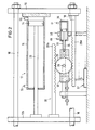
- a common drive means of the blow molded parts is provided for the closing and opening movements.
- the common hydraulic drive means 17 has a piston 14 which is displaceable in a cylinder 15, the piston rod 20 of which is connected to a carrier plate 12b which carries the one blow molded part 10b.
- the cylinder 15 is arranged on a drive plate 16 which is rigidly connected to the other carrier plate 12a by means of spars 18 which run through openings and guides 19 in the carrier plate 12b.
- the carrier plate 12a is arranged on the other side of the carrier plate 12b and carries the blow molded part 10a.
- the spars 18 and thus also the carrier plate 12a and the drive plate 16 are displaceably mounted on the base frame 4 by means of stands 5 which have corresponding guides. Further details of the blow molding machine are not shown for reasons of clarity.
- the blow molding device has a synchronizing device 30 with a gear 25 rotatably mounted on an axis 26, which meshes with toothed racks 28a and 28b, which in each case on the drive plate 16 or on the carrier plate 12b are attached. It is of course also possible to arrange the synchronizing device directly between the carrier plates 12a, 12b, so that the gear meshes with racks, which are each connected to a carrier plate. The same effect is achieved with both arrangements.
- the axis 26 is mounted in a holder 32, which can be displaced with respect to the base frame via bars 33 parallel to the opening and closing movements of the blow molded parts 10a, 10b. The displacement is effected by an additional drive means 38 designed as a hydraulic reciprocating piston, the piston rod 36 of which is connected to the holder 32 and the cylinder 35 of which is connected to the base frame 4.
- the extrusion head 22 of an extrusion device 23 is arranged above the blow molding parts 10a, 10b, from which the generally tubular preform 24 is extruded into the space between the two blow molding parts 10a, 10b of the then open blow mold.
- the preforms can be extruded from the extrusion head continuously or discontinuously.
- a preform 24 As soon as a preform 24 has a length required for the production of a hollow body, it is taken up by the blow mold by moving the blow mold parts 10a, 10b from their open state shown in FIG. 1 of the drawing by the drive means 17 into their closed state so that the mutually facing boundary surfaces 11 a, 11 abut each other and a mold cavity is delimited, within which the preform is expanded.
- actuation of the drive means 17 in the closing direction has the effect that, with the holder 32 of the synchronizing device 30 stationary, the carrier plate 12b is moved to the left and the drive plate 16 with the carrier plate 12a is moved to the same extent to the right, whereby the blow molded parts move symmetrically to a reference plane of the base frame 4, which generally corresponds to the central plane 9 of the preform 24.
- the center plane of the preform is therefore assumed to be the reference plane, without any limitation.
- the position of the gear wheel 25 of the synchronizing device 30 thus determines the position of the part dividing the distance between the two blow mold parts 10a, 10b Plane, which therefore always, ie regardless of the absolute position of this plane, runs in the middle between the two blow mold parts 10a, 10b or, in the case of an asymmetrical configuration thereof, in the middle between the two carrier plates 12a, 12b.
- This displacement of the blow mold is completely independent of the opening and closing movements of the blow mold parts caused by the common drive means 17, so that the displacement z. B. can also be carried out when the blow molded parts experience no movement relative to each other or are in their closed or open state.
- a path-time programmer 60 is provided, in which the desired path-time profiles and / or speed profiles of the blow mold parts 10a, 10b z. B. can be entered with respect to the median plane 9 of the preform. This means that the distance traveled by one of the blow mold parts is entered into the programmer 60 over the time and / or the speed at which the distance is covered.
- the programmer 60 is connected to a computing unit 62 which calculates the desired distance of the blow mold parts 10a, 10b from one another and / or their target speed relative to one another from the values entered in the programmer 60 and the resulting desired movements of the blow mold parts and a comparison and control device 49 as a target value.
- This device 49 controls, via the signal line 53, a valve 54 which is connected via lines 55, 56 to the cylinder 15 of the common drive system 17 and through which the volume flow of the hydraulic working medium, which is pumped to or returned from the cylinder 15, which corresponds to the closing and / or opening movement of the blow molded parts.
- the actual distance between the blow mold parts 10 a, 10 b is detected via a measuring sensor 50, which interacts with the blow mold parts 10 a, 10 b and is fed via the signal line 51 to the comparison and control device 49, which, if the actual value deviates from the target value Position of valve 54 corrected accordingly.
- the direct detection of the distance between the blow molded parts or the carrier plates assigned to them is cheaper than the separate detection of the paths of the blow molded parts or their associated carrier plates relative to the base frame and the calculation of the distance from the paths. In the latter case, elastic deformations of the parts of the machine that absorb the closing forces can lead to inaccurate results.
- the programmer 60 is connected to a computing unit 64, in which the desired distance between the central plane of the blow molded parts and the central plane 9 of the preform 24 is calculated. Relative to the first-mentioned central plane, which is half the distance between the blow molded parts, i.e. in the middle between these runs, the movements of the blow molded parts are symmetrical, i.e. opposite.
- the distance-time profile of the two center planes to one another corresponds to the target value of the overlapping displacement and is predefined by the computing unit 64 via a line 45 to a comparison and control unit 42, which controls a valve 44 via the signal line 43, which controls the valve via the lines 46, 41 supplies the volume flow of hydraulic working medium required for the displacement to the drive means 38.
- the actual position (actual value) of the gear wheel 25 is detected by a displacement sensor 37 which interacts with the holder 32. Via the signal line 39, the displacement sensor 37 is connected to the comparison and control unit 42, which corrects the position of the valve 44 as a function of a deviation of the actual value from the target value specified by the computing unit 64.
- the axis 26 of the gear 25 is always at the same distance from the central plane of the blow molded parts, so that the determined distance between the central plane of the blow molded parts and the central plane 9 of the preform 24 corresponds to the required displacement of the blow mold and thus of the gear 25 with respect to the base frame.
- FIG. 2 shows the displaceable synchronous device on a larger scale than in FIG. 1.
- FIG. 3 shows another embodiment of a displaceable synchronizing device 30.
- This embodiment has a control lever 81 which is pivotably arranged on the axis 26 of the displaceable holder 32.
- lever rods 83a and 83b are articulated at the opposite ends of the control lever 81 and are connected to the drive plate 16 and the carrier plate 12b, respectively.
- This arrangement also ensures that the carrier plate and drive plate 16 move symmetrically to the axis 26, as when using a gearwheel meshing with toothed racks.
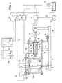
- the embodiment according to FIG. 4 differs from that according to FIG. 1 in particular in that the additional drive means 31 is arranged between the base frame and the drive plate 16, so that the piston rod 36 of the cylinder 35 attached to the base frame acts directly on the drive plate 16.
- the result of this arrangement is that the movements of the piston guided in the cylinder 35 are transmitted directly to the unit having the drive plate 16 and the carrier plate 12a.
- the movements of this unit 16, 12a therefore run synchronously with those of the piston guided in the cylinder 35.
- the latter also applies to the carrier plate 12b and thus to the blow molded part 10b carried by it, as long as the piston 14 and cylinder 15 of the common drive means 17 do not move relative to one another for the opening and closing movements.
- the carrier plate 12b executes a resulting movement with the blow molding part 10b, which movement is composed of the movement components of the additional drive means 31 and the common drive means 17.
- the arrangement of the common drive means 17 for opening and closing movements of the blow molded parts and its regulation correspond to the embodiment according to FIG. 1. Since the additional drive means 31 now acts on the drive plate 16 and thus causes its movements and that of the carrier plate 12a directly, Program generator 60, in which the path-time profiles of the individual blow mold parts are stored, the signal-line 45 of the comparison and control unit 42 the path-time profile of the blow mold part 10 a to the drive means 31 as the desired value.
- the additional drive means 31 engage directly on one of the carrier plates 12a or 12b.
- the program generator 60 would specify to the controller 42 the path-time profile of the blow molded part 10a or 10b connected to the additional drive means 31.
- the comparison and control unit 42 controls via the signal line 43 the valve 44, which determines the volume flow of hydraulic working medium required for the displacement of the drive plate 16.
- the displacement of the drive plate causes a corresponding movement of the blow molded part 10a due to the rigid connection through the bars 18 to the carrier plate 12a.
- the actual position of the drive plate 16 is detected by a displacement sensor 34 and input to the controller 42 as an actual value via the signal line 39.
- the comparison and control unit 42 corrects the position of the valve 44 if necessary.
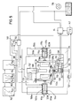
- FIGS. 5 to 7 show exemplary embodiments of blow molding devices in which drive systems are provided which have a separate drive means for each blow molded part, although there is otherwise broad agreement with the exemplary embodiment according to FIG. 1.
- FIGS. 5-7 the same parts are given the same parts, compared to those in FIGS. 1-4 are provided with 100 higher reference numerals.
- the blow molding machine according to FIG. 5 has two blow molding parts 110a, 110b, which are arranged on carrier plates 112a, 112b.
- a gear 125 is rotatably provided on an axis 126, which meshes with two toothed racks 128a, 128b, which are each connected to a carrier plate 112a or 112b.
- the holder 132, on which the gear 125 is arranged, can be displaced via an additional drive means 138 on the base frame parallel to the opening and closing movements of the blow molded parts.
- the control device for controlling the movement sequence of the blow molded parts largely corresponds to the control device according to FIG. 1. Since a separate drive means 117a, 117b is provided in each case, the hydraulic working medium to be supplied is downstream in the flow direction for the dimensioning of the given movements of the blow molded parts 110a, 110b required amount of hydraulic working medium provided valve 154 divided into two partial flows 156a, 156b. The hydraulic working medium displaced from the cylinders 115a, 115b is brought together in the flow direction upstream of the valve 154.
- the hydraulic drive means 117a, 117b are accordingly connected to one another via the lines 155a, 155b and 156a, 156b in such a way that the space 102a in front of the piston 114a with the space 102b in front of the piston 114b and the space 103a behind the piston 114a with the Space 103b is connected behind the piston 114b of the respective lifting cylinder 115a, 115b.
- the total amount of hydraulic working medium required for the predetermined closing movement of the blow molded parts is set by the valve 154 and conducted under pressure into the spaces 103a, 103b of the respective drive means 117a, 117b via the line 181 and the branch lines 156a, 156b , while at the same time the hydraulic working medium is discharged from the spaces 102a, 102b of the drive means via the branch lines 155a, 155b and the collecting line 183.
- the holder 132 of the gear wheel 125 is stationary, the total amount of hydraulic working medium supplied is evenly distributed to the drive means 117a, 117b due to the symmetrical movements of the blow molded parts which are thereby forced.
- the drive means 117a receives more hydraulic working medium, while the drive means 117b receives less accordingly, so that one piston 114a corresponding to the more supplied quantity of hydraulic working medium an additional, the other piston 114b according to the less supplied quantity one by the additional Reduced path of the piston 114a runs through with the effect that the two blow mold parts 110a, 110b and thus the blow mold experience a displacement in the direction of the displacement of the holder 132 independently of the continuing closing movement of the blow mold parts 110a, 110b.
- the hydraulic working medium is supplied to the spaces 102a, 102b, where it may experience a distribution corresponding to the displacement of the gear 125.
- the position of the gear wheel 125 also directly defines the position of the distance between the two blow molded parts 110a, 110b dividing middle plane. This means that the axis 126 is positioned in this central plane.
- gear 125 is in its neutral position. That is, the above-mentioned central plane of the blow molded parts coincides with the central plane 109 defined by the preform 124.
- FIG. 6 corresponds to that of FIG. 5, but the displacement of the blow mold is brought about by an additional drive means 131, which is arranged between the base frame 104 (not shown here) and the carrier plate 112b.
- the additional drive means 131 must therefore pass through the path-time profile of the blow molded part 110b predetermined by the programmer 160.
- the control elements provided for this drive means 131 therefore correspond to those of the blow molding device according to FIG. 4. If, for example, according to the program stored in the program generator 160, the blow molding part 110b is to perform a slower movement relative to the central plane 109 of the preform 124, the additional load is applied in this way Drive means 131 that the carrier plate 112b executes the movement assigned to it by the program.
- each of the two drive means 117a, 117b has its own valve analogous to valve 154 and / or its own control circuit would be unsuitable, since in particular in the last phase of the closing process, within which increased forces, e.g. B.
- FIG. 7 shows a further possibility of causing the displacement of the blow mold in addition to the opening and closing movements of the blow mold parts 110a, 110b in a blow molding machine which has a separate hydraulic drive means for each blow mold part.
- the displacement of the connecting element of the synchronizing device or the forced implementation of the path-time profile of a blow molded part by means of an additional drive means that the total amount of hydraulic working medium supplied is distributed unevenly in such a way that the respective one The amount of hydraulic working medium supplied to the drive means corresponds to the predetermined movement of the respective blow molded part in accordance with the value entered in the programmer 160.
- the predetermined movements of the blow molded parts relative to one another are brought about by the total amount of hydraulic working medium supplied in accordance with the target value determined by the computing unit 162, the amount being measured by the valve 154 before the division into the branch lines 155a, 155b, 156a, 156b.
- the distribution of the working medium is not necessarily brought about by an additional force acting on at least one of the blow molded parts, but by a distributing device.
- a program generator 160 is provided, in which the path-time profiles or speed profiles for each blow molding 110a, 110b relative to e.g. the middle plane 109 of the preform can be entered.
- the resulting distance-time profile or speed profile of the blow mold parts relative to one another is determined in the computing unit 162 and is given to a comparison and control device 149, which controls the valve 154, by means of which the hydraulic quantity required for the respectively predetermined movement Working medium is set.
- the programmer 160 is also connected to a computing unit 164, in which the displacement of the blow mold required for the desired asymmetrical movement of the blow mold parts with respect to the central plane 109 of the preform is determined, based on a specific distribution of the total hydraulic working medium supplied to the two drive means 117 a, 117b corresponds.
- the relations according to which the distribution has to be carried out are specified to a comparison and control unit 142, which controls a quantity distribution valve 171 for the supplied volume flow 181 and a quantity distribution valve 173 for the displaced volume flow 183 of the hydraulic working medium, the name of the supplied or displaced volume flows relates to the closing movements of the blow molded parts. With the opening movements, the flow direction of the volume flows is opposite.
- the drive means 117a, 117b are connected via lines 156a, 156b and 155a, 155b to the respective outputs or inputs of the quantity distribution valves 171 and 173, respectively.
- a measuring sensor 137 is provided, which is connected via the signal line 139 to the comparison and control device 142, which depends on a deviation of the actual value from the target calculated in the computer 164 - Corrected the valve position of the volume distribution valves 171, 173. It may be expedient to couple the volume distribution valves to one another via a line 174, since the displaced volume flow corresponds at least approximately to the supplied working medium due to the almost complete incompressibility of the hydraulic working medium.
- the sensor 137 is arranged on a displaceable synchronizing device 130, the structure of which corresponds to the synchronizing devices in FIGS. 1, 2 or 5, so that the displacement of the gear 125 corresponds to the actual displacement of the blow mold.
- the position of the axis 126 directly defines the median plane of the blow mold, since it runs in this median plane.
- the sensor z. B. to arrange on a blow molded part or a carrier plate, but then the valves 171, 173 are set depending on the comparison of the actual position of the corresponding blow molded part with the path-time curve for this blow molded part.
- blow mold is displaced by an additional drive system, which leads to a corresponding distribution of the hydraulic working medium, additionally to provide a distribution device for the total amount of hydraulic working medium supplied.
- the setting of the required quantity distribution valves e.g. can correspond to the volume distribution valves 171, 173, depending on the displacement of the connecting element.
- synchronizing devices 30, 130 are shown in the corresponding figures without the possibility of locking.
- Locking movable synchronizing devices is, however, possible by conventional means, e.g. possible by means of bolts or claws engaging in the recess or by means of frictional engagement, which therefore need not be shown in more detail.
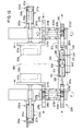
- FIGS. 8-10 also show exemplary embodiments of blow molding devices in which each blow molded part is provided with a separate drive means.
- the two exemplary embodiments according to FIGS. 8 and 9 largely agree with the embodiment according to FIG. 5, but in principle also with that according to FIG. 1, so that in FIGS. 8 and 9 parts which correspond to those of the exemplary embodiments already described, are provided with the same reference numerals, but 100 more than in FIG. 5 and thus 200 more than in FIG. 1.
- a synchronizing device having a gearwheel 225 and two toothed racks 228a, 228b is also provided, but the holder 232, which carries the axis 226 for the gearwheel 225, is fixedly attached to the machine frame 204.
- the holder 232 which carries the axis 226 for the gearwheel 225, is fixedly attached to the machine frame 204.
- one of the two racks namely the rack 228a
- the cylinder 235 of this drive means 238 is fixedly connected to the carrier plate 212a for the blow molding 210a.
- the movement of the blow molded parts 210a, 210b is thus not caused by a displacement of the gear 236, but by changing the effective length of another connecting element of the synchronizing device, namely the rack 228a .
- the effective length is changed by appropriately acting on the piston 240 guided in the cylinder 235 by the valve 244, which is controlled in the manner already described in connection with FIGS. 1 and 5 by a comparison and control unit 242.
- the latter is connected via the line 245 to the computing unit 264, in which the respective desired distance between the central plane of the blow molded parts and the central plane 209 of the preform 224 is calculated.
- the position of the median plane of the blow molded parts is determined by the position of the piston 240 relative to the cylinder 235 and thus to the carrier plate 212a carrying this cylinder. 8, the piston 240 takes its neutral, i.e. middle position in which the center plane of the two blow mold parts 210a, 210b coincides with the center plane 209 defined by the preform 224. Acting on the cylinder 235 on one of the two sides of the piston 240 has the result of the longitudinal displacement of the rack 228a which results in a rectified displacement of the two blow molded parts 210a, 210b, so that a displacement of e.g. B. the gear 125 in the embodiment according to FIG.
- FIG. 9 corresponds in all essential details with that of FIG. 8, so that the same reference numerals are used for corresponding parts.
- the only difference between the two versions relates to the design of the synchronizing device, which in the case of FIG. 9 consists of a chain, a cable or a similar endless flexible part 225 which is arranged around two wheels, disks or the like which are at a distance from one another chen 226a, 226b is performed.
- the two wheels or the like 226a, 226b are rotatably mounted on the machine frame 204.
- the arrangement is such that the directions in which the chain or the like 235 moves run parallel to the directions in which the two blow mold parts 210a, 210b execute their opening and closing movements.
- Both blow molded parts 210a, 210b or their carrier plates 212a, 212b are connected to the endless part 225 via essentially rigid connecting elements 228a, 228b such that the connecting element 228a with one section 225a and the other connecting element 228b with the other section 225b of the endless Part 225 is connected.
- the connecting element 228a is attached to the piston rod 236 of a piston which is guided in a cylinder 235. In the embodiment corresponding to FIG. 8, the latter is firmly connected to the carrier plate 212a of the blow molded part 210a.
- the same mode of operation results as in the exemplary embodiment according to FIG. 8.
- each of the two carrier plates 312a, 312b is provided with a rack 328a, 328b of a synchronous system, but the racks 328a, 328b are, however, attached to the side of the carrier plate facing away from the respective blow molding 310a, 310b.
- the toothings are arranged on opposite sides in such a way that the toothing of the toothed rack 328a is turned towards the viewer on the basis of the illustration in FIG.
- a gear wheel 325a, 325b is assigned to each of the two toothed racks 328a, 328b.
- Each gearwheel is fixedly connected to a shaft 326a or 326b, which ends downward from the respectively associated gearwheel 325a or 325b in a region which, based on the illustration in FIG. 10, is located below the carrier plates 312a, 312b or the blow mold parts 310a, 310b carried by these lies.
- Each of the two shafts 326a, 326b has a gear 325a 'and 325b' at its lower end.
- a common rack 390 is assigned to these two gearwheels 325a ', 325b'.
- the latter has two rack sections 392a, 392b, which are connected to one another by a cylinder-piston unit 338.
- the piston 340 guided in the cylinder 335 of this unit is provided with a piston rod 336, one end of which is fixedly connected to the rack section 392a, which meshes with the gear 325a '.
- the other end of the piston rod 336 carries a part 397 of a displacement transducer 337, through which the actual position (actual value) of the piston 340 to the cylinder 335 is detected and is passed via a line 339 to a comparison and control unit, which for example is the unit 242 corresponds to FIG. 9.
- the end region of the piston rod 336 which carries the part 397 of the displacement transducer 337 is passed through the end boundary 396 of the cylinder 335, the opening required for this purpose being provided in the end boundary 396 with sealing means which prevent the hydraulic pressure medium from escaping.
- the connection between the section 392 of the rack 390 and the cylinder 335 takes place via a connecting rod 398 and a housing 393 which is fixedly connected to the cylinder 335 and is provided with a slot-like passage for the part 397 of the displacement sensor 337.
- the rack 390 represents the length-adjustable kinematic connecting link of the elements of the synchronizing device 330 assigned to the blow molding parts 310a, 310b.
- This rack 390 is arranged so that it can be moved back and forth in the direction of its longitudinal axis can follow the rotational movements of the two gears 325a ', 325b' by executing a corresponding longitudinal displacement.
- the cylinder-piston unit 338 has the function of the drives 238 of the two exemplary embodiments according to FIGS. 8 and 9. Accordingly, the two lines 341 and 346 are connected to a valve which fulfills the function of the valve 244 in the exemplary embodiment according to FIGS. 8 and 9. Including the displacement sensor 337 and the connecting line 339, the circuit then results, which is also shown in FIGS. 8 and 9. This also applies to the other parts and arrangements, which can also be designed in the manner corresponding to FIGS. 8 and 9, but also in a manner corresponding to FIG. 7, in which case, however, the unit 338 would only have the function of a position transmitter.
- the guide means 395a, 395b for the rack 328a and 328b shown in FIG. 10 of the drawing, the guide means 398a, 398b for the rack sections 392a, 392b and the guide means 399a, 399b for the shaft 326a and 326b are each fixed on the machine frame 304 appropriate.
- FIG. 11 shows possible path-time profiles A (t), B (t) of the individual blow molded parts 10a; 110a; 210a; 310a and 10b; 110b; 210; 310b with respect to the neutral plane 9; 109; 209; 309 of the preform, the resulting distance-time profile S (t) of the blow mold parts relative to one another and the resulting required displacement profile V (t) (dashed line) of the blow mold in its entirety is shown schematically.
- the path is plotted on the horizontal axis, the zero in terms of value on the neutral central plane 9; 109; 209; 309 lies.
- the path-time profiles A (t), B (t) are e.g. B. in programmer 60; 160; 260 entered.
- the distance-time profile S (t) of the blow mold parts 10a, 10b; 110a, 11 ob; 210a, 210b; 310a, 310b calculated to each other.
- the distance-time profile V (t) of the central plane of the blow mold parts 10a, 10b; 110a, 110b; 210a, 210b; 310a, 310b to neutral plane 9; 109; 209; 309 of the preform determined.
- the distance-time curve V (t) corresponds to the displacement-time curve of the blow mold or the central plane of its blow mold parts.
- the blow molded parts move symmetrically, ie at the same speed, in the direction of the neutral plane 9; 109; 209; 309 of the preform, which coincides with the central plane of the blow mold.
- the speed at which the blow mold parts approach each other is twice as high in time period 1 as the speed of an individual blow mold part with respect to the reference plane 9; 109; 209; 309.
- the blow molded part 10a, 110a, 210a, 310a does not move, although the closing speed of the blow molded parts relative to one another remains unchanged.
- the connecting element of the synchronizing device moves from its neutral position with the result that the central plane of the blow mold is displaced in the direction of the blow mold part 10a, 110a in accordance with the extent of this movement, following the line V (t).
- the additional drive system that drives the displaceable connecting element in the embodiments according to FIGS. 1, 3 and 5 must therefore travel exactly this distance V (t). In the embodiment according to FIG. 5, this is achieved in that the total working medium supplied reaches only the drive means which is assigned to the blow molding to be moved.
- the blow molded part 10b, 110b, 210b, 310b experiences no movement under corresponding conditions, so that the reciprocal operating states of phase 11 are present.
- the additional drive means performs the predetermined movement of the blow molding part 11 Ob connected to the additional drive means, this movement simultaneously also the lifting movement of the Corresponds to drive means 131 for the closing movement and the drive means for the stationary blow molded part does not receive any hydraulic working medium.
- the quantity distribution valve in phase 11 or 111 would be set such that the valve slide 171 or the corresponding functional element completely closes the supply line assigned to the stationary blow molding part, so that the previously dimensioned one Amount of hydraulic working medium is led exclusively to the drive means which is connected to the blow mold part in each case moved.
- the blow molding part 10b, 11 Ob, 210b, 310b moves faster in the direction of the central plane 9, 109, 209, 309 or zero plane O, while in the last time period VI the blow molding part 10a, 110a, 210a, 310a moves faster .
- the blow mold undergoes an additional displacement at a speed which corresponds to half the sum of the speeds of the individual blow mold parts and runs in the direction of the slower blow mold part, the respective speeds with the respective sign corresponding to their direction (+, - ) are provided. This condition applies in general.
- the target values for closing movement and for opening movement and for additional displacement can be obtained by entering the path-time profiles A (t) and B (t) in a coordinate network, the time axis of which along the neutral plane 9; 109; 209; 309 and its path axis runs parallel to the opening and closing movements.
- the distance-time profile of the blow molded parts to one another then results from the relationship: if B (t) is entered on the positive section and A (t) on the negative section of the path axis, the zero in terms of value being located on the center axis 9, 109, 209, 309.
- the target value for the required displacement of the adjustable connecting member and thus the blow mold then results for the exemplary embodiments with a displaceable gearwheel 25; 125 or control lever 81 of the synchronizing device according to where the sign defines the position in relation to the zero line. This corresponds to the dashed representation in FIG. 11.
- gear ratios of the interacting parts are 1: 1.
- other gear ratios are also possible, which then lead to corresponding changes in the relations between the movements of the individual parts.
- FIG. 12 Another possible movement sequence of the blow molded parts during the closing phase is shown in FIG. 12, which is divided into three areas 1-3.
- area 3 at the end of the closing phase for the blow molded parts 10a, 10b; 110a, 110b; 210a, 210b; 310a, 310b provided movements that meet the requirements for squeezing the waste material and welding the seam areas.
- Movements A (t), B (t) of the blow molded parts can be predetermined in area 1 of the movement sequence at the beginning of the closing phase. In this case, they have time periods I-V which correspond to the time periods I-V of FIG. 11 and therefore do not require any further explanation.
- the area 2 represents a transition area in which the blow molded parts are brought from their end position after their movement according to area 1 into the start position for area 3.
- a program which has three sections corresponding to the three areas 1-3. Any path-time profiles A (t), B (t) can then be specified in the first section, the movements of the blow molded parts being calculated in the second section, so that the blow molded parts reach the start positions of the third section from the end positions of the first section which is fixed within the program.
- the movements that are required to squeeze the waste materials and to weld the seam areas for the respective application are stored in accordance with the above explanations.
- curve profiles shown in FIGS. 11 and 12 are composed of sharply delimited sections for better understanding. However, it will be expedient to provide curves which have transition areas.
- the other rack is designed or arranged in such a way that its effective length can be changed.
- the exemplary embodiment according to FIG. 1 which has only one common drive means for the opening and closing movement of the blow molded parts, to design one of the two toothed racks with respect to their effective length so that they can be changed, that is to say analogously, for example, instead of the gear wheel of the synchronizing device which changes its position Embodiment according to FIG. 8. It would then also apply that the setpoint V (t) for the displacement of the piston in the cylinder of the synchronizing device is calculated according to the equation given above for the exemplary embodiments according to FIGS. 8-10.
Landscapes
- Engineering & Computer Science (AREA)
- Mechanical Engineering (AREA)
- Manufacturing & Machinery (AREA)
- Blow-Moulding Or Thermoforming Of Plastics Or The Like (AREA)
- Moulds For Moulding Plastics Or The Like (AREA)
- Spinning Methods And Devices For Manufacturing Artificial Fibers (AREA)
- Extrusion Moulding Of Plastics Or The Like (AREA)
- Laminated Bodies (AREA)
Abstract
Description
Die Erfindung betrifft ein Verfahren und eine Vorrichtung zur Herstellung von Hohlkörpern aus thermoplastischem Kunststoff mittels Blasformen, wobei ein vorzugsweise schlauchförmiger Vorformling von einer wenigstens zwei Blasformteile aufweisenden Blasform aufgenommen und unter innerem Überdruck darin aufgeweitet wird und beide Teile der Blasform zwischen einem Offenzustand, in welchem sie einen Abstand voneinander aufweisen, und einem Schließzustand, in welchem sie aneinander anliegen und ein Formnest begrenzen, dessen Kontur der Gestalt des durch inneren Überdruck aufgeweiteten Vorformlings entspricht, durch wenigstens ein die Bewegungen zwischen diesen Zuständen bewirkendes Antriebssystem hin- und herbewegt werden.The invention relates to a method and a device for producing hollow bodies made of thermoplastic material by means of blow molding, a preferably tubular preform being taken up by a blow mold having at least two blow molded parts and being expanded therein under internal pressure, and both parts of the blow mold between an open state in which they are have a distance from one another, and a closed state in which they abut one another and delimit a mold cavity, the contour of which corresponds to the shape of the preform widened by internal overpressure, are moved back and forth by at least one drive system causing the movements between these states.
Bei den Schließ- und Öffnungsbewegungen der Blasformteile ist es im allgemeinen erforderlich, daß diese Bewegungen bezüglich einer Bezugsebene des Grundrahmens der Blasformmaschine definiert und jederzeit reproduzierbar ablaufen. Üblicherweise wird dabei so verfahren, daß sich die Blasformteile symmetrisch auf die Mittelebene eines in der Mitte zwischen ihnen befindlichen Vorformlings hin- bzw. sich von dem daraus durch Aufweiten hergestellten Hohlkörper wegbewegen. Es wird daher im folgenden überwiegend die Mittelebene des im allgemeinen frei hängenden Vorformlings als Bezugsebene angenommen, wenngleich auch andere Bezugsebenen definiert werden können.In the closing and opening movements of the blow molded parts, it is generally necessary that these movements are defined with respect to a reference plane of the base frame of the blow molding machine and are reproducible at all times. Usually the procedure is such that the blow molded parts move symmetrically towards the center plane of a preform located between them or move away from the hollow body produced therefrom by expansion. In the following, therefore, the central plane of the generally freely suspended preform is predominantly assumed as the reference plane, although other reference planes can also be defined.
Insbesondere bei Verwendung eines hydraulischen Antriebssystems für die Schließ- und Öffnungsbewegungen der Blasformteile ist es aufgrund der Eigenschaften der dabei verwendeten Antriebsmittel ohne zusätzliche Vorkehrungen nicht möglich, den erwünschten Gleichlauf der Formteile bei den Schließ- und Öffnungsbewegungen bezüglich des Vorformlings zu erzielen, so daß die Gefahr besteht, daß die Formteile aufgrund unterschiedlicher Geschwindigkeiten ihren Öffnungs-oder Schließzustand jeweils in nicht definierbaren Positionen erreichen. Derartige Unregelmäßigkeiten bei den Bewegungen der Blasformteile sind im allgemeinen unerwünscht, zumal sie in unkontrollierbarer und somit von Arbeitszyklus zu Arbeitszyklus unterschiedlicher Weise auftreten können.In particular when using a hydraulic drive system for the closing and opening movements of the blow molded parts, it is not possible due to the properties of the drive means used without additional precautions to achieve the desired synchronization of the molded parts during the closing and opening movements with respect to the preform, so that the danger there is that the molded parts each reach their open or closed state in non-definable positions due to different speeds. Such irregularities in the movements of the blow molded parts are generally undesirable, especially since they can occur in an uncontrollable manner and thus in different ways from one working cycle to another.
Zur Vermeidung solcher Unregelmäßigkeiten werden als zusätzliche Vorkehrung Gleichlaufeinrichtungen vorgesehen, die einen definierten Bewegungsablauf der Formteile relativ zu einer Bezugsebene des Grundrahmens bewirken. Im allgemeinen ist die Anordnung so getroffen, daß die Gleichlaufeinrichtung wenigstens ein mechanisches Verbindungselement aufweist, das nicht verschiebbar am Grundrahmen der Blasformmaschine angeordnet ist und durch welches die Blasformteile miteinander kinematisch gekoppelt sind. Aufgrund der festen Anordnung des Verbindungselements am Grundrahmen wird erreicht, daß die Schließ- und Öffnungsbewegungen der Blasformteile relativ zu der Mittelebene des Vorformlings bzw. des daraus hergestellten Artikels gleichartig entgegensetzt ablaufen. Dadurch wird mit einfachen Mitteln erreicht, daß die Formteile sich symmetrisch schließen und öffnen und somit ihren Schließzustand bzw. Offenzustand in definierten Positionen erreichen.To avoid such irregularities, synchronizing devices are provided as an additional precaution, which bring about a defined movement sequence of the molded parts relative to a reference plane of the base frame. In general, the arrangement is such that the synchronizing device has at least one mechanical connecting element which is not displaceably arranged on the base frame of the blow molding machine and by means of which the blow molded parts are kinematically coupled to one another. Due to the fixed arrangement of the connecting element on the base frame it is achieved that the closing and opening movements of the blow molded parts relative to the median plane of the preform or the article made therefrom run in opposite directions. It is thereby achieved with simple means that the molded parts close and open symmetrically and thus reach their closed or open state in defined positions.
Bei einer bekannten Gleichlaufeinrichtung ist als Verbindungselement ein Zahnrad drehbar auf einer Achse angeordnet, die am Grundrahmen der Blasformmaschine fest angebracht ist. Die beiden Blasformteile weisen Zahnstangen auf, die mit dem Zahnrad kämmen. Bei einer Bewegung des einen Blasformteils wird das Zahnrad durch die entsprechende Zahnstange gedreht mit der Folge, daß das andere Blasformteil, dessen zugeordnete Zahnstange parallel zu der anderen Zahnstange auf der anderen Seite der Achse angeordnet ist, in die entgegengesetzte Richtung bewegt wird. Bei einer anderen Ausführungsform der Gleichlaufeinrichtung ist ein Steuerhebel schwenkbar um eine ortsfeste Achse am Grundrahmen gelagert. An den beiden gleich langen Hebelarmen sind Stangen verschwenkbar angeordnet, die mit ihrem anderen Ende beweglich an jeweils einem Blasformteil angebracht sind. Die Blasformteile sind über derartige Anordnungen kinematisch zwangsweise miteinander und mit dem Grundrahmen der Blasformmaschine gekoppelt. Es werden auch andere Gleichlaufeinrichtungen verwendet, die jedem Fachmann geläufig sind und keiner näheren Erläuterung bedürfen. Es kann sich dabei um z. B. um Gleichlaufeinrichtungen mit einem endlosen, flexiblen Element, z. B. einer Kette, einem Seil oder dgl. handeln, welches um zwei rotierbar, jedoch nicht verschiebbar am Maschinenrahmen angebrachte Räder, Rollen oder dgl. geführt ist. Allen Ausführungsformen ist jedoch gemeinsam, daß sie wenigstens ein Glied aufweisen, welches stationär, wenn auch rotierbar am Grundrahmen der Blasformmaschine angeordnet ist und somit eine Bezugsebene festlegt, relativ zu welcher die Bewegungen der Blasformteile symmetrisch entgegengesetzt ablaufen. Die Bezugsebene ist dabei im allgemeinen so gewählt, das sie mit der Mittelebene des Vorformlings zusammenfällt. In dieser Mittelebene wird häufig auch der Blasdorn angeordnet sein, der mit der Blasform und dem Vorformling zusammenwirkt und durch welchen i. a. das zum Aufweiten erforderliche Druckmedium in die Blasform geleitet wird.In a known synchronous device, a gear wheel is rotatably arranged on an axis as a connecting element, which is fixedly attached to the base frame of the blow molding machine. The two blow molded parts have racks that mesh with the gear. When the one blow molding part is moved, the gear wheel is rotated by the corresponding rack, with the result that the other blow molding part, whose associated rack is arranged parallel to the other rack on the other side of the axis, is moved in the opposite direction. In another embodiment of the synchronizing device, a control lever is pivotally mounted on the base frame about a fixed axis. Rods are pivotally arranged on the two lever arms of equal length, the other end of which is movably attached to a blow molding part. The blow molded parts are forcibly kinematically coupled to one another and to the base frame of the blow molding machine via such arrangements. Other synchronizing devices are also used which are familiar to any person skilled in the art and which require no further explanation. It can be z. B. to synchronous devices with an endless, flexible element, for. B. act a chain, a rope or the like. Which is guided by two rotatable, but not slidably mounted on the machine frame wheels, rollers or the like .. However, all embodiments have in common that they have at least one link which is arranged in a stationary, if rotatable, manner on the base frame of the blow molding machine and thus defines a reference plane relative to which the movements of the blow molded parts run symmetrically in opposite directions. The reference plane is generally chosen so that it coincides with the median plane of the preform. The blowing mandrel, which interacts with the blow mold and the preform and through which i. a. the pressure medium required for expansion is passed into the blow mold.
Ein möglicher Aufbau einer solchen Blasformmaschine ergibt sich z. B. aus US-PS 4,150,080, deren Offenbarungsgehalt in diese Anmeldung einbezogen wird.A possible structure of such a blow molding machine results, for. B. from US-PS 4,150,080, the disclosure content is included in this application.
Insbesondere in der letzten Phase des Schließvorganges wird eine derartige symmetrische Bewegung der Formteile häufig erwünscht sein, da die beiden Blasformteile in dieser Phase den an einem Extrusionskopf oder an anderen geeigneten Haltemitteln hängenden Vorformling umfassen und das vorhandene Abfallmaterial in bekannter Weise abquetschen, wobei gleichzeitig die aneinanderliegenden Bereiche des Vorformlings miteinander verschweißt werden. In der Mehrzahl der Fälle wird der Vorformling, wenn er seine Aufnahmeposition einnimmt, in welcher er von der Blasform aufgenommen wird, am Extrusionskopf einer Extrusionsvorrichtung hängen. Es ist aber auch möglich, daß der Vorformling, der auch in anderer Weise als durch Extrudieren hergestellt sein kann, von einer anderen Halterung in seiner Aufnahmeposition gehalten wird, bis er von der Blasform aufgenommen worden ist.Such a symmetrical movement is especially in the last phase of the closing process tion of the molded parts are often desirable, since the two blow molded parts in this phase comprise the preform hanging from an extrusion head or other suitable holding means and squeeze off the existing waste material in a known manner, the adjacent areas of the preform being welded to one another at the same time. In the majority of cases, when the preform is in its receiving position in which it is received by the blow mold, it will hang on the extrusion head of an extrusion device. However, it is also possible for the preform, which can also be produced in a manner other than extrusion, to be held in its receiving position by another holder until it has been taken up by the blow mold.
Im Zuge der Ausweitung der Anwendung des Blasformverfahrens, insbesondere auch zur Herstellung von Hohlkörpern mit sehr komplizierter Gestalt, hat sich herausgestellt, daß die vorbeschriebenen üblichen, relativ zum Vorformling symmetrischen Bewegungen der Blasformteile nicht immer vorteilhaft sind, zumal die Blasform nicht in allen Fällen symmetrisch unterteilt ist mit der Folge, daß die Blasformteile unterschiedlich ausgestaltet sind. Es gibt daher Anwendungsmöglichkeiten, bei denen es zweckmäßiger, ggf. sogar erforderlich sein kann, Bewegungen der Blasformteile so durchzuführen, daß sie relativ zum Vorformling asymmetrisch ablaufen. Dies kann auch für die Öffnungsbewegungen der Blasformteile in Bezug auf den hergestellten Artikel gelten, der im allgemeinen von dem Blasdorn oder einem anderen mit der Blasform zusammenwirkenden Teil gehalten wird, welches an den Öffnungsbewegungen nicht teilnimmt.In the course of the expansion of the use of the blow molding process, in particular also for the production of hollow bodies with a very complicated shape, it has emerged that the above-described usual movements of the blow mold parts which are symmetrical relative to the preform are not always advantageous, especially since the blow mold is not symmetrically divided in all cases is the consequence that the blow molded parts are designed differently. There are therefore possible applications in which it may be more appropriate, possibly even necessary, to carry out movements of the blow molded parts in such a way that they run asymmetrically relative to the preform. This can also apply to the opening movements of the blow mold parts in relation to the manufactured article, which is generally held by the blow mandrel or another part which interacts with the blow mold and does not take part in the opening movements.
Der Erfindung liegt daher die Aufgabe zugrunde, Verfahren und Vorrichtung der einleitend beschriebenen Art so auszugestalten, daß im Bedarfsfall auf einfache und jederzeit reproduzierbare Weise die Schließ- und auch die Öffnungsbewegungen der Blasformteile relativ zum Vorformling asymmetrisch ablaufen können, und zwar unter Einhaltung der für die Herstellung solcher Hohlkörper notwendigen Genauigkeit der Blasformteilbewegungen. Die dazu erforderlichen Mittel sollen einfach und wenig aufwendig sein.The invention is therefore based on the object to design the method and apparatus of the type described in the introduction so that, if necessary, the closing and also the opening movements of the blow molded parts can run asymmetrically relative to the preform, in a simple and reproducible manner, while observing the requirements for Production of such hollow bodies necessary accuracy of the blow molding movements. The means required for this should be simple and inexpensive.
Zur Lösung dieser Aufgabe schlägt die Erfindung vor, die Blasform zumindest zeitweilig auch während der Zeitabschnitte, innerhalb welcher die Schließ- und/oder Öffnungsbewegungen stattfinden, in einer parallel zu den Schließ- und Öffnungsbewegungen verlaufenden Richtung zu verschieben. Dadurch wird den jeweiligen Schließ- oder Öffnungsbewegungen der Blasformteile eine zusätzliche Bewegung überlagert mit der Folge, daß die Blasformteile sich mit unterschiedlichen Geschwindigkeiten und somit asymmetrisch relativ zu einer Bezugsebene des Grundrahmens der Blasformmaschine, also im allgemeinen auf den Vorformling hin- bzw. vom aufgeweiteten Hohlkörper wegbewegen. Die Verschiebung, die die Blasform in ihrer Gesamtheit erfährt, kann erfindungsgemäß in unterschiedlicher Weise erfolgen und hängt auch von dem die Schließ- und Öffnungsbewegungen bewirkenden Antriebssystem ab.To achieve this object, the invention proposes to move the blow mold, at least temporarily, also in the direction during which the closing and / or opening movements take place, in a direction running parallel to the closing and opening movements. As a result, an additional movement is superimposed on the respective closing or opening movements of the blow molded parts, with the result that the blow molded parts move at different speeds and thus asymmetrically relative to a reference plane of the base frame of the blow molding machine, i.e. generally towards the preform or from the expanded hollow body move away. The displacement, which the blow mold experiences in its entirety, can take place according to the invention in different ways and also depends on the drive system which effects the closing and opening movements.
Die Antriebssysteme für die Bewegungen der Blasformteile können sich unter anderem durch die Art der Antriebsmittel oder durch den Aufbau der die Blasformteile tragenden Schließeinheit voneinander unterscheiden. So kann für die Blasformteile ein gemeinsames Antriebsmittel vorgesehen sein. Es ist auch möglich, jedem Blasformteil ein eigenes Antriebsmittel zuzuordnen. Als Antriebsmittel werden wegen der hohen aufzuwendenden Kräfte überwiegend hydraulische Kolben-Zylindereinheiten eingesetzt. Im folgenden wird daher, ohne daß dies eine Beschränkung darstellen soll, überwiegend von hydraulischen Kolben-Zylindereinheiten gesprochen, wobei es selbstverständlich ist, daß derartige Einheiten auch mehrere, parallel wirkende Hydraulikzylinder aufweisen können.The drive systems for the movements of the blow molded parts can differ from one another, inter alia, by the type of drive means or by the structure of the closing unit carrying the blow molded parts. A common drive means can be provided for the blow molded parts. It is also possible to assign a separate drive means to each blow molding. Hydraulic piston-cylinder units are mainly used as the drive means due to the high forces to be applied. In the following, therefore, without this being intended to be a limitation, it is predominantly spoken of hydraulic piston-cylinder units, it being understood that such units can also have a plurality of hydraulic cylinders acting in parallel.
Bei einem sogenannten Dreiplatten-Schließgestell mit nur einem Antriebsmittel für die Schließ-und Öffnungsbewegungen der Blasformteile ist das gemeinsame Antriebsmittel zwischen einer ersten, ein Blasformteil tragende Trägerplatte und einer zu dieser parallel verlaufenden Antriebsplatte angeordnet, welche durch Holme oder dgl. mit einer zweiten, auf der anderen Seite der ersten Trägerplatte liegenden Trägerplatte starr verbunden ist, welche das andere Blasformteil trägt (vgl. z. B. Fig. 1). Ein Betätigen des Antriebs z.B. in Schließrichtung bewirkt, daß, wenn ein am Grundrahmen der Blasformmaschine fest angeordnetes Gleichlaufelement der einleitend beschriebenen Art die Blasformteile oder deren Trägerplatten kinematisch miteinander verbindet, sich die Blasformteile symmetrisch auf den Vorformling hinbewegen, während sich die Antriebsplatte im Ausmaß der Bewegung der zweiten Trägerplatte vom Vorformling wegbewegt.In a so-called three-plate locking frame with only one drive means for the closing and opening movements of the blow molded parts, the common drive means is arranged between a first support plate carrying a blow molded part and a drive plate running parallel to it, which is connected to a second one by bars or the like the other side of the first carrier plate is rigidly connected, which carries the other blow molded part (see, for example, Fig. 1). Actuating the drive e.g. In the closing direction, if a synchronous element of the type described in the introduction, which is fixedly arranged on the base frame of the blow molding machine, kinematically connects the blow mold parts or their carrier plates to one another, the blow mold parts move symmetrically towards the preform, while the drive plate moves from the preform to the extent of the movement of the second carrier plate moved away.
Die Verschiebung der Blasform kann erfindungsgemäß dadurch erfolgen, daß ein als kinematisches Verbindungselement wirkendes Glied der Gleichlaufeinrichtung am Grundrahmen, z.B. durch ein zusätzliches, unabhängiges Antriebssystem eine Verschiebung, also eine Änderung seiner Position, erfährt. Die Verschiebung des Verbindungselementes hat zur Folge, daß die gesamte bewegliche Einheit, die unter anderem die beiden Trägerplatten, die Antriebsplatte und das gemeinsame Antriebsmittel für die Schließ- und Öffnungsbewegungen aufweist, ebenfalls eine entsprechende Verschiebung erfährt.The displacement of the blow mold can take place according to the invention in that a link acting as a kinematic connecting element of the synchronizing device on the base frame, e.g. undergoes a shift, i.e. a change in its position, through an additional, independent drive system. The result of the displacement of the connecting element is that the entire movable unit, which includes the two carrier plates, the drive plate and the common drive means for the closing and opening movements, also undergoes a corresponding displacement.
Eine andere Möglichkeite besteht darin, daß wenigstens eines der Verbindungsglieder der Gleichlaufeinrichtung eine Änderung seiner wirksamen Länge erfährt, wobei dies durch ein zusätzliches, unabhängiges Antriebssystem erreicht werden kann. Dies hat ebenfalls die Wirkung, daß die Blasform in ihrer Gesamtheit eine Verschiebung erfährt.Another possibility is that at least one of the connecting links of the Synchronization device experiences a change in its effective length, which can be achieved by an additional, independent drive system. This also has the effect that the blow mold as a whole is displaced.
Es wird somit den Schließ- und/oder Öffnungsbewegungen in beiden Fällen eine zusätzliche Bewegung überlagert mit dem Ergebnis, daß die aus der jeweiligen Öffnungs- oder Schließbewegung der Blasformteile zueinander und der Verschiebung der Blasform in ihrer Gesamtheit resultierenden Bewegungen der Blasformteile relativ zum Vorformling asymmetrisch ablaufen. Die Schließ-und/oder Öffnungsbewegung der Blasformteile relativ zueinander und das dafür verwendete Antriebsmittel werden durch diese Verschiebung der Blasform nicht beeinflußt. Durch diese zwei unabhängig voneinander ablaufenden Bewegungen, nämlich die Schließ- und/oder Öffnungsbewegung einerseits und die Verschiebung andererseits, wird erreicht, daß nahezu jeder Weg-Zeit-Verlauf bzw. Geschwindigkeit-Verlauf der Blasformteile bezüglich des Vorformlings realisiert werden kann. Durch die Trennung dieser beiden Bewegungen und die Unabhängigkeit der dafür verwendeten Antriebssysteme voneinander wird andererseits erreicht, daß die Kraft zum Schließen der Blasform und zum Abquetschen des Abfallmaterials und die Kraft, die benötigt wird, um die Blasform in geschlossenem Zustand zu halten, wenn der Vorformling unter innerem Überdruck aufgeweitet wird, von der Verschiebung unbeeinflußt bleiben.There is thus an additional movement superimposed on the closing and / or opening movements in both cases, with the result that the movements of the blow mold parts resulting from the respective opening or closing movement of the blow mold parts relative to one another and the displacement of the blow mold as a whole run asymmetrically relative to the preform . The closing and / or opening movement of the blow mold parts relative to one another and the drive means used for this are not influenced by this displacement of the blow mold. These two movements, which run independently of one another, namely the closing and / or opening movement on the one hand and the displacement on the other hand, ensure that almost any path-time profile or speed profile of the blow molded parts can be realized with respect to the preform. The separation of these two movements and the independence of the drive systems used for this, on the other hand, ensures that the force for closing the blow mold and for squeezing the waste material and the force required to keep the blow mold in the closed state when the preform is expanded under internal pressure, remain unaffected by the shift.
Gemäß einem weiteren Vorschlag der Erfindung können der gewünschte Weg-Zeit-Verlauf und/oder Geschwindigkeit-Verlauf jedes Blasformteils bezüglich seiner Öffnungs- und/oder Schließbewegungen separat vorgegeben werden und die dafür benötigten Bewegungen des Antriebssystems, welches die Blasform schließt und öffnet, und des zusätzlichen Antriebssystems für die Verschiebung der Blasform in Abhängigkeit von diesen Weg-Zeit-Verläufen und/oder Geschwindigkeit-Zeit-Verläufen bestimmt werden. Dabei wird es zweckmäßig sein, für jedes Blasformteil ein Programm für den Weg-Zeit-Verlauf und/oder Geschwindigkeit-Verlauf vorzusehen, wobei es auch vorteilhaft sein kann, für die Schließbewegung und für die Öffnungsbewegung der Blasformteile jeweils ein separates Programm vorzusehen.According to a further proposal of the invention, the desired path-time profile and / or speed profile of each blow molding part with respect to its opening and / or closing movements can be specified separately and the movements required for this of the drive system, which closes and opens the blow mold, and the additional drive system for the displacement of the blow mold depending on these path-time profiles and / or speed-time profiles can be determined. It will be expedient to provide a program for the path-time profile and / or speed profile for each blow molding part, it also being advantageous to provide a separate program for the closing movement and for the opening movement of the blow molding parts.
Aus den gewünschten Weg-Zeit-Verläufen und/oder den Geschwindigkeit-Verläufen der Blasformteile bezüglich des Vorformlings läßt sich in einfacher Weise der erforderliche Schließ- und Öffnungsweg-Zeit-Verlauf bestimmen, der ausschließlich von dem Antriebssystem für die Schließ- und Öffnungsbewegungen bewirkt wird, indem der Abstand-Zeit-Verlauf der Blasformteile zueinander errechnet wird. Der Abstand-Zeit-Verlauf ist die Vorgabe (Soll-Wert) für das die Schließ- und Öffnungsbewegungen bewirkende Antriebssystem.From the desired path-time profiles and / or the speed profiles of the blow molded parts with respect to the preform, the required closing and opening path-time profile can be determined in a simple manner, which is exclusively caused by the drive system for the closing and opening movements by calculating the distance-time profile of the blow molded parts to one another. The distance-time curve is the specification (target value) for the drive system causing the closing and opening movements.
Die für die gewünschte asymmetrische Bewegung der Blasformteile bezüglich der Mittelebene des Vorformlings erforderliche Verschiebung der Blasform in ihrer Gesamtheit kann erfindungsgemäß dadurch bestimmt werden, daß der Abstand der Mittelebene zwischen den Blasformteilen von der Mittelebene des Vorformlings oder einer anderen Bezugsebene des Grundrahmens ermittelt wird. Die Mittelebene zwischen den Blasformteilen entspricht dabei einer Ebene, welche in dem halben Abstand der Blasformteile zueinander, d.h. mittig zwischen den Blasformteilen verläuft und relativ zu welcher die Bewegungen der Blasformteile gleichartig entgegengesetzt, also symmetrisch ablaufen. Der sich daraus ergebende Abstand-Zeit-Verlauf der beiden Mittelebenen entspricht der erforderlichen Verschiebung der Blasform und ist die Vorgabe (Soll-Wert) für das die Verschiebung bewirkende zusätzliche Antriebssystem. Es ist dabei erforderlich, außer dem Ausmaß auch die Richtung der Verschiebung zu ermitteln, da die Verschiebung der Blasform in beiden Richtungen erfolgen kann.The displacement of the blow mold in its entirety required for the desired asymmetrical movement of the blow mold parts with respect to the center plane of the preform can be determined according to the invention by determining the distance of the center plane between the blow mold parts from the center plane of the preform or another reference plane of the base frame. The center plane between the blow molded parts corresponds to a plane which is half the distance between the blow molded parts, i.e. runs in the middle between the blow mold parts and relative to which the movements of the blow mold parts run in the same opposite way, that is to say run symmetrically. The resulting distance-time profile of the two middle planes corresponds to the required displacement of the blow mold and is the specification (target value) for the additional drive system causing the displacement. It is necessary to determine the direction of the shift in addition to the extent, since the blow mold can be shifted in both directions.
Die asymmetrischen Bewegungen der Blasformteile lassen sich somit bei separater Vorgabe des Weg-Zeit-Verlaufs oder des Geschwindigkeit-Verlaufs der einzelnen Blasformteile durch die Überlagerung der Schließ- oder Öffnungsbewegungen und der Verschiebung der Blasform erreichen.The asymmetrical movements of the blow mold parts can thus be achieved by separately specifying the path-time curve or the speed curve of the individual blow mold parts by superimposing the closing or opening movements and shifting the blow mold.
Ferner ist es möglich, das Antriebsmittel des die Verschiebung der Blasform bewirkenden Antriebssystems an einer anderen Stelle als an dem Verbindungselement der Gleichlaufeinrichtung angreifen zu lassen. Es kann z.B. zweckmäßig sein, das Antriebsmittel zwischen einem Blasformteil und dem Grundrahmen der Blasformmaschine anzuordnen. In diesem Fall muß das zusätzliche Antriebssystem einen Verschiebeweg-Zeit-Verlauf bewirken, der dem jeweiligen Weg-Zeit-Verlauf des Blasformteils, das mit dem zusätzlichen Antriebssystem verbunden ist, entspricht. Es ist dabei nicht erforderlich, daß ein Verbindungselement vorgesehen wird, das die Blasformteile kinematisch miteinander koppelt, da sich der relativ zur Bezugsebene vorgegebene Weg-Zeit-Verlauf desjenigen Blasformteils, das nicht mit dem zusätzlichen Antriebssystem verbunden ist, aus der Differenzbewegung zwischen der Schließ- und/oder Öffnungsbewegung der Blasformteile zueinander einerseits und dem durch das zusätzliche Antriebssystem bewirkten Bewegung des damit verbundenen Blasformteils andererseits ergibt. Falls ein Verbindungselement vorhanden ist, muß sich dieses bezüglich seiner Position oder Länge zur Anpassung an die gewünschten asymmetrischen Bewegungen der Blasformteile bezüglich des Vorformlings frei einstellen können.Furthermore, it is possible to have the drive means of the drive system causing the displacement of the blow mold act at a location other than on the connecting element of the synchronizing device. For example, it may be appropriate to arrange the drive means between a blow molding part and the base frame of the blow molding machine. In this case, the additional drive system must bring about a displacement path-time curve which corresponds to the respective path-time curve of the blow molded part which is connected to the additional drive system. It is not necessary to provide a connecting element that kinematically couples the blow molded parts to one another, since the path-time profile of the blow molded part that is not relative to the reference plane and is not connected to the additional drive system results from the differential movement between the closing and / or opening movement of the blow molded parts relative to one another on the one hand and the movement of the associated blow molded part caused by the additional drive system results on the other hand. If a connecting element is present, it must adjust freely in terms of its position or length to adapt to the desired asymmetrical movements of the blow molded parts with respect to the preform can.
Bei der Ausführungsform einer Blasformmaschine, die ein Antriebssystem aufweist, bei welchem für jedes Blasformteil ein separates Antriebsmittel vorgesehen ist, ist jeweils zwischen dem Grundrahmen und den die Blasformteile tragenden Trägerplatten eine Kolben-Zylindereinheit angeordnet. Durch die gemeinsame Beaufschlagung der Hydraulikzylinder mit hydraulischem Arbeitsmedium bewegen sich die Blasformteile auf den Vorformling zu oder von ihm weg, wobei im allgemeinen ebenfalls eine Gleichlaufeinrichtung der einleitend beschriebenen Art vorgesehen ist, um symmetrische Bewegungen der Blasformteile zum Vorformling zu erzeugen. Auch bei einer derartigen Blasformmaschine kann zur Erzielung der gewünschten asymmetrischen Bewegungen der Blasformteile zusätzlich die Blasform in ihrer Gesamtheit verschoben werden, indem z. B. das Verbindungselement eine Verschiebung erfährt. Eine Verschiebung der Blasform entspricht auch bei derartigen Blasformmaschinen einer Verschiebung oder Längenänderung der Gleichlaufeinrichtung mit einem Weg-Zeit-Verlauf, der dem Abstand der Mittelebene der Blasformteile zur Mittelebene des Vorformlings entspricht.In the embodiment of a blow molding machine which has a drive system in which a separate drive means is provided for each blow molded part, a piston-cylinder unit is arranged in each case between the base frame and the carrier plates carrying the blow molded parts. Due to the joint action of the hydraulic cylinders with hydraulic working medium, the blow molded parts move towards or away from the preform, in general a synchronizing device of the type described in the introduction is also provided in order to produce symmetrical movements of the blow molded parts relative to the preform. Even with such a blow molding machine, the blow mold in its entirety can additionally be shifted in order to achieve the desired asymmetrical movements of the blow molded parts, for example by B. the connecting element experiences a shift. A displacement of the blow mold also corresponds to a displacement or change in length of the synchronizing device with a path-time profile which corresponds to the distance between the center plane of the blow mold parts and the center plane of the preform in such blow molding machines.
Durch die Verschiebung oder Längenänderung des Verbindungselementes werden die Trägerplatten der Blasformteile und die daran befestigten Teile der hydraulischen Kolben-Zylindereinheit ebenfalls verschoben. Dies ist möglich, da die Räume der Zylinder für die Öffnungs- und Schließbewegungen über das Leitungssystem für das hydraulische Medium miteinander verbunden sind. Es kann daher durch eine verhältnismäßig geringfügige Krafteinwirkung durch einen Stellantrieb, der z.B. ebenfalls als hydraulische Kolben-Zylinder-Einheit ausgebildet sein kann, eine Verschiebung der beide Trägerplatten in eine Richtung bewirkt werden. Bei derartigen Blasformmaschinen ist das Antriebssystem, das die Schließ- und Öffnungsbewegungen der Blasformteile bewirkt, nicht mehr völlig unbeteiligt an einer Verschiebung der Blasform, da die dadurch bewirkten asymmetrischen Bewegungen der Blasformteile relativ zur Bezugsebene Änderungen der zurückzulegenden Wege der Blasformteile und des mit ihnen jeweils verbundenen Antriebsmittels zur Folge haben. Eine Verschiebung der Blasform wird sich daher unmittelbar auf den jeweils auszuführenden Hub der hydraulischen Kolben- und Zylindereinheit der einzelnen Blasformteile auswirken. Es ist selbstverständlich, daß die Kolben-Zylinder-Einheiten einen maximalen Hub aufweisen, der derartige Verschiebungen ermöglicht.By shifting or changing the length of the connecting element, the carrier plates of the blow molded parts and the parts of the hydraulic piston-cylinder unit attached to them are also displaced. This is possible because the spaces of the cylinders for the opening and closing movements are connected to one another via the line system for the hydraulic medium. It can therefore be caused by a relatively slight application of force by an actuator, e.g. can also be designed as a hydraulic piston-cylinder unit, causing a displacement of the two carrier plates in one direction. In such blow molding machines, the drive system, which causes the closing and opening movements of the blow mold parts, is no longer completely uninvolved in shifting the blow mold, since the asymmetrical movements of the blow mold parts thereby caused, relative to the reference plane, changes in the distances to be traveled by the blow mold parts and in each case associated with them Result in drive means. A shift in the blow mold will therefore have a direct effect on the stroke of the hydraulic piston and cylinder unit of the individual blow mold parts to be carried out. It goes without saying that the piston-cylinder units have a maximum stroke which enables such displacements.
Es ist zweckmäßig, auch bei einer Maschine mit einem Antriebsmittel für jedes Blasformteil so zu verfahren, daß für jedes Blasformteil ein separater Weg-Zeit-Verlauf und/oder Geschwindigkeit-Verlauf der Öffnungs- und/oder Schließbewegungen vorgegeben wird. Der sich daraus ergebende Abstand-Zeit-Verlauf und/oder Geschwindigkeit-Verlauf der Blasformteile zueinander stellt die Vorgabe (Soll-Wert) für das Antriebssystem dar, z. B. welche Menge hydraulischen Arbeitsmediums pro Zeiteinheit den Antriebsmitteln insgesamt zu- oder von ihnen abgeführt wird. Eine Verschiebung der Blasform hat zur Folge, daß während der Verschiebung ein Blasformteil und somit das zugeordnete Antriebsmittel schneller und das andere Blasformteil und das diesem zugeordnete Antriebsmittel im gleichen Ausmaß langsamer bewegt wird, wobei die relative Bewegung der Blasformteile zueinander unverändert bleibt. Es wird sich daher eine Verteilung des insgesamt zugeführten hydraulischen Volumenstroms auf die einzelnen Antriebsmittel einstellen und die Bewegungen der Blasformteile bewirken, die der gewünschten asymmetrischen Bewegung der Blasformteile relativ zu einer Bezugsebene entspricht. Sobald die Blasform keine Verschiebung mehr erfährt, erfolgt wieder eine gleichmäßige Verteilung des hydraulischen Arbeitsmediums auf die einzelnen Antriebsmittel.It is expedient, even in the case of a machine, to operate a drive means for each blow molding part such that a separate path-time profile and / or speed profile of the opening and / or closing movements is specified for each blow molding part. The resulting distance-time curve and / or speed curve of the blow molded parts to each other represents the specification (target value) for the drive system, for. B. the total amount of hydraulic working fluid per unit of time the drive means supplied or removed from them. A displacement of the blow mold has the result that a blow mold part and thus the associated drive means are moved faster and the other blow mold part and the drive means assigned to it to a lesser extent during the displacement, the relative movement of the blow mold parts relative to one another remaining unchanged. There will therefore be a distribution of the total hydraulic volume flow supplied to the individual drive means and cause the movements of the blow molded parts which corresponds to the desired asymmetrical movement of the blow molded parts relative to a reference plane. As soon as the blow mold is no longer displaced, the hydraulic working medium is distributed evenly over the individual drive means.
Es ist auch bei einer derartigen Blasformmaschine mit einem Antriebsmittel für jedes Blasformteile möglich, das zusätzliche Antriebssystem direkt an einem Blasformteil oder an einer Trägerplatte angreifen zu lassen. Das zusätzliche Antriebssystem führt dabei die vorgegebenen Bewegungen des mit ihm verbundenen Blasformteils aus, so daß dessen Bewegungen bezüglich des Grundrahmens der Blasformmaschine festgelegt sind. Dem diesem Blasformteil zugeordneten Antriebsmittel wird daher soviel hydraulisches Arbeitsmedium zugeführt, daß das Blasformteil die durch das zusätzliche Antriebssystem aufgezwungene Bewegung bezüglich des Grundrahmens durchführen kann. Die Bewegung des anderen Blasformteils, welches nicht mit dem zusätzlichen Antriebsmittel verbunden ist, ergibt sich dann aus dem Hub des damit verbundenen Antriebsmittels aufgrund der diesem zugeführten Differenzmenge zwischen der insgesamt zugeführten und der Menge hydraulischen Arbeitsmediums, welche dem Antriebsmittel des Blasformteils, das mit dem zusätzlichen Antrieb verbundenen ist, zugeführt wird. Es ist bei dieser Anordnung nicht erforderlich, eine Gleichlaufeinrichtung vorzusehen. Falls jedoch eine derartige Einrichtung vorhanden ist, muß diese außer Wirkung gebracht werden, z. B. frei verschiebbar oder bezüglich ihrer Länge frei einstellbar ausgebildet sein.It is also possible in such a blow molding machine with a drive means for each blow molded part to have the additional drive system act directly on a blow molded part or on a carrier plate. The additional drive system executes the predetermined movements of the blow molded part connected to it, so that its movements are fixed with respect to the base frame of the blow molding machine. Sufficient hydraulic working medium is therefore supplied to the drive means assigned to this blow molding part that the blow molding part can carry out the movement with respect to the base frame which is forced by the additional drive system. The movement of the other blow molded part, which is not connected to the additional drive means, then results from the stroke of the drive means connected to it due to the difference in quantity supplied to it between the total supplied and the amount of hydraulic working medium, which is the drive means of the blow molded part, which with the additional Drive connected is fed. With this arrangement, it is not necessary to provide a synchronizing device. However, if such a device is present, it must be deactivated, e.g. B. can be freely moved or freely adjustable in terms of their length.
Entsprechend der vorstehenden Beschreibung hat eine Verschiebung der Blasform mittels eines zusätzlichen Antriebssystems bei einer Blasformmaschine mit einem Antriebsmittel für jedes Blasformteil zur Folge, daß die insgesamt zugeführte Menge hydraulischen Arbeitsmediums durch das zusätzliche Antriebssystem eine zwangsläufige Verteilung auf die einzelnen Antriebsmittel erfährt, wobei die Bewegung der Blasformteile zueinander unbeeinflußt bleibt.According to the above description, displacement of the blow mold by means of an additional drive system in a blow molding machine has a drive means for each blow As a result, the total quantity of hydraulic working fluid supplied is inevitably distributed to the individual drive means by the additional drive system, the movement of the blow molded parts relative to one another remaining unaffected.
Es besteht aber auch bei solchen Blasformmaschinen, die für jedes Blasformteil eine separate hydraulische Kolben-Zylindereinheit als Antriebsmittel aufweisen, gemäß einem weiteren Vorschlag der Erfindung die Möglichkeit, die für eine asymmetrische Bewegung der Blasformteile erforderliche Verschiebung der Blasform dadurch zu bewirken, daß das den Antriebsmitteln insgesamt zuzuführende hydraulische Arbeitsmedium durch geeignete Mittel entsprechend aufgeteilt wird, so daß die gewünschten asymmetrischen Bewegungen der Blasformteile relativ zur Bezugsebene bewirkt werden, wobei auch hier die Bewegungen der Blasformteile zueinander von der Verteilung unbeeinflußt bleiben. Die Erfindung schlägt daher vor, die insgesamt zugeführte Menge hydraulischen Arbeitsmediums, die von dem ermittelten Bewegungsablauf der Blasformteile zueinander bestimmt wird, in Abhängigkeit von dem Ausmaß der erforderlichen Verschiebung der Blasform auf die einzelnen Antriebsmittel zu verteilen, so daß sich die notwendige Verschiebung der Blasform einstellt, ohne daß ein zusätzliches Antriebssystem erforderlich ist. Wichtig ist dabei, daß die Aufteilung der Volumenströme erst nach der Bemessung des für die Schließ- und/oder Öffnungsbewegungen der Blasformteile zueinander insgesamt erforderlichen Volumenstroms hydraulischen Arbeitsmediums erfolgt, damit die Schließ- und/oder Öffnungsbewegungen der Blasformteile zueinander unbeeinflußt von der Verschiebung der Blasform bleiben.But there is also in such blow molding machines, which have a separate hydraulic piston-cylinder unit as the drive means for each blow molded part, according to a further proposal of the invention, the possibility of causing the displacement of the blow mold required for asymmetrical movement of the blow mold parts in that the drive means total hydraulic working medium to be supplied is divided accordingly by suitable means, so that the desired asymmetrical movements of the blow mold parts are effected relative to the reference plane, the movements of the blow mold parts relative to one another also being unaffected by the distribution here. The invention therefore proposes to distribute the total amount of hydraulic working medium supplied, which is determined by the determined course of movement of the blow mold parts relative to one another, as a function of the extent of the required displacement of the blow mold, so that the necessary displacement of the blow mold occurs without the need for an additional drive system. It is important that the distribution of the volume flows takes place only after the dimensioning of the total volume flow of hydraulic working medium required for the closing and / or opening movements of the blow mold parts to one another, so that the closing and / or opening movements of the blow mold parts to one another remain unaffected by the displacement of the blow mold .
Zweckmäßigerweise wird dabei so verfahren, daß an dem bezüglich Position oder Länge einstellbaren Verbindungselement der Gleichlaufeinrichtung ein Meßaufnehmer für den zurückgelegten Weg oder für die Geschwindigkeit angeordnet ist, der einen Wert für die Ist-Verschiebung der Blasform mißt. Wie einleitend beschrieben, entspricht die Verschiebung oder Längenänderung des Verbindungselementes der Verschiebung der Blasform relativ zum Grundrahmen der Blasformmaschine. Diese Ist-Verschiebung wird mit der Soll-Verschiebung, die aus dem Weg-Zeit-Verlauf des Abstands der Mittelebene zwischen den Blasformteilen von der Mittelebene des Vorformlings ermittelt wird und einer bestimmten Verteilung des hydraulischen Arbeitsmediums entspricht, verglichen, wobei in Abhängigkeit von einer auftretenden Abweichung die Verteilung der Menge des zugeführten Arbeitsmediums korrigiert wird.Appropriately, the procedure is such that a measuring sensor for the distance covered or for the speed, which measures a value for the actual displacement of the blow mold, is arranged on the connecting element of the synchronizing device which can be adjusted in terms of position or length. As described in the introduction, the displacement or change in length of the connecting element corresponds to the displacement of the blow mold relative to the base frame of the blow molding machine. This actual displacement is compared with the target displacement, which is determined from the path-time profile of the distance of the median plane between the blow mold parts from the median plane of the preform and corresponds to a specific distribution of the hydraulic working medium, depending on which occurs Deviation, the distribution of the amount of working medium supplied is corrected.
Es kann auch zweckmäßig sein, einen Meßaufnehmer für den zurückgelegten Weg oder die Geschwindigkeit an einem Blasformteil anzuordnen, der die Ist-Bewegung dieses Blasformteils erfaßt. In Abhängigkeit von einer Abweichung des gemessenen Wertes von dem vorgegebenen Weg-Zeit-Verlauf und/oder Geschwindigkeit-Verlauf dieses Blasformteils wird die Verteilung des Arbeitsmediums korrigiert. In diesem Fall ist eine Gleichlaufeinrichtung, die sich frei einstellen kann, zur Ist-Wert-Erfassung nicht unbedingt erforderlich.It can also be expedient to arrange a sensor for the distance covered or the speed on a blow molded part, which detects the actual movement of this blow molded part. The distribution of the working medium is corrected as a function of a deviation of the measured value from the specified path-time profile and / or speed profile of this blow molding. In this case, a synchronizing device, which can be freely set, is not absolutely necessary for the actual value acquisition.
Theoretisch setzen sich die asymmetrischen Bewegungen der Blasformteile auch bei derartigen Blasformmaschinen aus einer Überlagerung der Schließ- oder Öffnungsbewegung mit der Verschiebung der Blasform zusammen. Die Schließ- oder Öffnungsbewegung der Blasformteile zueinander wird durch das insgesamt zugeführte hydraulische Arbeitsmedium realisiert unabhängig davon, wie es sich auf die einzelnen Antriebe verteilt. Eine ungleiche Verteilung entspricht dabei einer Erhöhung des zurückgelegten Weges des einen und eine Verringerung um das gleiche Ausmaß des zurückgelegten Weges des anderen Blasformteils. Diese Aufteilung der Wege entspricht jedoch einem Bewegungsablauf einer Verschiebung der beiden Blasformteile und somit der Blasform in eine Richtung.Theoretically, the asymmetrical movements of the blow molded parts are also composed of a superposition of the closing or opening movement with the displacement of the blow mold in such blow molding machines. The closing or opening movement of the blow molded parts to each other is realized by the hydraulic working medium supplied as a whole, regardless of how it is distributed among the individual drives. An unequal distribution corresponds to an increase in the distance covered by one and a decrease by the same amount in the distance covered by the other blow molded part. However, this division of the paths corresponds to a movement sequence of a displacement of the two blow mold parts and thus the blow mold in one direction.
Die hier beschriebenen Ausführungsformen der Erfindung haben demnach gemeinsam, daß die vorgegebenen asymmetrischen Bewegungen der Blasformteile bezüglich einer Bezugsebene des Grundrahmens sich aus der Schließ- oder Öffnungsbewegung der Blasformteile zueinander einerseits und einer überlagerten Verschiebung der Blasform in ihrer Gesamtheit andererseits zusammensetzen. Je nach Ausführungsform wird dabei ein zusätzliches Antriebssystem verwendet, welches an einem Blasformteil oder an einem Verbindungselement der Gleichlaufeinrichtung angreift und die für die vorgegebene zusätzliche Verschiebung der Blasform entsprechende Bewegung durchführt.The embodiments of the invention described here therefore have in common that the predetermined asymmetrical movements of the blow mold parts with respect to a reference plane of the base frame are composed on the one hand of the closing or opening movement of the blow mold parts and an overlaid displacement of the blow mold in its entirety on the other hand. Depending on the embodiment, an additional drive system is used which engages a blow molded part or a connecting element of the synchronizing device and carries out the movement corresponding to the predetermined additional displacement of the blow mold.
Bei den Ausführungsformen, bei welchen das zusätzliche Antriebsmittel an einem Blasformteil oder an einem anderen, dessen Bewegungen folgenden Element der Blasformvorrichtung angeordnet ist, ist die Verwendung einer Gleichlaufeinrichtung nicht zwingend erforderlich. Es ist jedoch besonders zweckmäßig, gemäß einem weiteren Vorschlag der Erfindung in jedem Fall eine Gleichlaufeinrichtung mit einem bezüglich seiner Position oder seiner Länge einstellbaren Verbindungselement vorzusehen, welches am Grundrahmen arretiert werden kann. Dann ist es auf einfache Weise möglich, durch Fixierung des Verbindungselementes zu erreichen, daß im Bedarfsfall wieder eine symmetrische Bewegung der Blasformteile z. B. zum Vorformling erfolgen kann. Dies kann insbesondere auch in der letzten Phase des Schließvorganges von Bedeutung sein, wenn die Blasformteile aneinander zur Anlage kommen und im allgemeinen einen Blasdorn umgreifen, durch welchen das Druckmedium zum Aufweiten des Vorformlings eingeleitet wird. Dabei ist es erforderlich, daß der Blasdorn keine unzulässigen einseitigen Belastungen und Verformungen erfährt. Er sollte eine zentrisch zur entsprechenden Öffnung der Blasform ausgerichtete Position einnehmen. Die Fixierung des Verbindungselementes kann auf einfache Weise unter Verwendung mechanischer Mittel geschehen, beispielsweise durch einen Bolzen oder ein anderes Element, welcher in der fixierten Position des Verbindungsgliedes oder eines damit verbundenen Teiles in eine dafür vorgesehene Ausnehmung an diesem Glied oder Teil einrastet.In the embodiments in which the additional drive means is arranged on a blow molding part or on another element of the blow molding device whose movements follow, the use of a synchronizing device is not absolutely necessary. However, it is particularly expedient, in accordance with a further proposal of the invention, in any case to provide a synchronizing device with a connecting element which can be adjusted with regard to its position or its length and which can be locked on the base frame. Then it is easily possible to achieve by fixing the connecting element that, if necessary, a symmetrical movement of the blow molded parts z. B. can be done to the preform. This can be particularly important in the last phase of the closing process when the blow molded part le come to rest against each other and generally encompass a blow mandrel through which the pressure medium is introduced to expand the preform. It is necessary that the blow mandrel does not experience impermissible one-sided loads and deformations. It should take a position centered on the corresponding opening of the blow mold. The connecting element can be fixed in a simple manner using mechanical means, for example by means of a bolt or another element which, in the fixed position of the connecting element or a part connected thereto, engages in a recess provided on this element or part.
Aus diesen Gründen kann es zweckmäßig sein, das Programm für den Weg-Zeit-Verlauf der Blasformteile während der Schließbewegung so auszubilden, daß es zwei Abschnitte aufweist, von denen der dem Ende der Schließphase zugeordnete Abschnitt zu Bewegungen führt, die die Erfordernisse zum Abquetschen und Verschweißen des Vorformlings erfüllen und, falls erforderlich, symmetrisch zu einem Bauelement der Blasform verlaufen, welches nicht an den Öffnungs- und Schließbewegungen teilnimmt. Dieser letzte Programmabschnitt soll dabei im wesentlichen unabhängig von den vorhergegangenen asymmetrischen Bewegungen der Blasformteile durchgeführt werden können. Es kann daher zweckmäßig sein, einen weiteren, der Überbrückung dienenden Programmabschnitt vorzusehen, der zwischen dem dem Ende der Schließphase zugeordneten Programmabschnitt und dem davorliegenden Abschnitt angeordnet ist, und in welchem die Bewegungen der Blasformteile berechnet werden, die erforderlich sind, um die Blasformteile von ihren Endpositionen des ersten Programmabschnitts zu ihren Startpositionen für den letzten Programmabschnitt zu verschieben.For these reasons, it may be expedient to design the program for the path-time profile of the blow molded parts during the closing movement in such a way that it has two sections, of which the section associated with the end of the closing phase leads to movements which meet the requirements for squeezing and Fulfill the preform and, if necessary, run symmetrically to a component of the blow mold that does not participate in the opening and closing movements. This last program section should be able to be carried out essentially independently of the previous asymmetrical movements of the blow molded parts. It may therefore be expedient to provide a further bridging program section which is arranged between the program section assigned to the end of the closing phase and the section in front of it and in which the movements of the blow mold parts which are required to remove the blow mold parts from their are calculated Move end positions of the first program section to their start positions for the last program section.
Weiterhin wird durch die bezüglich ihrer Position oder ihrer Länge einstellbare und ggf. arretierbare Gleichlaufeinrichtung erreicht, daß in einfacher Weise die Bewegungen der Blasformteile zu unterschiedlichen Bezugsebenen symmetrisch ablaufen können, ohne daß es umständlicher Einstellungen der Blasform z.B. zum Extrusionskopf bedarf.Furthermore, by means of the synchronizing device which can be adjusted and possibly locked with regard to its position or its length, the movements of the blow mold parts to different reference planes can be carried out in a simple manner without having to make laborious adjustments to the blow mold, e.g. to the extrusion head.
Weiterhin kann es zweckmäßig sein, in den ggf. an seinem freien Ende verschlossenen Vorformling Stützluft zu leiten um zu verhindern, daß die Innenflächen des schlauchförmigen Vorformlings aneinander zur Anlage kommen. Es kann aber auch zweckmäßig sein, daß darüber hinaus der Vorformling vor der Aufnahme durch die Blasform eine gewisse Aufweitung erfährt. Dies ist bei einer asymmetrischen Bewegung der Blasformteile relativ zum Vorformling deshalb wichtig, da nicht auszuschließen ist, daß ein Blasformteil den hängenden Vorformling berührt und verschwenkt derart, daß ohne Stützluft oder Voraufweitung der vorzugsweise schlauchförmige Vorformling zusammengedrückt würde. Im einzelnen stellen Einführung von Stützluft und Voraufweitung bekannte Maßnahmen dar, deren nähere Beschreibung nicht erforderlich ist.Furthermore, it may be expedient to pass supporting air into the preform, which may be closed at its free end, in order to prevent the inner surfaces of the tubular preform from coming into contact with one another. However, it may also be expedient for the preform to expand beyond the blow mold before it is taken up. This is important in the case of an asymmetrical movement of the blow molded parts relative to the preform, since it cannot be ruled out that a blow molded part touches and pivots the hanging preform such that the preferably tubular preform would be compressed without supporting air or pre-expansion. The introduction of supporting air and pre-expansion are known measures, the detailed description of which is not necessary.
Da bei Anwendung der Erfindung die Blasform in ihrer Gesamtheit relativ zu dem Gestell der Blasformmaschine verschiebbar ist, kann es erforderlich sein, Einrichtungen, die in einer vorgegebenen Position zu der Blasform angeordnet sind, z. B. die Einrichtung zum Zuführen der Blas- oder Stützluft, ebenfalls verschiebbar auszubilden. Dies kann z. B. dadurch erfolgen, daß derartige Einrichtungen fest mit einem der Blasformteile verbunden sind oder zusammen mit dem Verbindungselement verschoben werden.Since, when using the invention, the blow mold in its entirety is displaceable relative to the frame of the blow molding machine, it may be necessary to arrange devices which are arranged in a predetermined position relative to the blow mold, e.g. B. the device for supplying the blowing or supporting air, also slidable. This can e.g. B. done in that such devices are firmly connected to one of the blow molded parts or are moved together with the connecting element.
Wenn in der Beschreibung und in den Ansprüchen von den Möglichkeiten des "Steuerns" oder des "Regelns" gesprochen wird, soll die jeweils andere Möglichkeit nicht ausgeschlossen sein.If the description and claims refer to the possibilities of "controlling" or "regulating", the other possibility should not be excluded.
Die Erfindung wird anhand einiger in der Zeichnung dargestellter, derzeit bevorzugter Ausführungsbeispiele erläutert. Es zeigen:
- Fig. 1 im Schema eine Blasformmaschine mit einem gemeinsamen Antriebsmittel für die Schließ- und Öffnungsbewegungen der Blasformteile,
- Fig. 2 im Schema eine mögliche Ausführungsform eines verschiebbaren, antreibbaren Verbindungselementes,
- Fig. 3 im Schema eine andere Ausführungsform eines verschiebbaren antreibbaren Verbindungselementes,
- Fig. 4 im Schema eine andere Ausführungsform einer Blasformmaschine mit gemeinsamem Antrieb für die Schließ- und Öffnungsbewegungen der Blasformteile,
- Fig. 5 im Schema eine Blasformmaschine, bei welcher jedem Blasformteil ein Antriebsmittel zugeordnet ist,
- Fig. 6 im Schema eine Blasformmaschine gemäß Fig. 5 in einer anderen Ausführungsform,
- Fig. 7 im Schema eine Blasformmaschine gemäß Fig. 5 in einer weiteren Ausführungsform ,
- Fig. 8 im Schema eine Blasformmaschine, bei welcher ein Bauteil der Gleichlaufeinrichtung bezüglich seiner wirksamen Länge veränderbar ist,
- Fig. 9 im Schema eine Modifikation der Maschine gemäß Fig. 8,
- Fig. 10 im Schema eine weitere Modifikation der Maschine gemäß Fig. 8,
- Fig. 11 im Schema einen Weg-Zeit-Verlauf der Blasformteile mit dem sich ergebenden Abstand-Zeit-Verlauf sowie dem Verschiebeweg-Zeit-Verlauf der Blasform beim Schließen der Blasform,
- Fig. 12 im Schema einen anderen Weg-Zeit-Verlauf der Blasformteile mit dem sich ergebenden Abstand-Zeit-Ver lauf sowie dem Verschiebe-Zeit-Verlauf der Blasform beim Schließen der Blasform.
- 1 shows a blow molding machine with a common drive means for the closing and opening movements of the blow molding parts,
- 2 shows a possible embodiment of a displaceable, drivable connecting element in the diagram,
- 3 shows another embodiment of a displaceable drivable connecting element,
- 4 shows another embodiment of a blow molding machine with a common drive for the closing and opening movements of the blow molding parts,
- 5 shows a blow molding machine in which a drive means is assigned to each blow molding part,
- 6 shows a blow molding machine according to FIG. 5 in another embodiment,
- 7 shows a blow molding machine according to FIG. 5 in a further embodiment,
- 8 shows a blow molding machine in which a component of the synchronizing device can be changed in terms of its effective length,
- 9 shows a modification of the machine according to FIG. 8 in the diagram,
- 10 in the diagram a further modification of the machine according to FIG. 8,
- 11 shows a path-time profile of the blow molded parts with the result the distance-time curve and the displacement-time curve of the blow mold when the blow mold is closed,
- Fig. 12 in the scheme another path-time curve of the blow mold parts with the resulting distance-time course and the displacement-time curve of the blow mold when closing the blow mold.
Bei den in den Fig. 1 und 4 dargestellten Ausführungsbeispielen ist für die Schließ- und Öffnungsbewegungen ein gemeinsames Antriebsmittel der Blasformteile vorgesehen. Das gemeinsame hydraulische Antriebsmittel 17 weist einen in einem Zylinder 15 verschiebbaren Kolben 14 auf, dessen Kolbenstange 20 mit einer Trägerplatte 12b verbunden ist, die das eine Blasformteil 10b trägt. Der Zylinder 15 ist an einer Antriebsplatte 16 angeordnet, die mittels Holmen 18, die durch Durchbrechungen und Führungen 19 der Trägerplatte 12b verlaufen, mit der anderen Trägerplatte 12a starr verbunden ist. Die Trägerplatte 12a ist auf der anderen Seite der Trägerplatte 12b angeordnet und trägt das Blasformteil 10a. Über Ständer 5, die entsprechende Führungen aufweisen, sind die Holme 18 und somit auch die Trägerplatte 12a und die Antriebsplatte 16 verschiebbar auf dem Grundrahmen 4 gelagert. Weitere Einzelheiten der Blasformmaschine sind aus Gründen der Übersichtlichkeit nicht dargestellt.In the embodiments shown in FIGS. 1 and 4, a common drive means of the blow molded parts is provided for the closing and opening movements. The common hydraulic drive means 17 has a
Zur Beeinflussung der Bewegungen der Blasformteile 10a, 10b relativ zum Vorformling weist die Blasformvorrichtung eine Gleichlaufeinrichtung 30 mit einem drehbar auf einer Achse 26 gelagerten Zahnrad 25 auf, das mit Zahnstangen 28a und 28b kämmt, die jeweils an der Antriebsplatte 16 bzw. an der Trägerplatte 12b angebracht sind. Es ist natürlich auch möglich, die Gleichlaufeinrichtung direkt zwischen den Trägerplatten 12a, 12b anzuordnen, so daß das Zahnrad mit Zahnstangen kämmt, die jeweils mit einer Trägerplatte verbunden sind. Bei beiden Anordnungen wird der gleiche Effekt erzielt. Die Achse 26 ist in einer Halterung 32 gelagert, die über Holme 33 parallel zu den Öffnungs- und Schließbewegungen der Blasformteile 10a, 10b bezüglich des Grundrahmens verschiebbar ist. Die Verschiebung wird durch ein zusätzliches als hydraulischer Hubkolben ausgebildetes Antriebsmittel 38 bewirkt, dessen Kolbenstange 36 mit der Halterung 32 und dessen Zylinder 35 mit dem Grundrahmen 4 verbunden ist.To influence the movements of the
Oberhalb der Blasformteile 10a, 10b ist der Extrusionskopf 22 einer Extrusionseinrichtung 23 angeordnet, aus welchem der im allgemeinen schlauchförmige Vorformling 24 in den Raum zwischen den beiden Blasformteilen 10a, 10b der dann offenen Blasform extrudiert wird. In Abhängigkeit von dem jeweils benutzten Extrusionskopf können die Vorformlinge kontinuierlich oder diskontinuierlich aus dem Extrusionskopf extrudiert werden. Dabei handelte es sich um bekannte Techniken, die keiner weiteren Erläuterung bedürfen.The
Sobald ein Vorformling 24 eine für die Herstellung eines Hohlkörpers erforderliche Länge aufweist, wird er von der Blasform aufgenommen, indem die Blasformteile 10a, 10b aus ihrem in Fig. 1 der Zeichnung dargestellten Öffnungszustand durch das Antriebsmittel 17 in ihren Schließzustand bewegt werden, so daß die einander zugekehrten Begrenzungsflächen 11 a, 11 aneinander anliegen und ein Formnest begrenzt wird, innerhalb dessen der Vorformling aufgeweitet wird. Bezogen auf die Darstellung der Fig. 1 bewirkt eine Betätigung des Antriebsmittels 17 in Schließrichtung, daß, bei feststehender Halterung 32 der Gleichlaufeinrichtung 30, die Trägerplatte 12b nach links und die Antriebsplatte 16 mit der Trägerplatte 12a im gleichen Ausmaß nach rechts bewegt wird, wobei sich die Blasformteile symmetrisch zu einer Bezugsebene des Grundrahmens 4, die im allgemeinen der Mittelebene 9 des Vorformlings 24 entspricht, bewegen. Im folgenden wird daher als Bezugsebene überwiegend die Mittelebene des Vorformlings angenommen, ohne daß damit eine Beschränkung verbunden sein soll.As soon as a
Wenn das Zahnrad 25 der Gleichlaufeinrichtung seine in Fig. 1 dargestellte Position einnimmt, die im folgenden als "neutrale Position" bezeichnet wird, fällt die senkrecht zur Zeichnungsebene der Fig. 1 verlaufende Ebene, welche den jeweiligen Abstand zwischen den beiden Blasformteilen 10a, 10b hälftig unterteilt, mit der Mittelebene 9 des Vorformlings zusammen. Solange das Zahnrad 25 seine neutrale Position einnimmt, verlaufen die Öffnungs- und Schließbewegungen der Blasformteile 10a, 10b somit symmetrisch zur Mittelebene 9. Die Position des Zahnrades 25 der Gleichlaufeinrichtung 30 bestimmt somit die Position der den Abstand zwischen den beiden Blasformteilen 10a, 10b hälftig unterteilenden Ebene, die somit immer, also unabhängig von der absoluten Position dieser Ebene, in der Mitte zwischen den beiden Blasformteilen 10a, 10b oder, bei unsymmetrischer Ausbildung derselben, in der Mitte zwischen den beiden Trägerplatten 12a, 12b verläuft.When the
Zur Erzielung einer bezüglich der durch den Vorformling 24 definierten Mittelebene 9 asymmetrisch verlaufenden Bewegung der Blasformteile 10a, 10b ist es gemäß der Erfindung möglich, die Blasform über das Zahnrad 25, welches die kinematische Verbindung der Blasformteile 10a, 10b darstellt, durch das zusätzliche Antriebsmittel 38 zu verschieben. Dadurch wird der Öffnungs- bzw. Schließbewegung der Blasformteile 10a, 10b eine parallel zur Öffnungs- bzw. Schließbewegung verlaufende Bewegung überlagert mit der Folge, daß sich die Blasformteile bezüglich der Mittelebene 9 des Vorformlings asymmetrisch bewegen. Bezogen auf die Darstellung gemäß Fig. 1 bewirkt eine Verschiebung der Halterung 32 mit dem Zahnrad 25 aus dessen neutraler Position nach links eine schnellere resultierende Bewegung des Blasformteils 10b und eine entsprechend langsamere resultierende Bewegung des Blasformteils 10a. Eine Verschiebung des Zahnrades 25 aus seiner neutralen Position nach rechts hat die gegenteiligen Wirkungen zur Folge.In order to achieve a movement of the
Diese Verschiebung der Blasform ist dabei völlig unabhängig von den durch das gemeinsame Antriebsmittel 17 bewirkten Öffnungs- und Schließbewegungen der Blasformteile, so daß die Verschiebung z. B. auch dann durchgeführt werden kann, wenn die Blasformteile keine Bewegung relativ zueinander erfahren oder sich in ihrem Schließ-oder Öffnungszustand befinden.This displacement of the blow mold is completely independent of the opening and closing movements of the blow mold parts caused by the common drive means 17, so that the displacement z. B. can also be carried out when the blow molded parts experience no movement relative to each other or are in their closed or open state.
Zur Regelung des Arbeitsablaufs der Blasformmaschine, insbesondere des Bewegungsablaufs der Blasformteile, ist ein Weg-Zeit-Programmgeber 60 vorgesehen, in welchen die gewünschten Weg-Zeit-Verläufe und/oder Geschwindigkeit-Verläufe der Blasformteile 10a, 10b z. B. bezüglich der Mittelebene 9 des Vorformlings eingegeben werden. D. h., daß der Weg, der von jeweils einem der Blasformteile zurückgelegt wird, über der Zeit und/oder die Geschwindigkeit, mit welcher der Weg zurückgelegt wird, im Programmgeber 60 eingegeben ist. Der Programmgeber 60 steht in Verbindung mit einer Recheneinheit 62, die aus den in dem Programmgeber 60 eingegebenen Werten und den sich daraus ergebenden Soll-Bewegungen der Blasformteile den Soll-Abstand der Blasformteile 10a, 10b voneinander und/oder deren Soll-Geschwindigkeit relativ zueinander errechnet und einer Vergleichs- und Regeleinrichtung 49 als Soll- Wert vorgibt. Diese Einrichtung 49 steuert über die Signalleitung 53 ein Ventil 54, das über die Leitungen 55, 56 mit dem Zylinder 15 des gemeinsamen Antriebssystems 17 verbunden ist und durch welches der von einer Pumpe 76 zum Zylinder 15 geförderte oder von diesem zurückgeführte Volumenstrom des hydraulischen Arbeitsmediums, der der Schließ- und/oder Öffnungsbewegung der Blasformteile entspricht, eingestellt wird. Über einen Meßaufnehmer 50, der mit den Blasformteilen 10a, 10b zusammenwirkt, wird der tatsächliche Abstand der Blasformteile 10a, 10b erfaßt und über die Signalleitung 51 der Vergleichs- und Regeleinrichtung 49 zugeführt, die bei Abweichung des Ist-Wertes von dem Soll-Wert die Stellung des Ventils 54 entsprechend korrigiert.To control the workflow of the blow molding machine, in particular the movement of the blow molded parts, a path-
Allgemein gilt, daß die direkte Erfassung des Abstandes der Blasformteile bzw. der ihnen zugeordneten Trägerplatten günstiger ist als die getrennte Erfassung der Wege der Blasformteile bzw. deren zugeordneten Trägerplatten relativ zum Grundrahmen und die Berechnung des Abstandes aus den Wegen. Im letzten Fall können elastische Verformungen der die Schließkräfte aufnehmenden Teile der Maschine zu ungenauen Ergebnissen führen.In general, the direct detection of the distance between the blow molded parts or the carrier plates assigned to them is cheaper than the separate detection of the paths of the blow molded parts or their associated carrier plates relative to the base frame and the calculation of the distance from the paths. In the latter case, elastic deformations of the parts of the machine that absorb the closing forces can lead to inaccurate results.
Außerdem steht der Programmgeber 60 mit einer Recheneinheit 64 in Verbindung, in welcher der Soll-Abstand der Mittelebene der Blasformteile zur Mittelebene 9 des Vorformlings 24 errechnet wird. Relativ zur erstgenannten Mittelebene, die in dem halben Abstand der Blasformteile voneinander, d.h. mittig zwischen diesen, verläuft, erfolgen die Bewegungen der Blasformteile symmetrisch, also entgegengesetzt. Der Abstand-Zeit-Verlauf der beiden Mittelebenen zueinander entspricht dem Soll-Wert der überlagernden Verschiebung und wird von der Recheneinheit 64 über eine Leitung 45 einer Vergleichs- und Regeleinheit 42 vorgegeben, die über die Signalleitung 43 ein Ventil 44 steuert, das über die Leitungen 46, 41 den zur Verschiebung erforderlichen Volumenstrom hydraulischen Arbeitsmediums dem Antriebsmittel 38 zuführt. Die tatsächliche Lage (Ist-Wert) des Zahnrades 25 wird durch einen Wegaufnehmer 37 erfaßt, der mit der Halterung 32 zusammenwirkt. Über die Signalleitung 39 steht der Wegaufnehmer 37 mit der Vergleichs- und Regeleinheit 42 in Verbindung, die in Abhängigkeit von einer Abweichung des Ist-Wertes von dem durch die Recheneinheit 64 vorgegebenen Soll-Wert die Stellung des Ventils 44 korrigiert. Die Achse 26 des Zahnrades 25 weist immer den gleichen Abstand zur Mittelebene der Blasformteile auf, so daß der ermittelte Abstand zwischen Mittelebene der Blasformteile und der Mittelebene 9 des Vorformlings 24 der erforderlichen Verschiebung der Blasform und somit des Zahnrades 25 bezüglich des Grundrahmens entspricht.In addition, the
Es kann zweckmäßig sein, die Recheneinheiten 62 und 64 miteinander zu koppeln und/oder das Programm für die Verschiebung der Blasform in Abhängigkeit von dem tatsächlichen Abstand der Blasformteile voneinander ablaufen zu lassen, um einen synchronen Programmablauf der Schließ-und/oder Öffnungsbewegung der Blasformteile einerseits und der Verschiebung der Blasform andererseits zu gewährleisten. Diese Möglichkeit der Ausführung ist in den Zeichnungen durch gestrichelte Signalleitungen zwischen den betreffenden Einrichtungen dargestellt.It may be expedient to couple the
In Fig. 2 ist die verschiebbare Gleichlaufeinrichtung in einem größeren Maßstab als in Fig. 1 dargestellt.FIG. 2 shows the displaceable synchronous device on a larger scale than in FIG. 1.
Fig. 3 zeigt eine andere Ausführungsform einer verschiebbaren Gleichlaufeinrichtung 30. Anstelle eines mit Zahnstangen kämmenden Zahnrades weist diese Ausführungsform einen Steuerhebel 81 auf, der auf der Achse 26 der verschiebbaren Halterung 32 verschwenkbar angeordnet ist. Im jeweils gleichen Abstand zur Verschwenkachse 26 sind an den gegenüberliegenden Enden des Steuerhebels 81 Hebelstangen 83a und 83b gelenkig angeordnet, die mit der Antriebsplatte 16 bzw. der Trägerplatte 12b in Verbindung stehen. Durch diese Anordnung wird ebenfalls erreicht, daß sich Trägerplatte und Antriebsplatte 16 wie bei der Verwendung eines mit Zahnstangen kämmenden Zahnrads symmetrisch zur Achse 26 bewegen.FIG. 3 shows another embodiment of a
Das Ausführungsbeispiel gemäß Fig. 4 unterscheidet sich von jenem gemaß Fig. 1 insbesondere dadurch, daß das zusätzliche Antriebsmittel 31 zwischen dem Grundrahmen und der Antriebsplatte 16 angeordnet ist, so daß die Kolbenstange 36 des am Grundrahmen angebrachten Zylinders 35 direkt an der Antriebsplatte 16 angreift. Diese Anordnung hat zur Folge, daß die Bewegungen des im Zylinder 35 geführten Kolbens direkt auf die Antriebsplatte 16 und Trägerplatte 12a aufweisende Einheit übertragen werden. Die Bewegungen dieser Einheit 16, 12a laufen daher synchron mit denen des im Zylinder 35 geführten Kolbens ab. Letzteres gilt auch für die Trägerplatte 12b und somit für das von dieser getragene Blasformteil 10b, solange Kolben 14 und Zylinder 15 des gemeinsamen Antriebsmittels 17 für die Öffnungs- und Schließbewegungen keine Bewegung zueinander ausführen. Bei Betätigung des gemeinsamen Antriebsmittels 17 hingegen führt die Trägerplatte 12b mit dem Blasformteil 10b eine resultierende Bewegung aus, die sich aus den Bewegungskomponenten des zusätzlichen Antriebsmittels 31 und des gemeinsamen Antriebsmittels 17 zusammensetzt. Die Anordnung des gemeinsamen Antriebsmittels 17 für Öffnungs-und Schließbewegungen der Blasformteile sowie dessen Regelung entsprechen der Ausführung gemäß Fig. 1. Da nunmehr das zusätzliche Antriebsmittel 31 an der Antriebsplatte 16 angreift und somit dessen Bewegungen und die der Trägerplatte 12a direkt bewirkt, wird von dem Programmgeber 60, in welchem die Weg-Zeit-Verläufe der einzelnen Blasformteile gespeichert sind, über die Signalleitung 45 der Vergleichs- und Regeleinheit 42 der Weg-Zeit-Verlauf des Blasformteils 10a dem Antriebsmittel 31 als Soll-Wert vorgegeben.The embodiment according to FIG. 4 differs from that according to FIG. 1 in particular in that the additional drive means 31 is arranged between the base frame and the
Es ist natürlich auch möglich, das zusätzliche Antriebsmittel 31 direkt an einer der Trägerplatten 12a oder 12b angreifen zu lassen. Dabei würde der Programmgeber 60 dem Regler 42 den Weg-Zeit-Verlauf des mit dem zusätzlichen Antriebsmittel 31 verbundenen Blasformteiles 10a oder 10b vorgeben.It is of course also possible to have the additional drive means 31 engage directly on one of the
Die Vergleichs- und Regeleinheit 42 steuert über die Signalleitung 43 das Ventil 44, welches den für die Verschiebung der Antriebsplatte 16 erforderlichen Volumenstrom hydraulischen Arbeitsmediums bestimmt. Die Verschiebung der Antriebsplatte bewirkt aufgrund der starren Verbindung durch die Holme 18 mit der Trägerplatte 12a eine entsprechende Bewegung des Blasformteils 10a. Durch einen Wegaufnehmer 34 wird die tatsächliche Position der Antriebsplatte 16 erfaßt und dem Regler 42 über die Signalleitung 39 als Ist-Wert eingegeben. In Abhängigkeit von einer Abweichung zwischen diesem Ist-Wert und dem durch den Programmgeber 60 vorgegebenen Soll-Wert der Bewegung des Blasformteils 10a korrigiert die Vergleichs- und Regeleinheit 42 ggf. die Stellung des Ventils 44.The comparison and
Wie aus Fig. 4 ersichtlich, ist bei einer Ausführungsform, bei welcher das zusätzliche Antriebsmittel 31 direkt an einem Bauteil angreift, an welchem eines der Blasformteile angebracht ist, keine Gleichlaufeinrichtung vorgesehen, da die jeweilige Lage der Halteplatte 12a und Antriebsplatte 16 aufweisenden Einheit durch den zusätzlichen Antrieb 31 festgelegt ist. Somit ist auch die Lage des Zylinders 15 des gemeinsamen Antriebs 17 festgelegt. Damit ist auch die Bewegung des Kolbens 14 relativ zum Grundrahmen definiert und damit auch die des Blasformteils 10b. Die Recheneinheit 64 der Fig. 1 kann daher bei einer derartigen Ausführungsform entfallen, zumal bei dieser Ausführungsform nicht die Möglichkeit vorgesehen ist, die Ist-Position der Mittelebene zwischen beiden Blasformteilen 10a, 10b festzustellen..As can be seen from FIG. 4, in an embodiment in which the additional drive means 31 engages directly on a component to which one of the blow molded parts is attached, no synchronizing device is provided, since the respective position of the holding
In den Fig. 5 - 7 sind Ausführungsbeispiele von Blasformvorrichtungen dargestellt, bei welchen Antriebssysteme vorgesehen sind, die für jedes Blasformteil ein separates Antriebsmittel aufweisen, wobei jedoch im übrigen weitgehende Übereinstimmung mit dem Ausführungsbeispiel gemäß Fig. 1 besteht. Somit sind in den Fig. 5 - 7 jeweils gleiche Teile mit gleichen, gegenüber denen der Fig. 1 - 4 um 100 höheren Bezugszeichen versehen.5 to 7 show exemplary embodiments of blow molding devices in which drive systems are provided which have a separate drive means for each blow molded part, although there is otherwise broad agreement with the exemplary embodiment according to FIG. 1. Thus, in FIGS. 5-7 the same parts are given the same parts, compared to those in FIGS. 1-4 are provided with 100 higher reference numerals.
Die Blasformmaschine gemäß Fig. 5 weist zwei Blasformteile 110a, 110b auf, die auf Trägerplatten 112a, 112b angeordnet sind. An den Trägerplatten 112a, 112b greift jeweils eine Kolbenstange 120a bzw. 120b eines einen Hubkolben 114a bzw. 114b aufweisenden Antriebsmittels 117a bzw. 117b an, die am Rahmen 104 gelagert sind. Zur Beeinflussung der Bewegungen der Blasformteile 110a, 110b ist, wie beim Ausführungsbeispiel gemäß Fig. 1, ein Zahnrad 125 drehbar auf einer Achse 126 vorgesehen, welches mit zwei Zahnstangen 128a, 128b kämmt, die jeweils mit einer Trägerplatte 112a bzw. 112b verbunden sind. Die Halterung 132, auf welchem das Zahnrad 125 angeordnet ist, kann über ein zusätzliches Antriebsmittel 138 am Grundrahmen parallel zu den Öffnungs- und Schließbewegungen der Blasformteile verschoben werden.The blow molding machine according to FIG. 5 has two
Die Regeleinrichtung zum Regeln des Bewegungsablaufs der Blasformteile entspricht weitgehend der Regeleinrichtung gemäß Fig. 1. Da jeweils ein separates Antriebsmittel 117a, 117b vorhanden ist, wird das zuzuführende hydraulische Arbeitsmedium in Strömungsrichtung hinter dem für die Bemessung der für die vorgegebenen Bewegungen der Blasformteile 110a, 110b erforderlichen Menge hydraulischen Arbeitsmediums vorgesehenen Ventil 154 in zwei Teilströme 156a, 156b unterteilt. Das aus den Zylindern 115a, 115b verdrängte hydraulische Arbeitsmedium wird in Strömungsrichtung vor dem Ventil 154 zusammengeführt. Die hydraulischen Antriebsmittel 117a, 117b stehen demnach über die Leitungen 155a, 155b und 156a, 156b derart miteinander in Verbindung, daß jeweils der Raum 102a vor dem Kolben 114a mit dem Raum 102b vor dem Kolben 114b und der Raum 103a hinter dem Kolben 114a mit dem Raum 103b hinter dem Kolben 114b des jeweiligen Hubzylinders 115a, 115b verbunden ist.The control device for controlling the movement sequence of the blow molded parts largely corresponds to the control device according to FIG. 1. Since a separate drive means 117a, 117b is provided in each case, the hydraulic working medium to be supplied is downstream in the flow direction for the dimensioning of the given movements of the blow molded
Bei einer Beaufschlagung der Antriebsmittel in Schließrichtung wird die für die vorgegebene Schließbewegung der Blasformteile erforderliche Gesamtmenge hydraulischen Arbeitsmediums von dem Ventil 154 eingestellt und über die Leitung 181 und die Zweigleitungen 156a, 156b unter Druck in die Räume 103a, 103b der jeweiligen Antriebsmittel 117a, 117b geführt, während gleichzeitig das hydraulische Arbeitsmedium aus den Räumen 102a, 102b der Antriebsmittel über die Zweigleitungen 155a, 155b und die Sammelleitung 183 abgeführt wird. Bei feststehender Halterung 132 des Zahnrades 125 wird aufgrund der dadurch erzwungenen symmetrischen Bewegungen der Blasformteile die insgesamt zugeführte Menge des hydraulischen Arbeitsmediums gleichmäßig auf die Antriebsmittel 117a, 117b verteilt.When the drive means are acted upon in the closing direction, the total amount of hydraulic working medium required for the predetermined closing movement of the blow molded parts is set by the
Eine Verschiebung der Halterung 132 bezogen auf die Darstellung in Fig. 5 nach rechts bewirkt hingegen einen größeren Widerstand für das hydraulische Arbeitsmedium, das durch die Leitung 156b strömt, so daß sich eine von der gleichmäßigen Verteilung abweichende Verteilung des insgesamt zugeführten hydraulischen Arbeitsmediums einstellen wird. Entsprechend dem Ausmaß der Verschiebung erhält das Antriebsmittel 117a mehr hydraulisches Arbeitsmedium, während das Antriebsmittel 117b entsprechend weniger erhält, so daß der eine Kolben 114a entsprechend der mehr zugeleiteten Menge hydraulischen Arbeitsmediums einen zusatzlichen, der andere Kolben 114b entsprechend der weniger zugeführten Menge einen um den zusätzlichen Weg des Kolbens 114a verringerten, kürzeren Weg durchläuft mit der Wirkung, daß die beiden Blasformteile 110a, 110b und somit die Blasform unabhängig von der sich fortsetzenden Schließbewegung der Blasformteile 110a, 110b zueinander eine Verschiebung in Richtung der Verschiebung der Halterung 132 erfahren. Da die Räume 102a, 102b und die Räume 103a, 103b ein in sich geschlossenes System bilden, ist eine derartige Verschiebung auch durch ein Antriebsmittel 138 erreichbar, das nur eine wesentlich geringere Kraft als die beiden Antriebsmittel 117a, 117b aufbringen kann, da nur aus der Verschiebung sich ergebende Widerstände überwunden werden müssen.5 to the right causes a greater resistance for the hydraulic working medium that flows through the
Es ist natürlich auch möglich, eine Verschiebung der Blasform während des Öffnens zu bewirken. In diesem Fall wird das hydraulische Arbeitsmedium den Räumen 102a, 102b zugeführt, wobei es ggf. eine Verteilung entsprechend der Verschiebung des Zahnrades 125 erfährt.It is of course also possible to effect a displacement of the blow mold during the opening. In this case, the hydraulic working medium is supplied to the spaces 102a, 102b, where it may experience a distribution corresponding to the displacement of the
Sobald die Halterung 132 keine Verschiebung erfährt, erfolgt wieder eine gleichmäßige Verteilung des hydraulischen Arbeitsmediums unabhängig davon, ob die Halterung 132 ihre ursprüngliche, mittige Stellung oder eine beliebige andere Stellung eingenommen hat.As soon as the
Da beim Ausführungsbeispiel gemäß Fig. 5 - abweichend von dem der Fig. 1 - die Gleichlaufeinrichtung in dem Bereich zwischen beiden Trägerplatten 112a, 112b angeordnet ist, definiert die Position des Zahnrades 125 auch direkt die Position der den Abstand zwischen beiden Blasformteilen 110a, 110b hälftig unterteilenden Mittelebene. D.h., daß die Achse 126 jeweils in dieser Mittelebene positioniert ist. In Fig. 5 nimmt das Zahnrad 125 seine neutrale Position ein. D.h., daß die vorerwähnte Mittelebene der Blasformteile mit der durch den Vorformling 124 definierten Mittelebene 109 zusammenfällt.Since - in the exemplary embodiment according to FIG. 5 - in contrast to that of FIG. 1 - the synchronizing device is arranged in the area between the two
Das in Fig. 6 gezeigte Ausführungsbeispiel entspricht dem der Fig. 5, wobei jedoch die Verschiebung der Blasform durch ein zusätzliches Antriebsmittel 131 bewirkt wird, das zwischen dem hier nicht dargestellten Grundrahmen 104 und der Trägerplatte 112b angeordnet ist. Das zusätzliche Antriebsmittel 131 muß demnach den durch den Programmgeber 160 vorgegebenen Weg-Zeit-Verlauf des Blasformteils 110b durchfahren. Die für dieses Antriebsmittel 131 vorgesehene Regelelemente entsprechen daher denen der Blasformvorrichtung gemäß Fig. 4. Wenn beispielsweise gemäß dem im Programmgeber 160 gespeicherten Programm das Blasformteil 110b beim Schließen eine langsamere Bewegung relativ zur Mittelebene 109 des Vorformlings 124 ausführen soll, erfolgt eine derartige Beaufschlagung des zusätzlichen Antriebsmittels 131, daß die Trägerplatte 112b die ihr vom Programm zugeordnete Bewegung ausführt. Dies hat zur Folge, daß das über die Sammelleitung 181 insgesamt zugeführte Arbeitsmedium eine Verteilung erfährt, bei welcher dem Antriebsmittel 117a mehr, dem Antriebsmittel 117b entsprechend weniger hydraulisches Arbeitsmedium zugeführt wird, so daß die Antriebsmittel 117a, 117b und die Blasformteile die gewünschte asymmetrische Bewegung bezüglich der Bezugsebene 109 durchführen.The embodiment shown in FIG. 6 corresponds to that of FIG. 5, but the displacement of the blow mold is brought about by an additional drive means 131, which is arranged between the base frame 104 (not shown here) and the
Wichtig ist bei beiden Ausführungsformen, daß die Verzweigungen der Sammelleitungen 181, 183 zu den Zweigleitungen 155a, 155b und 156a, 156b erst nach dem Ventil 154 erfolgen, durch welches der für die vorgegebenen Bewegungen der Blasformteile in Schließrichtung oder Öffnungsrichtung erforderliche Volumenstrom des hydraulischen Arbeitsmediums eingestellt wird. Unzweckmäßig wäre eine Anordnung, bei welcher für jedes der beiden Antriebsmittel 117a, 117b ein eigenes Ventil analog dem Ventil 154 und/oder ein eigener Regelkreis vorgesehen sind, da dabei insbesondere in der letzten Phase des Schließvorganges, innerhalb welcher erhöhte Kräfte, z. B. zum Abquetschen von Abfallmaterial, aufgebracht werden müssen, eine Koordinierung beider Regelkreise zur Bezugsebene nicht oder nur mit außerordentlich großem Aufwand erreichbar wäre, weil keine eindeutige Trennung der Funktionen zwischen Öffnen und Schließen der Blasform einerseits und Verschieben der Blasform andererseits möglich ist.It is important in both embodiments that the branches of the
In Fig. 7 ist eine weitere Möglichkeit dargestellt, die Verschiebung der Blasform zusätzlich zu den Öffnungs- und Schließbewegungen der Blasformteile 110a, 110b bei einer Blasformmaschine zu bewirken, die für jedes Blasformteil ein separates hydraulisches Antriebsmittel aufweist. Wie vorstehend bereits erläutert, bewirkt bei einer derartigen Blasformvorrichtung die Verschiebung des Verbindungselementes der Gleichlaufeinrichtung oder die erzwungene Durchführung des Weg-Zeit-Verlaufes eines Blasformteils durch ein zusätzliches Antriebsmittel, daß die insgesamt zugeführte Menge hydraulischen Arbeitsmediums eine ungleiche Verteilung derart erfährt, daß die jeweils einem Antriebsmittel zugeführte Menge hydraulischen Arbeitsmediums der vorgegebenen Bewegung des jeweiligen Blasformteils gemäß dem im Programmierer 160 eingegebenen Wert entspricht. Die vorgegebenen Bewegungen der Blasformteile zueinander werden durch die insgesamt zugeführte Menge hydraulischen Arbeitsmediums entsprechend dem durch die Recheneinheit 162 ermittelten Soll-Wert bewirkt, wobei die Menge durch das Ventil 154 vor der Aufteilung in die Zweigleitungen 155a, 155b, 156a, 156b bemessen wird. Im Hinblick auf die Tatsache, daß das hydraulische Arbeitsmedium ohnehin eine Verteilung erfahren muß, wird bei der Ausführungsform gemäß Fig. 7 die Verteilung des Arbeitsmediums nicht zwangsweise durch eine auf wenigstens eine der Blasformteile zusätzlich einwirkende Kraft, sondern durch eine Verteileinrichtung bewirkt.7 shows a further possibility of causing the displacement of the blow mold in addition to the opening and closing movements of the
Dazu ist, wie bei der Ausführungsform der Fig. 5, ein Programmgeber 160 vorgesehen, in welchen die Weg-Zeit-Verläufe oder Geschwindigkeit-Verläufe für jedes Blasformteil 110a, 110b relativ zu z.B. der Mittelebene 109 des Vorformlings eingegeben werden. Der sich daraus ergebende Abstand-Zeit-Verlauf oder Geschwindigkeit-Verlauf der Blasformteile relativ zueinander wird in der Recheneinheit 162 ermittelt und einer Vergleichs- und Regeleinrichtung 149 vorgegeben, die das Ventil 154 steuert, durch welches die für die jeweils vorgegebene Bewegung die erforderliche Menge hydraulischen Arbeitsmediums eingestellt wird.For this purpose, as in the embodiment of FIG. 5, a
Der Programmgeber 160 steht weiterhin mit einer Recheneinheit 164 in Verbindung, in welcher die für die erwünschte asymmetrische Bewegung der Blasformteile bezüglich der Mittelebene 109 des Vorformlings erforderliche Verschiebung der Blasform ermittelt wird, die einer bestimmten Verteilung des insgesamt zugeführten hydraulischen Arbeitsmediums auf die beiden Antriebsmittel 117a, 117b entspricht. Die Relationen, nach denen die Verteilung zu erfolgen hat, werden einer Vergleichs- und Regeleinheit 142 vorgegeben, die jeweils ein Mengenverteilungsventil 171 für den zugeführten Volumenstrom 181 und ein Mengenverteilungsventil 173 für den verdrängten Volumenstrom 183 des hydraulischen Arbeitsmediums steuert, wobei die Bezeichnung der zugeführten oder verdrängten Volumenströme sich jeweils auf die Schließbewegungen der Blasformteile bezieht. Bei den Öffnungsbewegungen ist die Fließrichtung der Volumenströme entgegengesetzt. Über die Leitungen 156a, 156b und 155a, 155b stehen die Antriebsmittel 117a, 117b mit den jeweiligen Ausgängen bzw. Eingängen der Mengenverteilungsventile 171 bzw. 173 in Verbindung.The
Zur Erfassung des Ist-Wertes der durchgeführten Verschiebung der Blasform ist ein Meßaufnehmer 137 vorgesehen, der über die Signalleitung 139 mit der Vergleichs- und Regeleinrichtung 142 in Verbindung steht, die in Abhängigkeit von einer Abweichung des Ist-Werts von dem im Rechner 164 errechneten Soll-Wert die Ventilstellung der Mengenverteilungsventile 171, 173 korrigiert. Es kann zweckmäßig sein, die Mengenverteilungsventile über eine Leitung 174 miteinander zu koppeln, da der verdrängte Volumenstrom aufgrund der nahezu vollständigen Inkompressibilität des hydraulischen Arbeitsmediums dem zugeführten Arbeitsmedium zumindest näherungsweise entspricht.To record the actual value of the carried out displacement of the blow mold, a measuring
Der Meßaufnehmer 137 ist an einer verschiebbaren Gleichlaufeinrichtung 130 angeordnet, deren Aufbau der Gleichlaufeinrichtungen in den Fig. 1, 2 oder 5 entspricht, so daß die Verschiebung des Zahnrades 125 der Ist-Verschiebung der Blasform entspricht. Auch hier definiert die Position der Achse 126 direkt die Mittelebene der Blasform, da sie in dieser Mittelebene verläuft. Es ist aber auch möglich, den Meßaufnehmer z. B. an einem Blasformteil oder einer Trägerplatte anzuordnen, wobei dann allerdings die Ventile 171, 173 in Abhängigkeit vom Vergleich der Ist-Position des entsprechenden Blasformteils mit dem Weg-Zeit-Verlauf für dieses Blasformteil eingestellt werden.The
Es ist weiterhin möglich, bei einer Ausführungsform der Fig. 5, bei welcher die Verschiebung der Blasform durch ein zusätzliches Antriebssystem erfolgt, die zu einer entsprechenden Verteilung des hydraulischen Arbeitsmediums führt, zusätzlich eine Verteileinrichtung für die insgesamt zugeführte Menge hydraulischen Arbeitsmediums vorzusehen. Die Einstellung der dazu erforderlichen Mengenverteilungsventile, die z.B. den Mengenverteilungsventilen 171, 173 entsprechen können, kann dabei in Abhängigkeit von der Verschiebung des Verbindungselements erfolgen.It is furthermore possible, in an embodiment of FIG. 5, in which the blow mold is displaced by an additional drive system, which leads to a corresponding distribution of the hydraulic working medium, additionally to provide a distribution device for the total amount of hydraulic working medium supplied. The setting of the required quantity distribution valves, e.g. can correspond to the
Aus Gründen der Übersichtlichkeit sind die Gleichlaufeinrichtungen 30, 130 in den entsprechenden Figuren ohne Arretiermöglichkeit dargestellt. Eine Arretierung von verschiebbaren Gleichlaufeinrichtungen ist aber durch übliche Mittel, z.B. durch in Aussparung eingreifende Bolzen oder Klauen oder mittels Reibschluß ohne weiteres möglich, die daher nicht näher dargestellt zu werden brauchen.For reasons of clarity, the synchronizing
In den Figuren 8 - 10 sind ebenfalls Ausführungsbeispiele von Blasformvorrichtungen dargestellt, bei denen jedes Blasformteil mit einem separaten Antriebsmittel versehen ist. Dabei stimmen die beiden Ausführungsbeispiele gemäß den Figuren 8 und 9 weitgehend mit der Ausführungsform gemäß Fig. 5, im Prinzip aber auch mit jener gemäß Fig. 1 überein, so daß in den Figuren 8 und 9 Teile, die denen der bereis beschriebenen Ausführungsbeispiele entsprechen, mit gleichen, jedoch gegenüber der Fig. 5 um 100 und somit gegenüber der Fig. 1 um 200 höheren Bezugszeichen versehen sind.FIGS. 8-10 also show exemplary embodiments of blow molding devices in which each blow molded part is provided with a separate drive means. The two exemplary embodiments according to FIGS. 8 and 9 largely agree with the embodiment according to FIG. 5, but in principle also with that according to FIG. 1, so that in FIGS. 8 and 9 parts which correspond to those of the exemplary embodiments already described, are provided with the same reference numerals, but 100 more than in FIG. 5 and thus 200 more than in FIG. 1.
Beim Ausführungsbeispiel gemäß Fig. 8 ist ebenfalls eine ein Zahnrad 225 sowie zwei Zahnstangen 228a, 228b aufweisende Gleichlaufeinrichtung vorgesehen, wobei jedoch die Halterung 232, die die Achse 226 für das Zahnrad 225 trägt, fest am Maschinenrahmen 204 angebracht ist. Ein weiterer Unterschied gegenüber den Ausführungsformen gemäß den Fig. 1 und 5 besteht darin, daß eine der beiden Zahnstangen, nämlich die Zahnstange 228a, von der Kolbenstange 236 eines in einem Zylinder 235 geführten Kolbens 240 getragen ist und praktisch eine Verlängerung dieser Kolbenstange 236 darstellt. Der Zylinder 235 dieses Antriebsmittels 238 ist fest mit der Trägerplatte 212a für das Blasformteil 210a verbunden.In the exemplary embodiment according to FIG. 8, a synchronizing device having a
Abweichend von den Ausführungsbeispielen gemäß den Fig. 1, 2, 3 und 5 wird somit die Bewegung der Blasformteile 210a, 210b nicht durch eine Verschiebung des Zahnrades 236 bewirkt, sondern durch die Änderung der wirksamen Länge eines anderen Verbindungselementes der Gleichlaufeinrichtung, nämlich der Zahnstange 228a. Die Änderung der wirksamen Länge erfolgt durch entsprechende Beaufschlagung des im Zylinder 235 geführten Kolbens 240 durch das Ventil 244, welches in der bereits im Zusammenhang mit den Figuren 1 und 5 beschriebenen Weise von einer Vergleichs- und Regeleinheit 242 gesteuert wird. Letztere ist über die Leitung 245 mit der Recheneinheit 264 verbunden, in welcher der jeweilige Soll-Abstand der Mittelebene der Blasformteile zur Mittelebene 209 des Vorformlings 224 errechnet wird. Die Position der Mittelebene der Blasformteile wird durch die Position des Kolbens 240 relativ zum Zylinder 235 und damit zu der diesen Zylinder tragenden Trägerplatte 212a bestimmt. In der Darstellung gemäß Fig. 8 nimmt der Kolben 240 seine neutrale, d.h. mittlere Position ein, in welcher die Mittelebene der beiden Blasformteile 210a, 210b mit der durch den Vorformlling 224 definierten Mittelebene 209 zusammenfällt. Eine Beaufschlagung des Zylinders 235 an einer der beiden Seiten des Kolbens 240 hat aufgrund der dadurch erfolgenden Längsverschiebung der Zahnstange 228a eine gleichgerichtete Verschiebung beider Blasformteile 210a, 210b zur Folge, so daß entsprechend einer Verschiebung z. B. des Zahnrades 125 bei der Ausführungsform gemäß Fig. 5, die den jeweiligen Abstand zwischen den beiden Formteilen 210a, 210b hälftig teilende Mittelebene gegenüber der durch den Vorformling 224 definierten Mittellinie oder Mittelebene 209 verschoben wird. Ein Unterschied gegenüber den bisher beschriebenen Ausführungseispielen mit einer Gleichlaufeinrichtung, bei welcher das Zahnrad veschoben wird, besteht darin, daß der im Rechner 264 errechnete Soll-Wert für die erforderliche Verschiebung der Blasform doppelt so groß ist wie im Falle der Ausführungsform beispielsweise gemäß den Fig. 1 und 5. - Ein weiterer Unterschied gegenüber der Ausführungsform gemäß Fig. 5 besteht darin, daß der Wegaufnehmer 237, der die Längenänderung der Zahnstange 228a erfaßt und über die Leitung 239 als Ist-Wert der Vergleichs- und Regeleinheit 242 zuführt, der Zahnstange 228a und dem Zylinder 235 zugeordnet ist.In contrast to the exemplary embodiments according to FIGS. 1, 2, 3 and 5, the movement of the blow molded
Das Ausführungsbeispiel gemäß Fig. 9 stimmt in allen wesentlichen Einzelheiten mit dem der Fig. 8 überein, so daß für einander entsprechende Teile gleiche Bezugszeichen verwendet werden. Der einzige Unterschied zwischen beiden Ausführungen betrifft die Ausgestaltung der Gleichlaufeinrichtung, die im Falle der Fig. 9 aus einer Kette, einem Seil oder einem ähnlichen endlosen flexiblen Teil 225 besteht, welches um zwei in einem Abstand voneinander befindliche Räder, Scheiben oder dergleichen 226a, 226b geführt ist. Die beiden Räder oder dergleichen 226a, 226b sind drehbar am Maschinenrahmen 204 gelagert. Die Anordnung ist dabei so getroffen, daß die Richtungen, in welchen sich die Kette oder dergleichen 235 bewegt, parallel zu den Richtungen verlaufen, in welchen die beiden Blasformteile 210a, 210b ihre Öffnungs- und Schließbewegungen ausführen. Beide Blasformteile 210a, 210b bzw. deren Trägerplatten 212a, 212b sind über im wesentlichen starre Verbindungselemente 228a, 228b mit dem endlosen Teil 225 derart verbunden, daß das Verbindungselement 228a mit dem einen Abschnitt 225a und das andere Verbindungselement 228b mit dem anderen Abschnitt 225b des endlosen Teils 225 verbunden ist. Bei einer Bewegung der Kette oder dergleichen 225 um die beiden Räder 226a, 226b führen beide Abschnitte 225a, 225b der Kette entgegengerichtete Bewegungen aus, die den Bewegungen entsprechen, die von den jeweils zugeordneten Blasformteilen 210a, 210b ausgeführt werden. Das Verbindungselement 228a ist dabei an der Kolbenstange 236 eines Kolbens angebracht, der in einem Zylinder 235 geführt ist. Letzterer ist in der der Fig. 8 entsprechenden Ausführung fest mit der Trägerplatte 212a des Blasformteiles 210a verbunden. Es ergibt sich, abgesehen von der unterschiedlichen Ausgestaltung der Gleichlaufeinrichtung, die gleiche Wirkungsweise wie beim Ausführungsbeispiel gemäß Fig. 8.The embodiment of FIG. 9 corresponds in all essential details with that of FIG. 8, so that the same reference numerals are used for corresponding parts. The only difference between the two versions relates to the design of the synchronizing device, which in the case of FIG. 9 consists of a chain, a cable or a similar endless
Welcher der z. B. in den Figuren 8 und 9 dargestellten Gleichlaufeinrichtungen jeweils der Vorzug gegeben wird, hängt im wesentlichen von den räumlichen und baulichen Gegebenheiten an der Gesamtvorrichtung ab. In vielen Fällen ist es nicht möglich, die Gleichlaufeinrichtung unmittelbar unterhalb der beiden Blasformteile anzuordnen, da der dort vorhandene Raum für andere Einrichtungen - z. B. einen Blasdorn für die Zuführung des Druckmittels in den Vorformling, Dorne zum Spreizen des unteren Endes des Vorformlings - benötigt wird. In einem solchen Fall könnte z. B. der Ausführungsform gemäß Fig. 9 der Vorzug gegeben werden.Which of the z. B. the synchronization devices shown in Figures 8 and 9 is given preference depends essentially on the spatial and structural conditions of the overall device. In many cases it is not possible to arrange the synchronizing device directly below the two blow molded parts, since the space available there for other devices - e.g. B. a blow mandrel for supplying the pressure medium into the preform, mandrels for spreading the lower end of the preform - is required. In such a case, e.g. B. the embodiment of FIG. 9 are given preference.
Bei der praktischen Ausführung wird man in der Regel bemüht sein, den kraftmäßigen Angriffspunkt der Gleichlaufeinrichtung an der Trägerplatte in der Nähe der Führung für diese Trägerplatte oder in der Nähe der Angriffspunkte der Antriebsmittel für die Öffnungs- und Schließbewegungen anzuordnen.In practice, efforts will generally be made to arrange the force point of application of the synchronizing device on the carrier plate in the vicinity of the guide for this carrier plate or in the vicinity of the points of application of the drive means for the opening and closing movements.
Letzteres wird insbesondere bei der Ausführungsform gemäß Fig. 10 berücksichtigt, deren dem Ausführungsbeispiel gemäß Fig. 1 entsprechende Teile mit gleichen, jedoch jeweils um 300 höheren Bezugszeichen versehen sind. Beim Ausführungsbeispiel gemäß Figur 10 ist ebenfalls für jedes Blasformteil ein separates Antriebsmittel 317a, 317b vorgesehen. Analog beispielsweise dem Ausführungsbeispiel der Fig. 5 ist jede der beiden Trägerplatten 312a, 312b mit einer Zahnstange 328a, 328b eines Gleichlaufsystems versehen, wobei die Zahnstangen 328a, 328b jedoch an der dem jeweils zugehörigen Blasformteil 310a, 310b abgekehrten Seite der Trägerplatte angebracht sind. Ferner sind die Zahnungen auf entgegengesetzten Seiten angeordnet derart, daß die Zahnung der Zahnstange 328a unter Zugrundelegung der Darstellung der Fig. 10 dem Betrachter zugekehrt ist, während die Zahnung der Zahnstange 328b an der dem Betrachter abgekehrten Seite der Zahnstange 328b angebracht ist. Hieraus ergibt sich dieselbe Drehrichtung aller Zahnräder 325a, 325b; 325a', 325b' bei entgegengesetzten Bewegungsrichtungen der Trägerplatten bzw. der ihnen zugeordneten Zahnstangen 328a, 328b.The latter is taken into account in particular in the embodiment according to FIG. 10, the parts of which corresponding to the embodiment according to FIG. 1 are provided with the same, but respectively 300 higher reference numerals. In the exemplary embodiment according to FIG. 10, a separate drive means 317a, 317b is also provided for each blow molding. 5, each of the two carrier plates 312a, 312b is provided with a
Abweichend von den bisher beschriebenen Ausführungsbeispielen ist jeder der beiden Zahnstangen 328a, 328b ein Zahnrad 325a, 325b zugeordnet. Jedes Zahnrad ist mit einer Welle 326a bzw. 326b fest verbunden, die vom jeweils zugehörigen Zahnrad 325a bzw. 325b nach unten verlaufend in einem Bereich endet, der, bezogen auf die Darstellung der Fig. 10, sich unterhalb der Trägerplatten 312a, 312b bzw. der von diesen getragenen Blasformteilen 310a, 310b liegt. Jede der beiden Wellen 326a, 326b trägt an ihrem unteren Ende ein Zahnrad 325a' bzw. 325b'. Diesen beiden Zahnrädern 325a', 325b' ist eine gemeinsame Zahnstange 390 zugeordnet. Letztere weist zwei Zahnstangenabschnitte 392a, 392b auf, die durch eine Zylinder-Kolben-Einheit 338 miteinander verbunden sind. Der im Zylinder 335 dieser Einheit geführte Kolben 340 ist mit einer Kolbenstange 336 versehen, deren eines Ende fest mit dem Zahnstangenabschnitt 392a verbunden ist, der mit dem Zahnrad 325a' kämmt. Das andere Ende der Kolbenstange 336 trägt ein Teil 397 eines Wegaufnehmers 337, durch den die tatsächliche Lage (Ist-Wert) des Kolbens 340 zum Zylinder 335 erfaßt und über eine Leitung 339 an eine Vergleichs- und Regeleinheit gegeben wird, die beispielsweise der Einheit 242 der Fig. 9 entspricht. Der das Teil 397 des Wegaufnehmers 337 tragende Endbereich der Kolbenstange 336 ist durch die stirnseitige Begrenzung 396 des Zylinders 335 hindurchgeführt, wobei die dazu erforderliche Durchbrechung in der stirnseitigen Begrenzung 396 mit Dichtmitteln versehen ist, die einen Austritt des hydraulischen Druckmediums verhindern. Die Verbindung zwischen dem Abschnitt 392 der Zahnstange 390 und dem Zylinder 335 erfolgt über eine Verbindungsstange 398 und ein fest mit dem Zylinder 335 verbundenes Gehäuse 393, welches mit einem schlitzartigen Durchgang für das Teil 397 des Wegaufnehmers 337 versehen ist.In a departure from the exemplary embodiments described so far, a
Bei der Ausführungsform gemäß Figur 10 stellt die Zahnstange 390 das bezüglich seiner Länge einstellbare kinematische Verbindungsglied der jeweils den Blasformteilen 310a, 310b zugeordneten Elemente der Gleichlaufeinrichtung 330 dar. Diese Zahnstange 390 ist in Richtung des Verlaufes ihrer Längsachse hin- und herbewegbar angeordnet, so daß sie den Drehbewegungen der beiden Zahnräder 325a', 325b' unter Ausführung einer entsprechenden Längsverschiebung folgen kann. Aufgrund der Tatsache, daß die beiden oberen Zahnräder 325a, 325b wie bereits beschrieben, auf entgegengesetzten Seiten mit den Zahnstangen 328a bzw. 328b kämmen, führen sie trotz der einander entgegengerichteten Öffnungs- und Schließbewgungen der Blaformteile gleichsinnige Drehbewegungen aus, die auch auf die von ihnen jeweils angetriebenen Zahnräder 325a' bzw. 325b' übertragen werden, so daß die Zahnstangen 390 den Gleichlauf beider Blasformteile 310a, 310b bewirken können.In the embodiment according to FIG. 10, the
Der Zylinder-Kolben-Einheit 338 kommt dabei die Funktion der Antriebe 238 der beiden Ausführungsbeispiele gemäß den Figuren 8 und 9 zu. Demzufolge sind die beiden Leitungen 341 und 346 mit einem Ventil verbunden, welches die Funktion des Ventils 244 bei dem Ausführungsbeispiel gemäß den Figuren 8 und 9 erfüllt. Unter Einschluß des Wegaufnehmers 337 und der Verbindungsleitung 339 ergibt sich dann die Schaltung, die auch in den Figuren 8 und 9 dargestellt ist. Dies gilt auch für die übrigen Teile und Anordnungen, die ebenfalls in der den Figuren 8 und 9, aber auch in einer der Figur 7 entsprechenden Weise ausgebildet sein können, wobei dann allerdings der Einheit 338 nur die Funktion eines Positionsgebers zukäme.The cylinder-
Die in Fig. 10 der Zeichnung dargestellten Führungsmittel 395a, 395b für die Zahnstange 328a bzw. 328b, die Führungsmittel 398a, 398b für die Zahnstangenabschnitte 392a, 392b und die Führungsmittel 399a, 399b für die Welle 326a bzw. 326b sind jeweils ortsfest am Maschinenrahmen 304 angebracht.The guide means 395a, 395b for the
In Fig. 11 sind bei einem Schließvorgang mögliche Weg-Zeit-Verläufe A(t), B(t) der einzelnen Blasformteile 10a; 110a; 210a; 310a bzw. 10b; 110b; 210; 310b bezüglich der neutralen Ebene 9; 109; 209; 309 des Vorformlings, der sich ergebende Abstand-Zeit-Verlauf S(t) der Blasformteile zueinander sowie der sich ergebende erforderliche Verschiebungsverlauf V(t) (gestrichelt) der Blasform in ihrer Gesamtheit schematisch dargestellt. Der Weg ist auf der horizontalen Achse aufgetragen, wobei der wertemäßige Null-Punkt auf der neutralen Mittelebene 9; 109; 209; 309 liegt. Die Weg-Zeit-Verläufe A(t), B(t) sind z. B. im Programmgeber 60; 160; 260 eingegeben. Aus diesen Vorgaben wird im Rechner 62, 162, 262 der Abstand-Zeit-Verlauf S(t) der Blasformteile 10a, 10b; 110a, 11 Ob; 210a, 210b; 310a, 310b zueinander berechnet. Im Rechner 64, 164, 264 wird ggf. der Abstand-Zeit-Verlauf V(t) der Mittelebene der Blasformteile 10a, 10b; 110a, 110b; 210a, 210b; 310a, 310b zur neutralen Ebene 9; 109; 209; 309 des Vorformlings ermittelt. Der Abstand-Zeit-Verlauf V(t) entspricht dem Verschiebeweg-Zeit-Verlauf der Blasform bzw. der Mittelebene ihrer Blaformteile.11 shows possible path-time profiles A (t), B (t) of the individual blow molded
Im Zeitabschnitt 1 des Diagramms bewegen sich die Blasformteile symmetrisch, also mit gleicher Geschwindigkeit in Richtung auf die neutrale Ebene 9; 109; 209; 309 des Vorformlings, die hierbei mit der Mittelebene der Blasform zusammenfällt. Demzufolge findet keine zusätzliche Verschiebung der Blasform statt. Die Geschwindigkeit, mit welcher sich die Blasformteile einander nähern, ist im Zeitabschnitt 1 doppelt so groß wie die Geschwindigkeit eines einzelnen Blasformteils bezogen auf die Bezugsebene 9; 109; 209; 309. Bei derartigen symmetrischen Bewegungen der Blasformteile bezüglich irgendeiner Bezugsebene kann es zweckmäßig sein, das ggf. vorhandene, bezüglich Position oder Länge veränderbare Verbindungselement, z. B. das Zahnrad 25 der Fig. 1 oder den Kolben 240 bzw. 340 der Fig. 8 - 10, so zu fixieren, daß das jeweilige Verbindungselement bezüglich seiner Position bzw. seiner wirksamen Länge keine Veränderung erfährt. Diese Fixierung kann in der neutralen Position des Zahnrades bzw. des Kolbens erfolgen, bei welcher die Mittelebene der Blasformteile mit der neutralen Ebene 9; 109; 209; 309 des Vorformlings zusammenfällt.In
Im Zeitabschnitt 11 erfährt das Blasformteil 10a, 110a, 210a, 310a keine Bewegung, obwohl die Schließgeschwindigkeit der Blasformteile zueinander unverändert bleibt. In diesem Fall bewegt sich das Verbindungselement der Gleichlaufeinrichtung aus seiner Neutralposition mit der Folge, daß die Mittelebene der Blasform entsprechend dem Ausmaß dieser Bewegung, der Linie V(t) folgend, in Richtung auf das Blasformteil 10a, 110a verschoben wird. Das zusätzliche Antriebssystem, das bei den Ausführungsformen gemäß den Fig. 1, 3 und 5 das verschiebbaren Verbindungselement antreibt, muß demnach genau diesen Weg V(t) zurücklegen. Bei der Ausführungsform gemäß Fig. 5 wird dies dadurch bewirkt, daß das insgesamt zugeführte Arbeitsmedium ausschließlich zu dem Antriebsmittel gelangt, welches dem zu bewegenden Blasformteil zugeordnet ist.In the
Im Zeitabschnitt 111 erfährt das Blasformteil 10b, 110b, 210b, 310b unter entsprechenden Bedingungen keine Bewegung, so daß die reziproken Betriebszustände der Phase 11 vorliegen.In the time period 111, the blow molded
Bei der Ausführungsform gemäß der Fig. 6, bei welcher die Verschiebung durch ein zwischen Trägerplatte und Grundrahmen angeordnetes zusätzliches Antriebsmittel erfolgt, können zwei Fälle unterschieden werden. Soll das mit dem zusätzlichen Antriebsmittel 131 verbundene Blasformteil 110b keine Bewegung erfahren, wird das zusätzliche Antriebsmittel angehalten, wobei es zweckmäßig oder ggf. auch erforderlich sein kann, letzteres bezüglich des Grundrahmens 104 in der gewünschten Lage zu arretieren, so daß keine unerwünschten Bewegungen auftreten. Somit dient das gesamte zugeführte hydraulische Arbeitsmedium ausschließlich dem Antrieb des anderen Blasformteils, wobei das Arbeitsmedium entsprechend der Kurve S(t) bemessen wird. Im anderen Fall, d.h., wenn jenes Blasformteil 110a keine Bewegung erfahren soll, das nicht mit dem zusätzlichen Antriebsmittel 131 verbunden ist, durchfährt das zusätzliche Antriebsmittel die vorgegebene Bewegung des mit dem zusätzlichen Antriebsmittel verbundenen Blasformteils 11 Ob, wobei diese Bewegung gleichzeitig auch der Hubbewegung des Antriebsmittels 131 für die Schließbewegung entspricht und das Antriebsmittel für das stillstehende Blasformteil kein hydraulisches Arbeitsmedium erhält. Auch hier kann es zweckmäßig sein, dieses Blasformteil bezüglich des Grundrahmens zu arretieren.In the embodiment according to FIG. 6, in which the displacement by an additional arranged between the support plate and base frame ches drive means, two cases can be distinguished. If the blow molded
Bei der Ausführungsform gemäß Fig. 7, die kein zusätzliches Antriebssystem aufweist, würde das Mengenverteilungsventil in der Phase 11 bzw. 111 derart eingestellt sein, daß der Ventilschieber 171 oder das entsprechende Funktionselement die dem stillstehenden Blasformteil zugeordnete Zuleitung vollständig verschließt, so daß die vorher bemessene Menge hydraulischen Arbeitsmediums ausschließlich zu dem Antriebsmittel geführt wird, welches mit dem jeweils bewegten Blasformteil verbunden ist.In the embodiment according to FIG. 7, which has no additional drive system, the quantity distribution valve in
Im Zeitabschnitt IV erfolgt eine Verschiebung der Blasform, ohne daß gleichzeitig eine Schließbewegung der Blasformteile stattfindet. D. h., daß der Abstand der Blasformteile während der Phase IV unverändert bleibt. In dieser Phase verläuft die Kurve S(t) parallel zur Zeitachse. Die Blasformteile 10a, 110a; 10b, 110b wie auch die Kurve V(t) bewegen sich mit derselben Geschwindigkeit und in derselben Richtung von links nach rechts. Im Falle der Ausführungsform gemäß den Fig. 5, 6 und 8 - 10 würden dabei die Räume vor und hinter den Kolben 114a, 114b; 214a, 214b; 314a, 314b nahezu keine Druckunterschiede aufweisen, so daß durch eine Verschiebung lediglich das in diesen Räumen vorhandene hydraulische Arbeitsmedium von einem in den anderen Zylinder verdrängt wird, ohne daß durch die Sammelleitungen 181, 183 Arbeitsmedium zu- oder abgeführt wird. Bei einer Blasformmaschine gemäß Fig. 7 ist eine Verschiebung ohne Schließ- oder Öffnungsbewegung der Blasform nicht möglich, da kein aktives zusätzliches Antriebssystem vorhanden ist.In period IV, the blow mold is shifted without a simultaneous closing movement of the blow mold parts. This means that the distance between the blow molded parts remains unchanged during phase IV. In this phase the curve S (t) runs parallel to the time axis. The blow molded
Im Zeitabschnitt V bewegt sich das Blasformteil 10b, 11 Ob, 210b, 310b schneller in Richtung auf die Mittelebene 9, 109, 209, 309 bzw. Nullebene O, während im letzten Zeitabschnitt VI sich das Blasformteil 10a, 110a, 210a, 310a schneller bewegt. Bei derartigen Bewegungsabläufen erfährt die Blasform eine zusätzliche Verschiebung mit einer Geschwindigkeit, die der Hälfte der Summe der Geschwindigkeiten der einzelnen Blasformteile entspricht, und in Richtung auf das langsamer bewegte Blasformteil verläuft, wobei die jeweiligen Geschwindigkeiten mit dem jeweils ihrer Richtung entsprechenden Vorzeichen (+,-) versehen sind. Diese Bedingung gilt allgemein.In the time period V, the
Der in Fig. 11 gestrichelt dargestellte Verlauf der Verschiebung V(t) der Blasform stimmt bei den Ausführungsformen gemäß den Fig. 1, 3 und 5, bei denen die Verschiebung der Blasform in ihrer Gesamtheit durch eine Positionsänderung eines der Bauteile der Gleichlaufeinrichtung bewirkt wird, mit dem Ausmaß der Verschiebung überein, die jeweils das einstellbare Bauteil der Gleichlaufeinrichtung erfährt. Wenn hingegen die Verschiebung der Blasform durch die Längenänderung eines Bauteils der Gleichlaufeinrichtung bewirkt wird, wie dies bei den Fig. 8 - 10 der Fall ist, sind die dazu erforderlichen Verschiebungen der die Längenänderung bewirkenden Teile doppelt so groß wie im Falle der anderen Ausführungsformen, bei denen z. B. das Zahnrad 25, 125 der Gleichlaufeinrichtung verschoben wird. Dies ist darauf zurückzuführen, daß eine Verschiebung des jeweiligen Zahnrades, das über die mit ihn zusammenwirkenden Zahnstangen 28a, 28b bzw. 128a, 128b auf beide Blasformteile einwirkt, bezüglich der Gesamt-Blasform und damit der Mittelebene derselben jeweils auch das doppelte Ausmaß der Verschiebung zur Folge hat wie im Falle der Ausführungsformen gemäß den Fig. 8 - 10, in denen jeweils nur die Länge eines Teils der Gleichlaufeinrichtung geändert wird, so daß eine Verdoppelung der Wirkung nicht eintritt. Das zur Erzielung der Verschiebung V(t) der Mittelebene der Blasform erforderliche Ausmaß der Verschiebung des Kolbens 240, 340 ist in Fig. 11 punktiert angedeutet. Es ist jeweils doppelt so groß wie der Wert V(t) der Verschiebung der Mittelebene.The course of the displacement V (t) of the blow mold shown in dashed lines in FIG. 11 is correct in the embodiments according to FIGS. 1, 3 and 5, in which the displacement of the blow mold in its entirety is brought about by a change in position of one of the components of the synchronizing device, corresponds to the extent of the displacement which the adjustable component of the synchronizing device experiences in each case. If, on the other hand, the displacement of the blow mold is brought about by the change in length of a component of the synchronizing device, as is the case in FIGS. 8-10, the necessary displacements of the parts causing the change in length are twice as large as in the case of the other embodiments which z. B. the
Grundsätzlich können die Soll-Werte für Schließbewegung und für Öffnungsbewegung und für zusätzliche Verschiebung dadurch erhalten werden, daß die Weg-Zeit-Verläufe A(t) und B(t) in ein Koordinatennetz eingetragen werden, dessen Zeitachse entlang der neutralen Ebene 9; 109; 209; 309 und dessen Wegachse parallel zu den Öffnungs- und Schließbewegungen verläuft. Den Abstand-Zeit-Verlauf der Blasformteile zueinander ergibt sich dann aus der Beziehung:
![]()
![]()
Der Soll-Wert für die erforderliche Verschiebung des einstellbaren Verbindungsgliedes und damit der Blasform ergibt sich dann für die Ausführungsbeispiele mit verschiebbarem Zahnrad 25; 125 bzw. Steuerhebel 81 der Gleichlaufeinrichtung gemäß
![]()
wobei das Vorzeichen jeweils die Lage, bezogen auf die Null-Linie, definiert. Dies entspricht der gestrichelten Darstellung in Fig. 11.The target value for the required displacement of the adjustable connecting member and thus the blow mold then results for the exemplary embodiments with a ![]()
where the sign defines the position in relation to the zero line. This corresponds to the dashed representation in FIG. 11.
Bei den Ausführungsformen gemäß den Fig. 8 - 10, bei denen ein Bauelement der Gleichlaufeinrichtung bezüglich seiner wirksamen Länge verändert wird, ergibt sich der Soll-Wert für die erforderliche Verschiebung des Kolbens 240; 340 aus der neutralen Position gemäß
![]()
![]()
Dies entspricht der punktierten Kurve in Fig. 11, wobei die effektiven Bewegungen der Formteile und der Blasform insgesamt mit denen der gestrichelten Kurve übereinstimmen.This corresponds to the dotted curve in FIG. 11, the effective movements of the molded parts and the blow mold overall matching those of the dashed curve.
In jedem Fall ist es gemäß der Erfindung möglich, nahezu jeden beliebigen Weg-Zeit-Verlauf der Blasformteile bezüglich der Mittelebene des Vorformlings zu erreichen.In any case, it is possible according to the invention to achieve almost any path-time profile of the blow molded parts with respect to the median plane of the preform.
Bei üblichen Gleichlaufeinrichtungen sind die Übersetzungsverhältnisse der zusammenwirkenden Teile 1 : 1. Es sind aber auch andere Übersetzungsverhältnisse möglich, die dann zu entsprechenden Änderungen der Relationen zwischen den Bewegungen der einzelnen Teile führen.In conventional synchronous devices, the gear ratios of the interacting parts are 1: 1. However, other gear ratios are also possible, which then lead to corresponding changes in the relations between the movements of the individual parts.
In der Fig. 12 ist ein anderer möglicher Bewegungablauf der Blasformteile während der Schließphase dargestellt, der in drei Bereiche 1 - 3 unterteilt ist. Im Bereich 3 am Ende der Schließphase sind für die Blasformteile 10a, 10b; 110a, 110b; 210a, 210b; 310a, 310b Bewegungen vorgesehen, die die Erfordernisse für das Abquetschen des Abfallmaterials und das Verschweißen der Nahtbereiche erfüllen. Im Bereich 1 des Bewegungsablaufes am Anfang der Schließphase sind die Bewegungen A(t), B(t) der Blasformteile vorgebbar. Sie weisen in diesem Fall Zeitabschnitte I-V auf, die den Zeitabschnitten I-V der Fig. 11 entsprechen und daher keiner weiteren Erläuterung bedürfen. Der Bereich 2 stellt einen Übergangsbereich dar, in welchem die Blasformteile von ihrer Endposition nach ihrer Bewegung gemäß Bereich 1 in die Startposition für den Bereich 3 gebracht werden. Für derartig unterteilte Bewegungsabläufe der Blasformteile ist es zweckmäßig, ein Programm vorzusehen, das entsprechend den drei Bereichen 1-3 drei Abschnitte aufweist. Im ersten Abschnitt können dann beliebige Weg-Zeit-Verläufe A(t), B(t) vorgegeben werden, wobei im zweiten Abschnitt die Bewegungen der Blasformteile berechnet werden, damit die Blasformteile von den Endpositionen des ersten Abschnitts in die Startpositionen des dritten Abschnitts gelangen, der innerhalb des Programms fest vorgegeben ist. In diesem Abschnitt sind entsprechend den obigen Erläuterungen die Bewegungsabläufe gespeichert, die zum Abquetschen der Abfallmaterialien und zum Verschweißen der Nahtbereiche für den jeweiligen Anwendungsfall erforderlich sind.Another possible movement sequence of the blow molded parts during the closing phase is shown in FIG. 12, which is divided into three areas 1-3. In
Die in den Fig. 11 und 12 gezeigten Kurvenverläufe setzen sich zum besseren Verständnis aus scharf abgegrenzten Teilabschnitten zusammen. Zweckmäßig wird es jedoch sein, Kurvenverläufe vorzusehen, die Übergangsbereiche aufweisen.The curve profiles shown in FIGS. 11 and 12 are composed of sharply delimited sections for better understanding. However, it will be expedient to provide curves which have transition areas.
Wenngleich bei den vorstehend beschriebenen Beispielen immer die Bewegungen der Blasformteile und der Blasform während des Schließvorganges beschrieben und dargestellt sind, besteht selbstveständlich die Möglichkeit, auch in entsprechender Weise beim Öffnen der Blasform zu verfahren.Although the movements of the blow mold parts and the blow mold during the closing process are always described and illustrated in the examples described above, there is of course the possibility of also proceeding in a corresponding manner when the blow mold is opened.
Weiterhin gilt bezüglich der Ausführungsbeispiele gemäß den Fig. 8 - 10, daß auch die jeweils andere Zahnstange so ausgebildet bzw. angeordnet ist, daß ihre wirksame Länge verändert werden kann. Es ist auch möglich, beim Ausführungsbeispiel gemäß Fig. 1, welches nur ein gemeinsames Antriebsmittel für die Öffnungs- und Schließbewegung der Blasformteile aufweist, anstelle des seine Position ändernden Zahnrades der Gleichlaufeinrichtung eine der beiden Zahnstangen bezüglich ihrer wirksamen Länge veränderbar auszubilden, also analog beispielsweise der Ausführungsform gemäß Fig. 8. Auch dabei würde dann gelten, daß der Sollwert V(t) für die Verschiebung des Kolbens in dem Zylinder der Gleichlaufeinrichtung sich nach der oben angegebenen Gleichung für die Ausführungsbeispiele gemäß den Fig. 8 - 10 errechnet.Furthermore, with regard to the exemplary embodiments according to FIGS. 8-10, the other rack is designed or arranged in such a way that its effective length can be changed. It is also possible, in the exemplary embodiment according to FIG. 1, which has only one common drive means for the opening and closing movement of the blow molded parts, to design one of the two toothed racks with respect to their effective length so that they can be changed, that is to say analogously, for example, instead of the gear wheel of the synchronizing device which changes its position Embodiment according to FIG. 8. It would then also apply that the setpoint V (t) for the displacement of the piston in the cylinder of the synchronizing device is calculated according to the equation given above for the exemplary embodiments according to FIGS. 8-10.
Schließlich ist es auch möglich, analog der Ausführungsformen gemäß Fig. 7 das bezüglich seiner wirksamen Länge veränderbare Bauteil der Gleichlaufeinrichtung lediglich als Wegaufnehmer zu verwenden, um den Ist-Wert der tatsächlich stattgefundenen Verschiebung der Blasform festzustellen.Finally, it is also possible, analogously to the embodiments according to FIG. 7, to use the component of the synchronizing device which can be changed in terms of its effective length merely as a displacement transducer in order to determine the actual value of the blow mold displacement actually taking place.
Claims (42)
Applications Claiming Priority (2)
| Application Number | Priority Date | Filing Date | Title |
|---|---|---|---|
| DE4032659 | 1990-10-15 | ||
| DE4032659A DE4032659A1 (en) | 1990-10-15 | 1990-10-15 | METHOD AND DEVICE FOR PRODUCING HOLLOW BODIES FROM THERMOPLASTIC PLASTIC |
Publications (2)
| Publication Number | Publication Date |
|---|---|
| EP0481259A1 true EP0481259A1 (en) | 1992-04-22 |
| EP0481259B1 EP0481259B1 (en) | 1997-02-05 |
Family
ID=6416302
Family Applications (1)
| Application Number | Title | Priority Date | Filing Date |
|---|---|---|---|
| EP91116386A Expired - Lifetime EP0481259B1 (en) | 1990-10-15 | 1991-09-26 | Method and apparatus for manufacture of hollow articles from thermoplastics material |
Country Status (7)
| Country | Link |
|---|---|
| US (2) | US5250238A (en) |
| EP (1) | EP0481259B1 (en) |
| JP (1) | JPH04323020A (en) |
| AT (1) | ATE148652T1 (en) |
| CA (1) | CA2053484C (en) |
| DE (2) | DE4032659A1 (en) |
| ES (1) | ES2096609T3 (en) |
Cited By (4)
| Publication number | Priority date | Publication date | Assignee | Title |
|---|---|---|---|---|
| EP0572839A1 (en) * | 1992-06-03 | 1993-12-08 | Battenfeld Fischer Blasformtechnik Gmbh | Mould closing device for making moulded articles from thermoplastic material |
| US6054076A (en) * | 1998-04-02 | 2000-04-25 | Graham Engineering Corporation | Accumulator head blow molding machine and method |
| US6120712A (en) * | 1998-05-07 | 2000-09-19 | Graham Engineering Corporation | Accumulator head blow molding machine and method |
| WO2001019593A1 (en) * | 1999-09-15 | 2001-03-22 | Krupp Corpoplast Maschinenbau Gmbh | Method and device for blow moulding containers |
Families Citing this family (11)
| Publication number | Priority date | Publication date | Assignee | Title |
|---|---|---|---|---|
| GB2260932B (en) * | 1991-10-22 | 1995-10-25 | Honda Motor Co Ltd | Molding apparatus for producing synthetic resin molded product |
| US5662842A (en) * | 1994-07-18 | 1997-09-02 | Salflex Polymers Ltd. | Process for blow molding hollow objects with independent movement of mold halves |
| DE19540466A1 (en) * | 1995-03-17 | 1996-09-19 | Kuenkel Wagner Serv & Vertrieb | Sand mold quality through oil flow measurement to the press head |
| US5531580A (en) * | 1995-03-29 | 1996-07-02 | Wheaton Inc. | Machine for injection blow molding |
| JP2857853B2 (en) * | 1995-10-20 | 1999-02-17 | 日精樹脂工業株式会社 | Injection molding machine position detection device |
| DE19912116A1 (en) * | 1999-03-18 | 2000-09-21 | Kautex Maschinenbau Gmbh | Blow molding of hollow thermoplastic products from preforms using a closure frame with a central and two outer plates carrying molds with locking systems and a movement synchronizing mechanism |
| JP2002231740A (en) * | 2001-01-30 | 2002-08-16 | Towa Corp | Die opening/closing mechanism of resin sealing unit |
| ITMI20012230A1 (en) * | 2001-10-24 | 2003-04-24 | Magic Mp Spa | BLOWER FORMING MACHINE FOR PLASTIC CONTAINERS EQUIPPED WITH ELECTRIC TYPE DRIVE DEVICES |
| JP4901965B2 (en) * | 2010-01-21 | 2012-03-21 | 日晃機械工業有限公司 | Fully electric molding machine |
| JP6395188B2 (en) * | 2016-01-19 | 2018-09-26 | 株式会社日本製鋼所 | Mold clamping apparatus and method |
| CN110216863B (en) * | 2019-05-22 | 2024-07-23 | 佛山市工正包装设备科技股份有限公司 | Double-row station die closing mechanism of bottle blowing machine and bottle blowing method |
Citations (6)
| Publication number | Priority date | Publication date | Assignee | Title |
|---|---|---|---|---|
| US3749541A (en) * | 1969-01-10 | 1973-07-31 | J Mehnert | Apparatus for the production of blow molded plastic articles |
| US3767341A (en) * | 1971-04-08 | 1973-10-23 | Rheinmetall Gmbh | Blow moulding machine |
| DE2338483A1 (en) * | 1973-07-28 | 1975-02-13 | Siemag Siegener Masch Bau | Thermoplastic moulding with two moving platens - ensuring platens meet at a precise position |
| US3883286A (en) * | 1972-03-08 | 1975-05-13 | Ethyl Dev Corp | Blow molding method and apparatus |
| US4150080A (en) * | 1973-12-24 | 1979-04-17 | Kautex-Werke Reinold Hagen Gmbh | Method for separation of waste material from a moulded article |
| FR2460771A1 (en) * | 1979-07-13 | 1981-01-30 | Voith F Kunststofftech | Split blow mould closure control - in specified speed steps sepd. by holding period |
Family Cites Families (3)
| Publication number | Priority date | Publication date | Assignee | Title |
|---|---|---|---|---|
| US3325860A (en) * | 1963-10-30 | 1967-06-20 | Hansen Gerhard | Moulding and sealing machines |
| US4285658A (en) * | 1980-02-01 | 1981-08-25 | Cincinnati Milacron Inc. | Self-centering blow mold |
| US4409161A (en) * | 1981-11-13 | 1983-10-11 | The Continental Group, Inc. | Blow molding method |
-
1990
- 1990-10-15 DE DE4032659A patent/DE4032659A1/en not_active Withdrawn
-
1991
- 1991-09-26 AT AT91116386T patent/ATE148652T1/en not_active IP Right Cessation
- 1991-09-26 DE DE59108529T patent/DE59108529D1/en not_active Expired - Fee Related
- 1991-09-26 EP EP91116386A patent/EP0481259B1/en not_active Expired - Lifetime
- 1991-09-26 ES ES91116386T patent/ES2096609T3/en not_active Expired - Lifetime
- 1991-10-11 US US07/776,522 patent/US5250238A/en not_active Expired - Fee Related
- 1991-10-15 JP JP3296495A patent/JPH04323020A/en active Pending
- 1991-10-15 CA CA002053484A patent/CA2053484C/en not_active Expired - Fee Related
-
1993
- 1993-09-30 US US08/129,612 patent/US5368462A/en not_active Expired - Fee Related
Patent Citations (6)
| Publication number | Priority date | Publication date | Assignee | Title |
|---|---|---|---|---|
| US3749541A (en) * | 1969-01-10 | 1973-07-31 | J Mehnert | Apparatus for the production of blow molded plastic articles |
| US3767341A (en) * | 1971-04-08 | 1973-10-23 | Rheinmetall Gmbh | Blow moulding machine |
| US3883286A (en) * | 1972-03-08 | 1975-05-13 | Ethyl Dev Corp | Blow molding method and apparatus |
| DE2338483A1 (en) * | 1973-07-28 | 1975-02-13 | Siemag Siegener Masch Bau | Thermoplastic moulding with two moving platens - ensuring platens meet at a precise position |
| US4150080A (en) * | 1973-12-24 | 1979-04-17 | Kautex-Werke Reinold Hagen Gmbh | Method for separation of waste material from a moulded article |
| FR2460771A1 (en) * | 1979-07-13 | 1981-01-30 | Voith F Kunststofftech | Split blow mould closure control - in specified speed steps sepd. by holding period |
Cited By (4)
| Publication number | Priority date | Publication date | Assignee | Title |
|---|---|---|---|---|
| EP0572839A1 (en) * | 1992-06-03 | 1993-12-08 | Battenfeld Fischer Blasformtechnik Gmbh | Mould closing device for making moulded articles from thermoplastic material |
| US6054076A (en) * | 1998-04-02 | 2000-04-25 | Graham Engineering Corporation | Accumulator head blow molding machine and method |
| US6120712A (en) * | 1998-05-07 | 2000-09-19 | Graham Engineering Corporation | Accumulator head blow molding machine and method |
| WO2001019593A1 (en) * | 1999-09-15 | 2001-03-22 | Krupp Corpoplast Maschinenbau Gmbh | Method and device for blow moulding containers |
Also Published As
| Publication number | Publication date |
|---|---|
| JPH04323020A (en) | 1992-11-12 |
| ES2096609T3 (en) | 1997-03-16 |
| DE59108529D1 (en) | 1997-03-20 |
| US5250238A (en) | 1993-10-05 |
| US5368462A (en) | 1994-11-29 |
| CA2053484A1 (en) | 1992-04-16 |
| CA2053484C (en) | 1996-03-26 |
| EP0481259B1 (en) | 1997-02-05 |
| ATE148652T1 (en) | 1997-02-15 |
| DE4032659A1 (en) | 1992-04-16 |
Similar Documents
| Publication | Publication Date | Title |
|---|---|---|
| EP0481259B1 (en) | Method and apparatus for manufacture of hollow articles from thermoplastics material | |
| DE10164900B4 (en) | Mold closing device for an injection molding machine | |
| EP2915651B1 (en) | Method for the production of blow moulded plastic hollow bodies and multiple extrusion head for carrying out the method | |
| DE19516125C1 (en) | Tool closure on plastics processing machine process equipment | |
| DE102008051026A1 (en) | Means of transport and packaging machine for film width adjustment | |
| EP2909000B1 (en) | Device for producing container products consisting of plastic materials | |
| DE2166908C3 (en) | Plastic thermoforming machine for deep drawing hollow bodies open on one side | |
| EP1044784A1 (en) | Process and device for clamping blow moulds | |
| DE19508525A1 (en) | Method and device for producing hollow bodies from thermoplastic material | |
| DE60218893T2 (en) | DEVICE FOR PRODUCING CONTAINERS | |
| DE1604591B2 (en) | Device for the production of hollow bodies from thermoplastic material in the blow molding process | |
| EP1695811A2 (en) | Method for taking off extrusion products, in particular for aligning the caterpillar take-off unit with the extrusion axis | |
| AT413270B (en) | HOLDING DEVICE FOR EXTRUSION NOZZLE | |
| EP2705941B1 (en) | Method for the production of blow moulded plastic hollow bodies and multiple extrusion head for carrying out the method | |
| EP0576837A1 (en) | Injection mouding machine with stack mould | |
| DE19922684C2 (en) | Blow molding machine for low-waste blowing | |
| DE1137854B (en) | Machine for the continuous production of hollow bodies from a thermoplastic plastic tube | |
| DE102005020432B4 (en) | Device for producing a profile | |
| DE1901047B2 (en) | DEVICE FOR OBTAINING A CYCLIC LINEAR BACK AND BACK MOTION FROM A CONTINUOUS ROTATING MOTION | |
| AT520224A1 (en) | Process for producing a molded part | |
| DE1297525B (en) | Method and device for the continuous production, filling and closing of containers made of plastic, in particular polyethylene | |
| DE102016009953A1 (en) | Method and device for producing a plastic profile | |
| DE4412883A1 (en) | Hollow blow moulded thermoplastic component mfg. plant for less wear | |
| DE2329939A1 (en) | Drawing moving plastic sheet - using appts. with two trailer devices con-acting chain links with guides | |
| EP4003692A1 (en) | Closing unit and blow-moulding tool for a blow-moulding machine |
Legal Events
| Date | Code | Title | Description |
|---|---|---|---|
| PUAI | Public reference made under article 153(3) epc to a published international application that has entered the european phase |
Free format text: ORIGINAL CODE: 0009012 |
|
| AK | Designated contracting states |
Kind code of ref document: A1 Designated state(s): AT BE CH DE DK ES FR GB GR IT LI LU NL SE |
|
| 17P | Request for examination filed |
Effective date: 19921017 |
|
| 17Q | First examination report despatched |
Effective date: 19941031 |
|
| GRAG | Despatch of communication of intention to grant |
Free format text: ORIGINAL CODE: EPIDOS AGRA |
|
| GRAH | Despatch of communication of intention to grant a patent |
Free format text: ORIGINAL CODE: EPIDOS IGRA |
|
| GRAH | Despatch of communication of intention to grant a patent |
Free format text: ORIGINAL CODE: EPIDOS IGRA |
|
| GRAA | (expected) grant |
Free format text: ORIGINAL CODE: 0009210 |
|
| ITF | It: translation for a ep patent filed | ||
| AK | Designated contracting states |
Kind code of ref document: B1 Designated state(s): AT BE CH DE DK ES FR GB GR IT LI LU NL SE |
|
| PG25 | Lapsed in a contracting state [announced via postgrant information from national office to epo] |
Ref country code: NL Free format text: LAPSE BECAUSE OF FAILURE TO SUBMIT A TRANSLATION OF THE DESCRIPTION OR TO PAY THE FEE WITHIN THE PRESCRIBED TIME-LIMIT Effective date: 19970205 Ref country code: GR Free format text: LAPSE BECAUSE OF FAILURE TO SUBMIT A TRANSLATION OF THE DESCRIPTION OR TO PAY THE FEE WITHIN THE PRESCRIBED TIME-LIMIT Effective date: 19970205 Ref country code: DK Effective date: 19970205 |
|
| REF | Corresponds to: |
Ref document number: 148652 Country of ref document: AT Date of ref document: 19970215 Kind code of ref document: T |
|
| REG | Reference to a national code |
Ref country code: CH Ref legal event code: EP |
|
| GBT | Gb: translation of ep patent filed (gb section 77(6)(a)/1977) |
Effective date: 19970214 |
|
| REG | Reference to a national code |
Ref country code: ES Ref legal event code: FG2A Ref document number: 2096609 Country of ref document: ES Kind code of ref document: T3 |
|
| REF | Corresponds to: |
Ref document number: 59108529 Country of ref document: DE Date of ref document: 19970320 |
|
| PG25 | Lapsed in a contracting state [announced via postgrant information from national office to epo] |
Ref country code: SE Effective date: 19970505 |
|
| ET | Fr: translation filed | ||
| NLV1 | Nl: lapsed or annulled due to failure to fulfill the requirements of art. 29p and 29m of the patents act | ||
| PG25 | Lapsed in a contracting state [announced via postgrant information from national office to epo] |
Ref country code: LU Free format text: LAPSE BECAUSE OF NON-PAYMENT OF DUE FEES Effective date: 19970926 |
|
| PG25 | Lapsed in a contracting state [announced via postgrant information from national office to epo] |
Ref country code: LI Free format text: LAPSE BECAUSE OF NON-PAYMENT OF DUE FEES Effective date: 19970930 Ref country code: CH Free format text: LAPSE BECAUSE OF NON-PAYMENT OF DUE FEES Effective date: 19970930 Ref country code: BE Free format text: LAPSE BECAUSE OF NON-PAYMENT OF DUE FEES Effective date: 19970930 |
|
| PLBE | No opposition filed within time limit |
Free format text: ORIGINAL CODE: 0009261 |
|
| STAA | Information on the status of an ep patent application or granted ep patent |
Free format text: STATUS: NO OPPOSITION FILED WITHIN TIME LIMIT |
|
| 26N | No opposition filed | ||
| BERE | Be: lapsed |
Owner name: KRUPP KAUTEX MASCHINENBAU G.M.B.H. Effective date: 19970930 |
|
| REG | Reference to a national code |
Ref country code: CH Ref legal event code: PL |
|
| REG | Reference to a national code |
Ref country code: GB Ref legal event code: IF02 |
|
| PGFP | Annual fee paid to national office [announced via postgrant information from national office to epo] |
Ref country code: ES Payment date: 20020826 Year of fee payment: 12 |
|
| PGFP | Annual fee paid to national office [announced via postgrant information from national office to epo] |
Ref country code: GB Payment date: 20020925 Year of fee payment: 12 |
|
| PGFP | Annual fee paid to national office [announced via postgrant information from national office to epo] |
Ref country code: FR Payment date: 20020927 Year of fee payment: 12 |
|
| PG25 | Lapsed in a contracting state [announced via postgrant information from national office to epo] |
Ref country code: GB Free format text: LAPSE BECAUSE OF NON-PAYMENT OF DUE FEES Effective date: 20030926 |
|
| PG25 | Lapsed in a contracting state [announced via postgrant information from national office to epo] |
Ref country code: ES Free format text: LAPSE BECAUSE OF NON-PAYMENT OF DUE FEES Effective date: 20030927 |
|
| GBPC | Gb: european patent ceased through non-payment of renewal fee |
Effective date: 20030926 |
|
| PG25 | Lapsed in a contracting state [announced via postgrant information from national office to epo] |
Ref country code: FR Free format text: LAPSE BECAUSE OF NON-PAYMENT OF DUE FEES Effective date: 20040528 |
|
| REG | Reference to a national code |
Ref country code: FR Ref legal event code: ST |
|
| PGFP | Annual fee paid to national office [announced via postgrant information from national office to epo] |
Ref country code: AT Payment date: 20040922 Year of fee payment: 14 |
|
| PGFP | Annual fee paid to national office [announced via postgrant information from national office to epo] |
Ref country code: DE Payment date: 20041126 Year of fee payment: 14 |
|
| REG | Reference to a national code |
Ref country code: ES Ref legal event code: FD2A Effective date: 20030927 |
|
| PG25 | Lapsed in a contracting state [announced via postgrant information from national office to epo] |
Ref country code: IT Free format text: LAPSE BECAUSE OF NON-PAYMENT OF DUE FEES;WARNING: LAPSES OF ITALIAN PATENTS WITH EFFECTIVE DATE BEFORE 2007 MAY HAVE OCCURRED AT ANY TIME BEFORE 2007. THE CORRECT EFFECTIVE DATE MAY BE DIFFERENT FROM THE ONE RECORDED. Effective date: 20050926 Ref country code: AT Free format text: LAPSE BECAUSE OF NON-PAYMENT OF DUE FEES Effective date: 20050926 |
|
| PG25 | Lapsed in a contracting state [announced via postgrant information from national office to epo] |
Ref country code: DE Free format text: LAPSE BECAUSE OF NON-PAYMENT OF DUE FEES Effective date: 20060401 |