EP0481083B1 - Device for measuring speed of moving body - Google Patents
Device for measuring speed of moving body Download PDFInfo
- Publication number
- EP0481083B1 EP0481083B1 EP91905890A EP91905890A EP0481083B1 EP 0481083 B1 EP0481083 B1 EP 0481083B1 EP 91905890 A EP91905890 A EP 91905890A EP 91905890 A EP91905890 A EP 91905890A EP 0481083 B1 EP0481083 B1 EP 0481083B1
- Authority
- EP
- European Patent Office
- Prior art keywords
- speed
- ship
- respect
- period
- water
- Prior art date
- Legal status (The legal status is an assumption and is not a legal conclusion. Google has not performed a legal analysis and makes no representation as to the accuracy of the status listed.)
- Expired - Lifetime
Links
Images


Classifications
-
- G—PHYSICS
- G01—MEASURING; TESTING
- G01S—RADIO DIRECTION-FINDING; RADIO NAVIGATION; DETERMINING DISTANCE OR VELOCITY BY USE OF RADIO WAVES; LOCATING OR PRESENCE-DETECTING BY USE OF THE REFLECTION OR RERADIATION OF RADIO WAVES; ANALOGOUS ARRANGEMENTS USING OTHER WAVES
- G01S15/00—Systems using the reflection or reradiation of acoustic waves, e.g. sonar systems
- G01S15/02—Systems using the reflection or reradiation of acoustic waves, e.g. sonar systems using reflection of acoustic waves
- G01S15/50—Systems of measurement, based on relative movement of the target
- G01S15/58—Velocity or trajectory determination systems; Sense-of-movement determination systems
- G01S15/60—Velocity or trajectory determination systems; Sense-of-movement determination systems wherein the transmitter and receiver are mounted on the moving object, e.g. for determining ground speed, drift angle, ground track
-
- G—PHYSICS
- G01—MEASURING; TESTING
- G01S—RADIO DIRECTION-FINDING; RADIO NAVIGATION; DETERMINING DISTANCE OR VELOCITY BY USE OF RADIO WAVES; LOCATING OR PRESENCE-DETECTING BY USE OF THE REFLECTION OR RERADIATION OF RADIO WAVES; ANALOGOUS ARRANGEMENTS USING OTHER WAVES
- G01S15/00—Systems using the reflection or reradiation of acoustic waves, e.g. sonar systems
- G01S15/86—Combinations of sonar systems with lidar systems; Combinations of sonar systems with systems not using wave reflection
-
- G—PHYSICS
- G01—MEASURING; TESTING
- G01S—RADIO DIRECTION-FINDING; RADIO NAVIGATION; DETERMINING DISTANCE OR VELOCITY BY USE OF RADIO WAVES; LOCATING OR PRESENCE-DETECTING BY USE OF THE REFLECTION OR RERADIATION OF RADIO WAVES; ANALOGOUS ARRANGEMENTS USING OTHER WAVES
- G01S15/00—Systems using the reflection or reradiation of acoustic waves, e.g. sonar systems
- G01S15/87—Combinations of sonar systems
Landscapes
- Engineering & Computer Science (AREA)
- Radar, Positioning & Navigation (AREA)
- Remote Sensing (AREA)
- Physics & Mathematics (AREA)
- Computer Networks & Wireless Communication (AREA)
- General Physics & Mathematics (AREA)
- Acoustics & Sound (AREA)
- Measurement Of Velocity Or Position Using Acoustic Or Ultrasonic Waves (AREA)
- Optical Radar Systems And Details Thereof (AREA)
- Length Measuring Devices By Optical Means (AREA)
Abstract
Description
- The present invention relates to an apparatus for measuring the velocity of a moving body such as a ship and a water body, and more particularly relates to a system for detecting the speed of a ship or the velocity of a water current flow by utilizing the Doppler effect generated with ultrasonic signals propagating in the water.
- Echo signals reflected by things in water such as planktons and small dust and the like and by the seabed and resulting from ultrasonic signals emitted from a transmitting-and-receiving transducers mounted on the bottom of a ship have Doppler shifted frequencies due to the Doppler effect and allow to detect the speed of the own ship or the velocity of a water current by measuring the Doppler shifted frequencies.
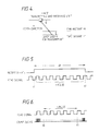
- For example, when the speed V of the ship is desired to be detected, an ultrasonic signal (having a carrier frequency "fo") is emitted downwardly in an oblique direction (at an angle θ with respect to the horizontal) by means of a transmitting-and-receiving transducer as shown in Fig. 4. A Doppler frequency shift "fd" included in echo signals reflected by theseabed will be as follows:


- A variable frequency oscillator is provided in a measuring device and is controlled so that a difference between the frequency of output signals from the oscillator and the frequency of echo signals becomes zero. The frequency of the echo signals will be obtained from the varied frequencies.
- With this method, however, the oscillator will be a complex circuit structure in which a PLL system and the like is used; there are limitations in the frequency tracking speed and in the range thereof; and it is difficult to detect the Do ppler shift frequency with high precision based on echo signals resulting from one transmission and reception of ultrasonic wave signals. Moreover, due to the limitation of the tracking speed, a tracking circuit is required for a beam formed by each of transducers and for each of liquid layers to be measured, so that a large number of parts are needed for an apparatus such as a current flow metering system using a plurality of beams and receiving echo signals from a plurality of water layers to be investigated.
- As shown in Fig. 5, this is a method to set a certain duration of time from "t0" to "t1" and to count the number of pulses of the echo signal detected within the time duration. Since frequency is expressed by the number of waves (number of pulses) in one second, the Doppler shifted frequency can be obtained in accordance with n/Δt , where thetime duration for measurement is Δt and the number of pulsescounted in the time duration is "n".
- However, in order to detect the frequency with high precision, a time duration for measurement must be set long. This increases the thickness of a layer to be investigated that corresponds to the time from a time instant "t0" to another time instant "t1" (as shown in Fig. 4). As a result, resolution in the depth direction degraded, and thus it becomes difficult to measure a Doppler shift frequency of an echo signal produced at a desired depth.
- This is a method to obtain a time Δt required for counting a certain number of pulses "n" included in an echo signal, as is opposite to the
method ② , and then to calculate an average period T (=Δt/n) per one pulse included in the echo signal and to invert the period (1/T) to obtain a Doppler shifted frequency. This method measures a time duration corresponding to n pulses included in the echo signal with count clock pulses having an extremely high repetition frequency as compared to the frequency of the echo signal so that it is possible to obtain a Doppler shifted frequency with higher precision as compared to themethod ② . - However, echo signals reflected by a water body including planktons and the like are generally very weak and do not have a good S/N ratio. As a result, there may be cases that pulses being counted are interrupted, so that a time for measurement is prolonged. Moreover, pulses having an abnormal frequency (period) may be contained in echo signals due to noise and the like, and when the abnormal pulses are counted, the time for measurement will be shortened. Accordingly, in the both cases, the accuracy for detecting a Doppler shifted frequency is degraded. Furthermore, as stated with the
method ② , there has been a problem that an echo generated at a desired depth can not be accurately derived (time "t1" in Fig. 4 changes). - As apparent from the foregoing explanation, in order to accurately detect a Doppler shifted frequency, it becomes important to meet each of the following requirements:
- 1) a Doppler shifted frequency should be detected by emitting one search signal and receiving echo signals resulting therefrom;
- 2) successive measurements for investigating multi-points without defining layers should be implemented (simplification of hardwares);
- 3) the thickness of a layer to be investigated (time duration for measurement) should be decreased to improve measurement resolution in a depth direction; and
- 4) the Doppler shift frequency should be less influenced by noise and the like.
- Various attempts have been made to provide a pulsed Doppler sonar which meets the above requirements. For example, JP61-246687A discloses a speed measuring apparatus in which a transmission pulse is formed based on an angular frequency generated by a signal generator, which angular frequency is later mixed with the reflected signals to extract a Doppler deviation component.
- US Patent 4138657 discloses a Doppler sonar which may be programmed to receive echo signals from various water masses circulating at various depths between the ship and the water bottom.
- On the other hand. in recent years, studies on applying Fourier Transformation in determining a frequency with high accuracy has been actively conducted. For example. there has been known "High Accuracy Frequency Determination Method Using FFT" by Makoto Tabei and Mitsuhiro Ueda (Journal of the Electronics Information and Communication Society, May 1987, pages 798 through 805). This frequency determination method implements Fourier transformation after multiplying data inputted in a time divisional fashion by the Hanning window and detects frequencies with high precision based on an amplit ude ratio of the maximum amplitude of signal and the signal amplitude of a frequency adjacent to the frequency of the maximum amplitude signal and from properties of a response function of the Hanning window. It is to be noted that the Hanning window is expressed by an equation (3) in page 799 of the aforementioned Journal of the Electronics Information and Communication Society and the determination of frequencies by interpolation is presented by Expression (16) in page 800 of the same.
- One object of the present invention is to provide an apparatus measuring the velocity of a moving body for measuring, with a novel method, the speed of a moving body, which is mounted on the own ship and detects the speed of own ship with respect to the water by detecting Doppler shifted frequencies generated with ultrasonic echo signals propagating in the water.
- Another object of the present invention is to provide an apparatus measuring the velocity of a moving body for measuring, with a novel method, the speed of a moving body, which is mounted on the own ship and detects the speed of the own ship with respect to the seabed or with respect to the water by detecting Doppler shifted frequencies generated in ultrasonic wave echo signals propagating in the water.
- Another object of the present invention is to provide a ship-borne apparatus measuring the velocity of a moving body for measuring, with a novel method, the velocity of a water current flow at a depth by detecting Doppler shifted frequencies generated in ultrasonic wave echo signals propagating in the water.
- Another object of the present invention is to provide a ship-borne apparatus measuring the velocity of a moving body for measuring, with a novel method, the speeds of current flows at a plurality of depths by detecting Doppler shifted frequencies generated with ultrasonic wave echo signals propagating in the water.
- Another object of the present invention is to provide an apparatus measuring the velocity of a moving body for detecting, with high precision, Doppler shifted frequencies generated with ultrasonic echo signals propagating in the water by utilizing FFT (Fast Fourier Transformation).
- Another object of the present invention is to provide an apparatus measuring the velocity of a moving body for detecting, with high precision, Doppler shifted frequencies generated in ultrasonic wave echo signals propagating in the water by utilizing FFT (Fast Fourier Transformation) and for measuring the speed of the own ship with respect to the seabed or with respect to the water based on the Doppler shifted frequencies obtained.
- Another object of the present invention is to provide an apparatus measuring the velocity of a moving body for detecting, with high precision, Doppler shifted frequencies generated in ultrasonic wave echo signals propagating in the water by utilizing FFT (Fast Fourier Transformation) and for measuring the speed of the own ship with respect to the seabed or with respect to the water based on the Doppler shifted frequencies obtained.
- Another object of the present invention is to provide an apparatus measuring the velocity of a moving body for detecting, with high precision, Doppler shifted frequencies generated in ultrasonic wave echo signals propagating in the water by utilizing FFT (Fast Fourier Transformation) and for measuring the velocity of water current flows at one or at a plurality of depths based on the Doppler shifted frequencies obtained.
- Another object of the present invention is to provide an apparatus measuring the velocity of a moving body for detecting Doppler shifted frequencies generated in ultrasonic wave echo signals propagating in the water and for measuring the speed of the own ship with respect to the water at one depth or at each of a plurality of depths based on the Doppler shifted frequencies obtained and at the same time for measuring the speed of the own ship with respect to the ground by using a navigational aid device and for detecting the velocity of current flows at one or at a plurality of depths based on the two kinds of the speeds.
- Another object of the present invention is to provide an apparatus measuring the velocity of a moving body for detecting, with high precision, Doppler shifted frequencies generated in ultrasonic echo signals propagating in the water by utilizing FFT and for measuring the speed of the own ship with respect to the water at one depth or at each of a plurality of depths based on the Doppler shifted frequencies obtained and at the same time for measuring the speed of the own ship with respect to the ground by using a navigational aid device and for detecting the velocity of currents at one or at a plurality of depths based on the two kinds of the speeds.
- Another object of the present invention is to provide an apparatus measuring the velocity of a moving body for accurately obtaining the repetition period of pulses making carrier signals of ultrasonic echoes and for detecting Doppler shifted frequencies with high precision based on the inverse value of the repetition period.
- Another object of the present invention is to provide an apparatus measuring the velocity of a moving body for accurately obtaining the repetition period of pulses making carrier signals of ultrasonic wave echoes and for detecting Doppler shifted frequencies with high precision based on the inverse value of the repetition period and for detecting the speed of the ship with respect to the water or with respect to the seabed based on the Doppler shifted frequencies obtained.
- Another object of the present invention is to provide an apparatus measuring the velocity of a moving body for accurately obtaining the repetition period of pulses making carrier signals of ultrasonic wave echoes and for detecting Doppler shifted frequencies with high precision based on the inverse value of the repetition period and for measuring the velocity of water current flows based on the Doppler shifted frequencies obtained.
- Another object of the present invention is to provide an apparatus measuring the velocity of a moving body for accurately obtaining the repetition period of pulses making carrier signals of ultrasonic wave echoes and for detecting Doppler shifted frequencies with high precision based on the inverse value of the repetition period and for measuring the speed of the ship with respect to the water or with respect to the ground based on the Doppler shifted frequencies obtained and for obtaining the velocity of current flows based on the speed of the ship with respect to the water and the speed of the ship with respect to the ground.
- Another object of the present invention is to provide an apparatus measuring the velocity of a moving body for accurately obtaining the repetition period of pulses making carrier signals of ultrasonic wave echoes and for detecting Doppler shifted frequencies with high precision based on the inverse value of the repetition period and for measuring the speed of the ship with respect to the water at one depth or at a plurality of depths based on the Doppler shifted frequencies obtained and for obtaining at the same time the speed of the own ship with respect to the ground by utilizing a navigational aid device and for detecting the velocity of current flows at one or at a plurality of depths based on the two kinds of the speeds.
- Another object of the present invention is to provide a system measuring the velocity of a moving body which comprises a first apparatus measuring the speed of a moving body for detecting, with high precision, Doppler shifted frequencies generated in ultrasonic wave echo signals propagating in the water by utilizing FFT (Fast Fourier Transformation) and for measuring the speed of the own ship with respect to the water or with respect to the ground; a second apparatus measuring the speed of a moving body for accurately obtaining the repetition period of pulses making carrier signals of ultrasonic wave echoes and for detecting Doppler shifted frequencies with high precision based on the inverse value of the repetition period and for measuring the speed of the ship with respect to the water or with respect to the seabed; and switch means for switching to select the first apparatus measuring the velocity of a moving body or the second velocity measuring apparatus.
- Another object of the present invention is to provide an apparatus measuring the speed of a moving body for detecting frequencies with high precision by averaging low S/N ratio echoes reflected by a layer in the water in the frequency axis and thus measuring the speed of water currents and for detecting the velocity of the ship with high precision.
- According to the a first aspect of the present invention there is provided an apparatus for measuring the speed of a moving body which measures the speed of a ship with respect to the water and/or the ground by detecting a Doppler shift frequency contained in ultrasonic echo signals propagating in the water, which apparatus comprises:
- phase difference detecting means for detecting a phase difference between at least one reference signal and the echo signals received; and
- computing means for implementing a Fourier transformation on phase difference data obtained by said phase difference detecting means and for computing the speed of the ship with respect to the water and/or to the ground based on the resultant Fourier spectrum; and
- A first feature of the present invention is to provide an apparatus measuring the velocity of a moving body for detecting Doppler shifted frequencies generated in ultrasonic wave echo signals propagating in the water to detect the speed of a ship, which comprises phase difference detecting means for detecting phase differences between the echo signals detected during a certain measurement time and reference signals and computing means for implementing a Fourier transformation on the phase difference data obtained by the phase difference detecting means to detect Doppler shifted frequencies based ona Fourier spectrum obtained and for computing the speed of theown ship with respect to the water or with respect to the seabed or the velocity of water current flows based on the Doppler frequency shifts obtained.
- In order to find the speed of own ship with respect to the ground or with respect to the groundt. it is required to, firstly, obtain the Doppler frequency shift in the equation (1'). The first feature of the present invention is as follows:
- There is obtained the phase θe(t) of echo signals reflected by the ground or by liquid layers in the water at a time instant "t";
- the phase is trigonometrically transformed to obtain the following signals R(t) and I(t).

- then the Doppler shift frequency is determined by multiplying the resultant transformed signals supplied in a time divisional fashion by the Hanning window, implementing the Fourier transformation thereon and applying frequency-interpolation thereon in accordance with the aforementioned "High Precision Frequency Determination Method Using FFT"; and
- the speed of own ship with respect to the ground or with respect to the water is obtained based on the Doppler frequency shift obtained.
- A second feature of the present invention is to provide an apparatus measuring the velocity of a moving body for detecting Doppler shifted frequencies generated in ultrasonic wave echo signals propagating in the water to detect the velocity of current flows or the speed of a ship or the like which comprises period detecting means for detecting the time period for each pulse of the echo signal during a given measurement time, period judging means for judging the time period as normal if the detected period is in a predetermined period range and average period computing means for computing an average period by utilizing a plurality of the time periods determined as normal by the period judging means, with the Doppler shift frequency obtained from the inverse value of the average period computed by the average period computing means.
- According to the second feature of the invention, each of the requirements 1) through 4) aforementioned can be met. At first, it is impossible to use the
method ① for tracking the frequency in order to meet the requirement 1) and it is necessary to use thepulse counting method ② or theperiod detecting method ③ therefor. With the requirement 3), it is theperiod detecting method ③ which is capable of improving detection precision in detecting Doppler shift frequency during a short measurement time. Accordingly, it will be sufficient if the other requirements 2) and 4) aforementioned are realized by theperiod detecting method ③. There is conceivable a block structure as shown in Fig. 9 as a period detecting method to meet the requirements. That is, when it is desired to count n pulses contained in an echo signal. the time to count n pulses is obtained based on a number of clock pulses counted by acounter 62 during a time period defined by a start pulse and an end pulse produced by apulse generator 63 respectively at a leading edge and a trailing edge of one pulse obtained by dividing the frequency of the input signals by means of a n-frequency-divider 61. as shown in Fig. 7. However, with this circuit configuration, there is a possibility that pulses having abnormal periods mentioned in the requirement 4) are divided by the n-frequency-divider 61. Then, there is conceivable a circuit configuration as shown in Fig. 11 as a method for assuredly detecting the period of each pulse in the echo signal successively without interruption while satisfying the requirement 2). Acounter 81 comprises a free running counter that continues to count up in response to count clock pulses. Assuming that the frequency of the count clock pulses is "fc" and the bit number of thecounter 81 is k-bit, the counter repeats to counting up the clock pulses within a range of 0 to (2k - 1) and the count output will be signals obtained by dividing the count clock pulses by 2l through 2k. Then, the Doppler shifted frequency for a water layer to be investigated is obtained by latching this count value by means of alatch circuit 82 at each leading edge of the echo signal. by successively writing the output signals of the latch circuit into different memory elements of a memory and the like at a given period while changing the address thereof and by reading the data from memory elements having addresses that correspond to the width of a layer to be investigated. in such an order from a start depth to an end depth thereof. With this circuit configuration. as shown in Fig.12, assuming that the count value latched at the leading edge of the first pulse contained in an echo signal is "x1" and a latch output resulting from the next one pulse is "x2", the time period between these two pulses of the echo signal is expressed by the following expression:
- On the other hand, the requirement 4) can be met by setting a frequency band corresponding to the period τ produced every one pulse in the echo signal and performing a judgement whether the period τ produced every one pulse is good or bad, since a frequency band for Doppler shifted frequencies can be predicted.
- Furthermore, when a desired resolution cannot be obtained in detecting the frequency from the period of one pulse, the resolution of the detected frequency can be improved by obtaining an average period from detected period values of several pulses. The time required for detecting period values for several pulses contained in the echo signal is equivalent to a width for investigation beginning at a depth. Thus, any desired measurement width can be set by adjusting the measurement time. While, with the method as described in Fig. 9 for dividing pulses contained in the echo signal by "n". it can not be said that it is detected during a desired measurement time (measurement width), since the period of pulses in the echo signal itself is unknown, and thus a time required to detect n pulses is unknown and a width for measurement is also unknown.
- Accordingly, the second feature of the present invention is that it measures the period of each pulse of the echo signal during a given time for measurement, determines whether the measured period is normal or not and then detects the Doppler shifted frequency based on a plurality of periods determined as normal in order to improve resolution in detecting the frequency.
-
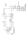
- Fig. 1 is a block diagram of one preferred embodiment of an apparatus for measuring the velocity of a moving body in accordance with the present invention;
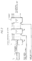
- Fig. 2 is a block diagram showing a detailed structure of the main part of the apparatus in Fig. 1;
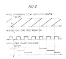
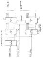
- Fig. 3 is a time chart for explaining operations of the apparatus in Fig. 1;
- Fig. 4 is a schematic view for explaining a method for measuring the speed of a ship;
- Figs. 5 and 6 are time charts for explaining operations of a pulse counting method and a period detecting method respectively used for detecting a Doppler shifted frequency in an echo signal;
- Fig. 7 is a block diagram of one preferred embodiment of an apparatus for measuring the velocity of a moving body according to the present invention;
- Fig. 8 is a block diagram showing a detailed structure of main parts of the apparatus in Fig. 7;
- Fig. 9 is a block diagram of a period detecting circuit;
- Fig. 10 is a time chart for explaining operations of the block diagram in Fig. 9;
- Fig. 11 is a block diagram of a period detecting circuit obtained by improving the period detection in Fig. 10;
- Fig. 12 is a time chart for explaining operations of the block diagram in Fig. 11;
- Fig. 13 is a block diagram of another preferred embodiment of the present invention; and
- Fig. 14 is a block diagram of still another preferred embodiment of the present invention.
- It should be noted that throughout the drawings, ones having like reference characters perform the same functions.
- Firstly,there are explained cases for measuring the speed of a ship with respect to the water or with respect to the ground. An ultrasonic transmitting-and-receiving
unit 1 radiates an ultrasonic wave pulse signal and receives echo signals generated at a depth or at the seabed. Atransmitter 2 outputs transmission electric power to be applied to the ultrasonic transmitting-and-receivingunit 1 to emit an ultrasonic pulse signal from theunit 1. A transmit/receive switch S switches to derive transmission signals or reception signals. Areceiver 3 converts the echo signals caught by the ultrasonic transmitting-and-receivingunit 1 to signals in a desired frequency band to limit the frequency band and detects zero crosses of the received echo signals to output the received echo signals as zero cross signals in a rectangular waveform. Anoscillator 4 produces reference clock signals. Aphase difference detector 6 detects phase differences between the phase of zero cross signals supplied from thereceiver 3 and that of the reference signals supplied from theoscillator 4. Amemory 7 latches the phase difference data outputted from thephase difference detector 6 in response to sampling clock pulses supplied from theoscillator 4. A computing andprocessing unit 8 implements trigonometric function transformation on the sampled phase difference data supplied from thememory 7, detects Doppler shift frequencies of echo signals generated at a depth or at the seabed and computes the speed of own ship with respect to the water or with respect to the ground based on detected Doppler frequency shifts in accordance with the equation (1'). - Fig. 2 shows an example of a detailed construction of the
oscillator 4 through thememory 7, wherein thephase difference detector 6 is comprised of a k-bitfree running counter 6A and a k-bit flip-flop circuit 6B, and thememory 7 is comprised of a k-bit flip-flop circuit. - Referring now to Figs. 1, 2 and 3, operation of the preferred embodiment of the present invention will be explained.
- When an ultrasonic pulse signal is transmitted from the transmitting-and-receiving
unit 1, and echo signals resulting therefrom are received by theunit 1 and are supplied to thereceiver 3 through the transmit/receive selector S, zero cross signals corresponding to the echo signals are generated by thereceiver 3 and are supplied to thephase difference detector 6, as shown in Fig. 3(B). While, the k-bit counter 6A repeats counting up operation within a range of 0 through (2k - 1) as shown in Fig. 3A, and an output from the k-bit counter 6A will be the phase of the signals obtained by dividing the reference clock pulses by 2k and is expressed by a step of 2π/2k. The k-bit flip-flop circuit 6B of thephase difference detector 6 latches the signal outputted from the k-bit counter 6A every one period of the zero cross signal, so that a latch signal outputted from thephase difference detector 6 will be a phase difference of signals between signals obtained by dividing the reference clock pulses by 2k and the zero cross signals as shown in Fig. 3C. The phase difference signal sent out of thephase difference detector 6 is written into and stored in thememory 7. - It is assumed that the phase θp(t) of the signal obtained by dividing the reference clock pulses by 2k is expressed by the following equation:


phase difference detector 6 will be expressed by the following expression:
- When those values are inputted to the computing and
processing unit 8, theunit 8 detects Doppler shift frequencies of echo signals generated at a depth or at the seabed in accordance with the aforementioned frequency determination method using FFT and computes the speed of own ship with respect to the water or with respect to the ground based on thedetected Doppler frequency shifts in accordance with the equation (1'). - In this case, if a start depth and a time width for measurement have been inputted to the computing and
processing unit 8 in advance, the aforementioned phase difference data Δθw(t) and Δθg(t) corresponding to those input data are obtained, and trigonometric function transformation is implemented on those data within the measurement time so that data are successively produced in a time divisional fashion. The series of data time-sequentially produced are Fourier-transformed and a frequency interpolation is implemented after multiplying the series of data by the Hanning window to determine the frequency. - Next, the Doppler frequency shift can be computed in accordance with an equation:

- The computing and
processing unit 8 also computes the speed of a water current at any desired depth in accordance with an equation:
- Referring now to Figs. 7 and 8, there will be explained another preferred embodiment of an apparatus for measuring the velocity of moving bodies in accordance with the present invention.
- An ultrasonic transmitting-and-receiving
unit 1 radiates an ultrasonic pulse signal and receives echo signals resulting therefrom. Atransmitter 2 outputs transmission electric power to be applied to the ultrasonic transmitting-and-receivingunit 1. Areceiver 3 amplifies received echo signals supplied from the transmitting-and-receivingunit 1. A transmit/receive switch S switches to derive transmission signals or reception signals. Aperiod detecting unit 16 detects a period for each pulse of the echo signal outputted from thereceiver 3. A pulsenumber counting unit 5 counts the number of the pulses in the echo signal. Amemory 17 stores the period and the number of pulses outputted from theperiod detector 16 and the pulsenumber counting unit 5. Anoscillator 4 outputs count clock pulses and sampling clock pulses to theperiod detector 16 and thememory 17 respectively. Acomputing unit 18 finds the period based on the data read out from thememory 17, with a measurement starting depth (time "t0" in Fig. 4) and a measurement width (time "t0" or "t1" in Fig. 4) set into thecomputing unit 18 to compute a Doppler frequency shift. Thecomputing unit 18 is provided with a determiningpart 18A for determining whether the period found is normal or not. - Fig. 8 shows a detailed circuit diagram of the
period detector 16, the pulsenumber counting unit 5 and thememory 17. Theperiod detecting unit 16 is comprised of a k-bit counter 16A and a k-bit flip-flop circuit 16B. The pulsenumber counting unit 5 is comprised of an ℓ-bit counter. Thememory 17 is comprised of a k-bit flip-flop circuit 17A and an ℓ-bit flip-flop circuit 17B. - Referring now to Figs. 7 and 8, operation of the preferred embodiment of the present invention described therein will be explained.
- When an ultrasonic signal is emitted from the transmitting-and-receiving
unit 1 and echo signals resulting therefrom are detected by theunit 1 and an echo signal is outputted from the receiver, the period of each pulse of the echo signal is detected by theperiod detector 16 based on the counting clocks and the number of pulses of the echo signal is counted by the pulsenumber counting unit 5. These detected period and number of pulses are taken into thememory 17 based on the sampling clocks, sent out to thecomputing unit 18 and the following sampled outputs are inputted to the computing unit 18:Sampling Output of the Oscillator 4: Sampling Output of the Pulse Number Counting Unit 5: xi-2 yi-2 xi-1 yi-1 xi yi xi+1 yi+1 xi+2 yi+2 : : xj-2 yj-2 xj-1 yj-1 xj yj xj+1 yj+1 : : - With the series of the data above, assuming that xi and yi are data at a time that corresponds to the measurement start depth (corresponding to time "t0"), and xj and yj are data at a time that corresponds to the measurement end depth (corresponding to time "ti"), xi through xj from the
period detector 16 and yi through yj from the pulsenumber counting unit 5 will be the data within the measurement width (measurement time). Accordingly, the time width Δxm of the pulses and the number of counted pulses Δym within the above sampling period can be expressed by the following expressions:

computing unit 18. - With apparatuses of this kind, the speed detecting range is normally set by specification, so that a frequency band width for echo signals with its frequency being Doppler shifted can be determined. Thus, a range of the period of pulse can be set from the frequency band width. Moreover, since a speed of a ship and the like is rarely changed adruptly, so that a certain range can be set for the fluctuation of the speed of a ship i.e., for fluctuationable amounts of the Doppler shift frequency and the period. From that, by having set a range of normal periodrange Δτmin ∼ Δτmax into the
computing unit 18, the detected period can be determined as resulting from a normal pulse or not by judging whether an instantaneous period Δτ (= Δxm/ ym) for one pulse of the echo signal obtained in accordance with the equation (7) satisfies the following Expression (9).
- In this way, the above judgment is carried out for each one pulse and the sums X' and Y' of respective Δxm and Δym of normal periods are respectively obtained.

- After that, an average Doppler shift frequency f can be obtained based on the normal periods in accordance with the following Expression (11):

- It is to be noted that with Doppler sonars and water current flow meters, mainly a three-beam or a four-beam system is adopted to reduce influences caused by pitch, roll or yaw of a ship. With the arrangement shown in Fig. 7, when the number of the beams is increased, only the
period detector 16 and the pulsenumber counting unit 5 need to be provided for each beam, while with the frequency tracking method thesedetectors 16 and theunit 5 must be provided for each beam and each measurement layer. Thus, according to the present invention, the hardwares can be simplified and the number of parts can be decreased. - Referring now to Fig. 13, another embodiment of the present invention will be explained.
- This embodiment comprises a first speed detector for moving bodies for measuring the speed of a ship with respect to the water or with respect to the ground or the velocity of water currents using FFT as shown in Fig. 1, a second speed detector for moving bodies for detecting the speed of own ship with respect to the water or with respect to the seabed or the speed of water currents by obtaining the period of each pulse of a carrier signal contained in an echo signal as shown in Fig. 7 and a switching means, and selects as desired to operate the first or the second speed detector for moving bodies.
- The first speed detector for moving bodies shown in Fig. 1 can be used even in an environment where S/N ratio is not so good and is capable of measuring the speed of own ship with respect to the water or with respect to the ground at a deep depth in the water. It needs a certain length of measurement time to detect a Doppler shift frequency. On the other hand, although it is not appropriate to use the second speed detector for moving bodies shown in Fig. 7 in an environment where S/N ratio is not so good, since it is influenced by noises, it has no restrictions in terms of the time for detecting the Doppler shift frequency. Thus, it fits in measuring the speed of the ship with respect to the water or with respect to the ground or the speed of a water current flow in a shallow water. The selective use of the first or the second speed detector for moving bodies according to an environment enables to more accurately measure the speed of a ship with respect to the water or with respect to the ground or the speed of a water current flow regardless of the depth.
- A phase detector/
period detector 26 is comprised of a k-bitfree running counter flop circuit memory 17 is comprised of k-bit flip-flop circuits 17A and 17B as shown in Fig 8. When the first speed detector for moving bodies is selected, a computing andprocessing unit 28 detects a Doppler shift frequency of an echo signal generated at a depth or at the seabed after implementing trigonometric function transformation on sampled phase difference data supplied from the flip-flop circuit 17A of thememory 17 as shown in Expression (2) and then computes the speed of own ship with respect to the water or with the ground based on the detected Doppler frequency shift in accordance with the equation (1') and further computes the speed of water current flows based on those speeds of the ship. Moreover, when the second speed detector for moving bodies is selected, thecomputing unit 28 finds the period based on data read out from thememory 17, computes a Doppler shift frequency, judges whether the period found is normal or not and computes the speed of the ship with respect to the water or with respect to the ground or the velocity of a water current. Aswitch 10 selects and operates either the first or the second speed detector for moving bodies. - Firstly, there will be explained a case in which the first speed detector for moving bodies which uses FFT is selected by means of the
switch 10 to obtain the speed of own ship with respect to the water or with respect to the ground or the speed of a water current. - When an ultrasonic pulse signal is transmitted from the transmitting-and-receiving
unit 1, and echo signals resulting therefrom are caught by theunit 1 and are inputted to thereceiver 3 through the transmit/receive switch S, zero cross signals that correspond to the echo signals are generated in thereceiver 3 and outputted as shown in Fig. 3B and are inputted to the phase difference/period detector 26. In this case, the phase difference/period detector 26 operates so as to detect a phase difference. On the other hand, the k-bit counters bit counters flop circuits detector 26 latch the output signals from the k-bit counters detector 26 will be signals representing phase differences between the signals obtained by dividing the reference clocks by 2k and the zero cross signal, as shown in Fig. 3C. The phase difference signals sent out of the phase difference/period detector 26 are written into and stored in thememory 17. When quantized phase difference values Δθw(t) and Δθg(t) of the echo signals generated in the water or at the seabed with respect to the reference clock signals are inputted from thememory 17 to the computing andprocessing unit 28, the computing andprocessing unit 28 detects a Doppler shift frequency of the echo signal generated at a depth or at the seabed in accordance with the aforementioned frequency determination method using FFT and computes the speed of own ship with respect to the water or with respect to the ground based on the resultant Doppler frequency shift in accordance with the aforementioned Expression (1'). Moreover, it computes the speed of the water current based on those speeds with respect to the water or with respect to the ground. These operations are the same with the one performed with the embodiment shown in Fig. 1. - Next, there will be explained a case in which the
switch 10 selects the second speed detector for moving bodies to measure the period of each pulse of the carrier signal contained in the echo signal to detect the Doppler shift frequency to obtain the speed of own ship with respect to the water or with respect to the ground or the speed of water currents. - In this case, the phase difference/
period detector 26 detects the period of the signal. Thecomputing unit 28 also finds the period of signals based on the data read out of thememory 17 and computes the Doppler shift frequency. When an ultrasonic signal is emitted from the transmitting-and-receivingunit 1, resultant echo signals are caught by theunit 1, and the echo signals are outputted from thereceiver 3, the period of each pulse of the echo signal is detected by the phase difference/period detector 26 based on the count clocks and the number of pulses of the echo signal is counted by the pulsenumber counting unit 5. These detected period and number of pulses are taken into thememory 17 in response to sampling clocks and are sent out to thecomputing unit 28. Thecomputing unit 28 computes the speed of own ship or of the water current based on the Doppler shift frequency detected. These operations are the same as the ones with the embodiment shown in Fig. 8. - In Fig. 14, a
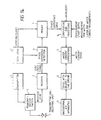
navigation system 11 is comprised of, for example, a Loran receiver, measures the position of a point on the Earth, generates signals representing, for example, the longitude and latitude of the point and transmits the signals to acomputing unit 12 for the ship's speed with respect to the ground. Thecomputing unit 12 computes the speed of own ship with respect to the ground based on distances between at least two points and times necessary for the ship to travel between the two points and sends it to a watercurrent computing unit 13. In Fig. 14, the construction of the other parts than thenavigation system 11, thecomputing unit 12 for the ship's speed with respect to the ground and the watercurrent computing unit 13 is the same as the one with the embodiment shown in Fig. 1. The computing andprocessing unit 8 supplies the speed of a ship with respect to the water at a depth or at a plurality of depths to the water current computing unit. The watercurrent computing unit 13 computes and finds the speeds of water currents at one depth or at the plurality of depths based on the inputted ship speeds with respect to the ground and with respect to the water. - Although a navigational aid apparatus comprising a loran receiver is used in the embodiment shown in Fig. 14, a GPS receiver (Global Positioning System) can also be used to achieve the same object. The GPS receiver is capable of supplying a signal representing the speed of own ship with respect to the ground directly to the water
current computing unit 13, so that in this case, thecomputing unit 12 for the ship's speed with respect to the ground becomes unnecessary. - It should be noted that in the same way as the embodiment shown in Fig. 14, if the
navigation system 11, thecomputing unit 12 for the ship's speed with respect to the ground and the watercurrent computing unit 13 are added to the arrangement of the embodiment shown in Fig. 7, and the watercurrent computing unit 13 is supplied with the speed of ship with respect to the water from thecomputing unit 18 and also with the speed of ship with respect to the ground from thecomputing unit 12 for the ship's speed with respect to the ground, there can be measured the velocity of water currents at one depth or at a plurality of depths. Moreover, instead of using thenavigation system 11 and thecomputing unit 12 for obtaining the ship's speed with respect to the ground, it is also possible to use a GPS receiver to directly sending the signal representing the speed of own ship with respect to the ground to the watercurrent computing unit 13, so that the velocity of water currents are obtained. - It should be noted that in the same way as the embodiment shown in Fig. 14, if the
navigation system 11, thecomputing unit 12 for the ship's speed with respect to the ground and the watercurrent computing unit 13 are added to the arrangement of the embodiment shown in Fig. 13, and the watercurrent computing unit 13 is supplied with the speed of ship with respect to the water from thecomputing unit 28 and also with the speed of ship with respect to the ground from thecomputing unit 12 for the ship's speed with respect to the ground, there can be measured the velocity of water currents at one depth or at a plurality of depths, even when either one of the first or the second speed detector for moving bodies is selected. Moreover, instead of using thenavigationsystem 11 and thecomputing unit 12 for obtaining the ship's speed with respect to the ground, it is also possible to use a GPS receiver to directly sending the signal representing the speed of own ship with respect to the ground to the watercurrent computing unit 13, so that the velocity of water currents are obtained. - There will be explained a feature of the present invention for further improving the performance of the embodiments employing the method for determining the Doppler shift frequency using FFT described in Figs. 1, 13 or 14.
- With regard to the method for determining the Doppler shift frequency using FFT employed in the embodiments described in Figs. 1, 13 or 14, the maximum amplitude needs to be detected from the spectrum of detected data obtained by Fourier transformation. Although spectrum of white noise shows, theoretically, a constant value in any frequency component, in reality, the signals obtained by Fourier-transforming the time series data of the noise do not necessarily show a constant value and the value of the data varies within a certain range. If an amplitude value caused by dispersion of the spectrum component due to noise becomes larger than the amplitude of the signal when a time series data with low S/N ratio is Fourier-transformed, a large error is generated in a detected frequency. Although the maximum amplitude in the signal frequency may be easily detected if a plurality of detected signals are averaged on a frequency axis to avoid this problem, the average processing cannot be implemented on the frequency axis as it is because the Doppler shift frequency changes every time when transmitted and received due to a fluctuation of a ship even if it sails at a constant speed (because constancy cannot be assumed with the signal frequency). In fact, echo signals (with respect to the water) reflected by the seabed or a water body such as planktons and the like are very weak and a signal having high S/N ratio cannot be expected. Thus. it will be a problem to measure the frequency of signals having low S/N ratio with high precision.
- There will be explained a method for averaging echo signals reflected at a depth in the water (not by the seabed) having low S/N ratio on the frequency axis.
- To find the speed of a ship with respect to the water/ground is to find the Doppler frequency shift in the expression (1'). When the phase of echo signals reflected by the ground or by a body of water at a time instant "t" is expressed as θe(t), signals R(t) and I(t) which are obtained by implementing a trigonometric function transformation on the phase are as follows:


- On the other hand, the speed of a water current flow is obtained by taking a difference between the ship's speed with respect to the ground and the ship's speed with respect to the water. Expressing the ship's speed with respect to the ground as "Vg" and the ship's speed with respect to the water as "Vw", the speed of the water current flow "Vc" will be


- Next, a method how to implement the above will be considered. Normally, as a technique for quantizing to obtain a time series data which are necessary for Fourier transformation, an A/D converter is used. However, it is difficult to obtain the Doppler spectrum due to the water current speed component simply just by quantizing the amplitude of the time series data according to this technique. Then, the following technique comes up to be used.
- The frequency can be given by time differentiating the phase. Expressing that the phases of the echo signals reflected by the ground and of the echo signals reflected by a body of water at a time instant "t" as θg(t) and θw(t) respectively, the phase of the water current is expressed as θc(t) with the initial phase expressed as θco. When it is trigonometric-function-transformed, it becomes as follows:

- A water current measurement layer and a start depth and a time width for measuring the speed of own ship with respect to the ground are inputted beforehand when the water current speed is desired to be measured. The aforementioned phase difference data Δθw(t) and Δθ g(t) that correspond to these set data can be found, and the phase difference qu antized value by the current Δθc(t) can be obtained by implementing subtraction on those quantized phase difference values of Δθw(t) and Δθg(t) resulting from echoe signals reflected by a body of water or by the ground as shown by the following expression:

- Although the present invention has been described in detail as described above and in connection with the several embodiments, it is understood that to those skilled in the art, various other embodiments and modifications of the embodiments described above can be easily created.
- As described above, the present invention is. as a first feature thereof, capable of producing the following effects by applying the high precision frequency determination method using Fourier transformation:
- the speed can be detected in real time;
- a frequency can be detected with high precision even when the thickness of a measurement layer (measurement time width) is small and resolution in the depth direction can be improved: and
- accuracy in detecting a frequency (or speed) from signals having low S/N ratio can be evaluated quantitively using equations.
- Furthermore, the use of the phase difference detecting method as pre-processing prior to the Fourier transformation allows to obtain the following advantages:
- phase data of a Doppler shift frequency due to a water current can be quantized directly from a phase difference between the reference clocks and echo signals reflected by the ground or by a water body and spectra can be averaged;
- the phase data can be obtained from zero cross signals in the same manner as the conventional frequency detecting method and frequency tracking method using zero cross signals, and the performance of the conventional systems can be improved; and
- Although the amplitude information is normalized as compared to a typical A/D conversion method, a dynamic range can be always kept in an ideal condition and analog processing can be simplified since a zero cross detector is used.
- Further, the present invention is, as a second feature thereof, capable of improving detecting accuracy by detecting the period per each pulse of the echo signal and taking only normal ones among those periods found to remove abnormal period. The present invention is further capable of improving the detecting accuracy by obtaining the Doppler shift frequency from a plurality of the normal periods.
said computing means implements a trigonometric transformation on said data, and multiplies the resultant transformed data by the Hanning window, before determining said speed on the basis of said Fourier spectrum.
Claims (8)
- An apparatus for measuring the speed of a moving body which measures the speed of a ship with respect to the water and/or the ground by detecting a Doppler shift frequency (fd) contained in ultrasonic echo signals propagating in the water, which apparatus comprises:phase difference detecting means (6) for detecting a phase difference between at least one reference signal and the echo signals received; and computing means (8) for implementing a Fourier transformation on phase difference data obtained by said phase difference detecting means and for computing the speed of the ship with respect to the water and/or to the ground based on the resultant Fourier spectrum; andcharacterised in that:
said computing means (8) implements a trigonometric transformation on said data, and multiplies the resultant transformed data by the Hanning window, before determining said speed on the basis of said Fourier spectrum. - An apparatus according to claim 1, which further measures the velocity of a water current flow at one or more depths, said apparatus further comprising:means (8,12) for measuring the speed of the ship with respect to the ground;means (8,13) for computing the velocity of said water current flow based on the speed of the ship with respect to the ground and the speed of the ship with respect to the water.
- An apparatus according to claim 2, wherein said echo signals are generated at the sea bed and at said one or more depths, and said computing means (8) computes the velocity of the water current flow at said one or more depths based on the resultant Fourier spectra.
- An apparatus according to any preceding claim wherein the phase difference detecting means (6) detects phase differences between the echo signals and reference clock signals.
- A system for measuring the speed of a moving body which measures the velocity of a water current by detecting a Doppler shift frequency generated with ultrasonic echo signals propagating in the water, said system comprising:first apparatus according to claim 3;second apparatus comprising:period detecting means (16) for detecting the period for each pulse in the echo signals during a given measurement time;period judging means (18A) for determining whether the period detected by said period detecting means (16) is in a normal period range;average period computing means (18) for computing an average period from a plurality of periods which are judged as normal by said period judging means; andmeans (18) for obtaining a Doppler shift frequency from the inverse value of the average period obtained by said average period computing means;ship's speed computing means for computing the speed of the ship with respect to the ground and the speed of the ship with respect to the water based on said Doppler shift frequency (fd); andwater current velocity computing means (18) for computing the velocity of water current at the depth at which the echo signals are generated based on the speed of the ship with respect to the ground and the speed of the ship with respect to the water; andswitching means for switching to select the first apparatus for measuring the speed of a moving body, or the second apparatus for measuring the speed of a moving body.
- An apparatus for measuring the speed of a moving body which detects the speed of a ship with respect to the water, the speed of the ship with respect to the ground, and detects the velocity of a water current based on these speeds of the ship, which apparatus comprises:first apparatus according to claim 2;second apparatus comprising:period detecting means (16) for detecting the period for each pulse in the echo signals during the given measurement time;period judging means (18A) for determining whether the period detected by said period detecting means (16) is in a normal period range;average period computing means (18) for computing an average period from a plurality of periods which are judged as normal by said period judging means; andmeans (18) for obtaining a Doppler shift frequency from the inverse value of the average period obtained by said average period computing means;ship's speed computing means for computing the speed of the ship with respect to the ground and the speed of the ship with respect to the water based on said Doppler shift frequency(fd); andwater current velocity computing means (18) for computing the velocity of water current at the depth at which the echo signals are generated based on the speed of the ship with respect to the ground and the speed of the ship with respect to the water; andswitching means for switching to select the first apparatus for measuring the speed of a moving body or the second apparatus for measuring the speed of a moving body.
- An apparatus according to claim 2 or 6, wherein the means for measuring the speed of the ship with respect to the ground comprises a GPS receiver (Global Positioning System receiver).
- An apparatus according to claim 2 or 6, wherein said means for measuring the speed of the ship with respect to the ground comprises a means (11) for measuring the position of at least two points on the earth at a time required to travel between these two points and for obtaining the speed of a ship with respect to the ground based on the resultant data.
Priority Applications (1)
| Application Number | Priority Date | Filing Date | Title |
|---|---|---|---|
| EP95119935A EP0708343B1 (en) | 1990-03-26 | 1991-03-26 | Apparatus for measuring the velocity of a moving body |
Applications Claiming Priority (3)
| Application Number | Priority Date | Filing Date | Title |
|---|---|---|---|
| JP76436/90 | 1990-03-26 | ||
| JP7643690 | 1990-03-26 | ||
| PCT/JP1991/000384 WO1991014953A1 (en) | 1990-03-26 | 1991-03-26 | Device for measuring speed of moving body |
Related Child Applications (2)
| Application Number | Title | Priority Date | Filing Date |
|---|---|---|---|
| EP95119935A Division EP0708343B1 (en) | 1990-03-26 | 1991-03-26 | Apparatus for measuring the velocity of a moving body |
| EP95119935.5 Division-Into | 1995-12-18 |
Publications (3)
| Publication Number | Publication Date |
|---|---|
| EP0481083A1 EP0481083A1 (en) | 1992-04-22 |
| EP0481083A4 EP0481083A4 (en) | 1992-06-03 |
| EP0481083B1 true EP0481083B1 (en) | 1997-05-07 |
Family
ID=13605101
Family Applications (2)
| Application Number | Title | Priority Date | Filing Date |
|---|---|---|---|
| EP91905890A Expired - Lifetime EP0481083B1 (en) | 1990-03-26 | 1991-03-26 | Device for measuring speed of moving body |
| EP95119935A Expired - Lifetime EP0708343B1 (en) | 1990-03-26 | 1991-03-26 | Apparatus for measuring the velocity of a moving body |
Family Applications After (1)
| Application Number | Title | Priority Date | Filing Date |
|---|---|---|---|
| EP95119935A Expired - Lifetime EP0708343B1 (en) | 1990-03-26 | 1991-03-26 | Apparatus for measuring the velocity of a moving body |
Country Status (6)
| Country | Link |
|---|---|
| US (1) | US5224075A (en) |
| EP (2) | EP0481083B1 (en) |
| KR (1) | KR100195576B1 (en) |
| ES (2) | ES2102396T3 (en) |
| NO (1) | NO305776B1 (en) |
| WO (1) | WO1991014953A1 (en) |
Families Citing this family (21)
| Publication number | Priority date | Publication date | Assignee | Title |
|---|---|---|---|---|
| KR960001777A (en) * | 1994-06-01 | 1996-01-25 | 제임스 디. 튜턴 | Frequency Domain Processing Method of Doppler Signal for Vehicle Surveillance System |
| US6111523A (en) | 1995-11-20 | 2000-08-29 | American Traffic Systems, Inc. | Method and apparatus for photographing traffic in an intersection |
| US5948038A (en) | 1996-07-31 | 1999-09-07 | American Traffic Systems, Inc. | Traffic violation processing system |
| CH690660A5 (en) | 1996-09-23 | 2000-11-30 | Unitron Electronics Ag | Speed Meter for objects of various kinds. |
| US7109920B2 (en) * | 2003-07-16 | 2006-09-19 | General Electric Company | Moving platform position determination system and method |
| US7123544B1 (en) | 2004-05-24 | 2006-10-17 | The United States Of America As Represented By The Secretary Of The Navy | Assembly and method for determining speed of a supercavitating underwater vehicle |
| JP2006337025A (en) * | 2005-05-31 | 2006-12-14 | Hitachi Ltd | Absolute velocity measuring device |
| JP4828295B2 (en) * | 2006-04-26 | 2011-11-30 | 古野電気株式会社 | Doppler measuring instrument and tide meter |
| JP5279990B2 (en) * | 2006-06-13 | 2013-09-04 | 古野電気株式会社 | Radar equipment |
| JP2010286354A (en) * | 2009-06-11 | 2010-12-24 | Furuno Electric Co Ltd | Device for estimation of doppler frequency, device for capturing and tracking of positioning signal, positioning device, and method of measuring doppler frequency |
| RU2467350C2 (en) * | 2009-06-15 | 2012-11-20 | Федеральное государственное казенное военное образовательное учреждение высшего профессионального образования "Военный учебно-научный центр Военно-морского флота "Военно-морская академия имени Адмирала Флота Советского союза Н.Г.Кузнецова" | Method and device of signal detection with alternating doppler effect present |
| KR101105898B1 (en) * | 2010-04-07 | 2012-01-17 | 광운대학교 산학협력단 | Apparatus and method for estimating velocity for mobile equipment |
| TWI400444B (en) * | 2010-08-13 | 2013-07-01 | Tatung Co | Ultrasonic phase-shift detection device |
| DE102010062235A1 (en) | 2010-12-01 | 2012-06-06 | Robert Bosch Gmbh | Driver assistance system for detecting an object in a vehicle environment |
| JP6039918B2 (en) * | 2012-05-22 | 2016-12-07 | 株式会社鷺宮製作所 | Test apparatus and test apparatus control method |
| KR101580427B1 (en) | 2015-01-29 | 2015-12-28 | 한국해양대학교 산학협력단 | Doppler Frequency Estimation and receiving method for Time-varying Underwater Acoustic Communication Channel |
| JP6441740B2 (en) * | 2015-05-25 | 2018-12-19 | 古野電気株式会社 | Doppler shift frequency measuring device, water velocity meter, and tidal current meter |
| CN108351409B (en) * | 2015-09-16 | 2022-03-01 | 古野电气株式会社 | Ship speed meter and ship speed acquisition method |
| KR101885065B1 (en) * | 2017-11-06 | 2018-08-03 | 대한민국 | Method, Apparatus and Computer Program for estimating the speed of a vehicle passing through a horizontal-grooved road using acoustic analysis |
| CN109541605A (en) * | 2018-11-13 | 2019-03-29 | 西北工业大学 | A method of single-frequency sound signal tranmitting frequency is reduced to improve target identification ability |
| JP2023146546A (en) * | 2022-03-29 | 2023-10-12 | 古野電気株式会社 | Ship speed measuring device and ship speed measuring method |
Family Cites Families (10)
| Publication number | Priority date | Publication date | Assignee | Title |
|---|---|---|---|---|
| JPS5018397B1 (en) * | 1970-08-28 | 1975-06-28 | ||
| JPS50129063A (en) * | 1974-03-29 | 1975-10-11 | ||
| FR2316602A1 (en) * | 1975-07-01 | 1977-01-28 | Thomson Csf | SYSTEM FOR MEASURING THE SPEED AND CURRENT DIRECTION OF A FLUID MASS |
| US4069468A (en) * | 1976-09-24 | 1978-01-17 | Raytheon Company | Doppler spectral measurement |
| US4138657A (en) * | 1977-10-25 | 1979-02-06 | Western Geophysical Co. Of America | Shipboard apparatus for measuring ocean currents |
| JPS61246687A (en) * | 1985-04-24 | 1986-11-01 | Japan Radio Co Ltd | Speed measuring apparatus |
| JPS6282381A (en) * | 1985-10-07 | 1987-04-15 | Nec Corp | Sonar device |
| JPS62294988A (en) * | 1986-06-16 | 1987-12-22 | Furuno Electric Co Ltd | Moving speed measuring apparatus for moving target |
| JPH0715484B2 (en) * | 1986-11-06 | 1995-02-22 | 古野電気株式会社 | Tidal current measuring device |
| US4942558A (en) * | 1988-03-31 | 1990-07-17 | Micro-Trak Systems, Inc. | Ultrasonic velocity sensor |
-
1991
- 1991-03-26 EP EP91905890A patent/EP0481083B1/en not_active Expired - Lifetime
- 1991-03-26 ES ES91905890T patent/ES2102396T3/en not_active Expired - Lifetime
- 1991-03-26 KR KR1019910701691A patent/KR100195576B1/en not_active IP Right Cessation
- 1991-03-26 ES ES95119935T patent/ES2146703T3/en not_active Expired - Lifetime
- 1991-03-26 US US07/775,986 patent/US5224075A/en not_active Expired - Lifetime
- 1991-03-26 EP EP95119935A patent/EP0708343B1/en not_active Expired - Lifetime
- 1991-03-26 WO PCT/JP1991/000384 patent/WO1991014953A1/en active IP Right Grant
- 1991-11-25 NO NO914616A patent/NO305776B1/en unknown
Non-Patent Citations (2)
| Title |
|---|
| Journal of the Electronics Information and Communication Society, May 1987, pages 798-805, Makoto Tabei and Mitsuhiro Ueda. * |
| Merrill I. Skolnik, "Introduction to Radar Systems", 2nd Edition, McGraw-Hill Book Co., pages 384-385. * |
Also Published As
| Publication number | Publication date |
|---|---|
| KR100195576B1 (en) | 1999-06-15 |
| EP0481083A1 (en) | 1992-04-22 |
| KR920701836A (en) | 1992-08-12 |
| EP0708343A2 (en) | 1996-04-24 |
| NO914616D0 (en) | 1991-11-25 |
| NO305776B1 (en) | 1999-07-19 |
| NO914616L (en) | 1991-11-25 |
| EP0708343B1 (en) | 2000-05-17 |
| EP0708343A3 (en) | 1996-05-29 |
| WO1991014953A1 (en) | 1991-10-03 |
| ES2146703T3 (en) | 2000-08-16 |
| US5224075A (en) | 1993-06-29 |
| ES2102396T3 (en) | 1997-08-01 |
| EP0481083A4 (en) | 1992-06-03 |
Similar Documents
| Publication | Publication Date | Title |
|---|---|---|
| EP0481083B1 (en) | Device for measuring speed of moving body | |
| USRE43090E1 (en) | Acoustic Doppler channel flow measurement system | |
| US5208785A (en) | Broadband acoustic doppler current profiler | |
| EP0010974A1 (en) | Velocity measuring correlation sonar apparatus | |
| JP2695989B2 (en) | Speed measurement system and topler sonar system and sonar | |
| US4635240A (en) | Sonar navigation system | |
| Ahearn et al. | Tests of remote skywave measurement of ocean surface conditions | |
| US20130235699A1 (en) | System and method of range estimation | |
| Sanford et al. | An acoustic Doppler and electromagnetic velocity profiler | |
| US6262942B1 (en) | Turbulence-resolving coherent acoustic sediment flux probe device and method for using | |
| US4176338A (en) | High resolution acoustic navigation system | |
| Boltryk et al. | An ultrasonic transducer array for velocity measurement in underwater vehicles | |
| Watson et al. | A new high accuracy super-short baseline (SSBL) system | |
| US6704246B1 (en) | Sound-ranging system with submarine buoy | |
| JP3028376B2 (en) | Moving object speed detector | |
| US6229761B1 (en) | Estimating ship velocity through the water and over the ground | |
| Rowe et al. | High resolution current profiler | |
| Dickey Jr et al. | Implementation and testing of a deepwater correlation velocity sonar | |
| Jorgensen et al. | Doppler sonar applied to precision underwater navigation | |
| RU2770564C1 (en) | Hydroacoustic complex for detecting a moving underwater sound source and measuring its coordinates | |
| gu Lee | Depth estimation of an underwater target using DIFAR sonobuoy | |
| JP2837484B2 (en) | Doppler speed detector | |
| JPS59230165A (en) | Measuring method of current speed and current direction by ultrasonic current and direction meter | |
| Hole et al. | IEEE zyxwvutsrqponmlkjihgfedcb | |
| Liu et al. | Velocity measurement by dural time interval pulse-to-pulse coherent Doppler sonar |
Legal Events
| Date | Code | Title | Description |
|---|---|---|---|
| PUAI | Public reference made under article 153(3) epc to a published international application that has entered the european phase |
Free format text: ORIGINAL CODE: 0009012 |
|
| 17P | Request for examination filed |
Effective date: 19911122 |
|
| AK | Designated contracting states |
Kind code of ref document: A1 Designated state(s): ES |
|
| A4 | Supplementary search report drawn up and despatched |
Effective date: 19920413 |
|
| AK | Designated contracting states |
Kind code of ref document: A4 Designated state(s): ES |
|
| 17Q | First examination report despatched |
Effective date: 19940215 |
|
| GRAG | Despatch of communication of intention to grant |
Free format text: ORIGINAL CODE: EPIDOS AGRA |
|
| GRAH | Despatch of communication of intention to grant a patent |
Free format text: ORIGINAL CODE: EPIDOS IGRA |
|
| GRAH | Despatch of communication of intention to grant a patent |
Free format text: ORIGINAL CODE: EPIDOS IGRA |
|
| GRAA | (expected) grant |
Free format text: ORIGINAL CODE: 0009210 |
|
| AK | Designated contracting states |
Kind code of ref document: B1 Designated state(s): ES |
|
| DX | Miscellaneous (deleted) | ||
| REG | Reference to a national code |
Ref country code: ES Ref legal event code: FG2A Ref document number: 2102396 Country of ref document: ES Kind code of ref document: T3 |
|
| PLBE | No opposition filed within time limit |
Free format text: ORIGINAL CODE: 0009261 |
|
| STAA | Information on the status of an ep patent application or granted ep patent |
Free format text: STATUS: NO OPPOSITION FILED WITHIN TIME LIMIT |
|
| 26N | No opposition filed | ||
| PGFP | Annual fee paid to national office [announced via postgrant information from national office to epo] |
Ref country code: ES Payment date: 20050425 Year of fee payment: 15 |
|
| PG25 | Lapsed in a contracting state [announced via postgrant information from national office to epo] |
Ref country code: ES Free format text: LAPSE BECAUSE OF NON-PAYMENT OF DUE FEES Effective date: 20060327 |
|
| REG | Reference to a national code |
Ref country code: ES Ref legal event code: FD2A Effective date: 20060327 |