EP0480084A1 - Kupplungsmechanismus für drehende Flüssigkeitszylinder - Google Patents
Kupplungsmechanismus für drehende Flüssigkeitszylinder Download PDFInfo
- Publication number
- EP0480084A1 EP0480084A1 EP90119337A EP90119337A EP0480084A1 EP 0480084 A1 EP0480084 A1 EP 0480084A1 EP 90119337 A EP90119337 A EP 90119337A EP 90119337 A EP90119337 A EP 90119337A EP 0480084 A1 EP0480084 A1 EP 0480084A1
- Authority
- EP
- European Patent Office
- Prior art keywords
- fluid
- rotary member
- coupling mechanism
- rotary
- mechanism according
- Prior art date
- Legal status (The legal status is an assumption and is not a legal conclusion. Google has not performed a legal analysis and makes no representation as to the accuracy of the status listed.)
- Withdrawn
Links
Images

Classifications
-
- B—PERFORMING OPERATIONS; TRANSPORTING
- B23—MACHINE TOOLS; METAL-WORKING NOT OTHERWISE PROVIDED FOR
- B23B—TURNING; BORING
- B23B31/00—Chucks; Expansion mandrels; Adaptations thereof for remote control
- B23B31/02—Chucks
- B23B31/24—Chucks characterised by features relating primarily to remote control of the gripping means
- B23B31/30—Chucks characterised by features relating primarily to remote control of the gripping means using fluid-pressure means in the chuck
- B23B31/302—Hydraulic equipment, e.g. pistons, valves, rotary joints
-
- Y—GENERAL TAGGING OF NEW TECHNOLOGICAL DEVELOPMENTS; GENERAL TAGGING OF CROSS-SECTIONAL TECHNOLOGIES SPANNING OVER SEVERAL SECTIONS OF THE IPC; TECHNICAL SUBJECTS COVERED BY FORMER USPC CROSS-REFERENCE ART COLLECTIONS [XRACs] AND DIGESTS
- Y10—TECHNICAL SUBJECTS COVERED BY FORMER USPC
- Y10T—TECHNICAL SUBJECTS COVERED BY FORMER US CLASSIFICATION
- Y10T137/00—Fluid handling
- Y10T137/8593—Systems
- Y10T137/86268—With running joint between movable parts of system
-
- Y—GENERAL TAGGING OF NEW TECHNOLOGICAL DEVELOPMENTS; GENERAL TAGGING OF CROSS-SECTIONAL TECHNOLOGIES SPANNING OVER SEVERAL SECTIONS OF THE IPC; TECHNICAL SUBJECTS COVERED BY FORMER USPC CROSS-REFERENCE ART COLLECTIONS [XRACs] AND DIGESTS
- Y10—TECHNICAL SUBJECTS COVERED BY FORMER USPC
- Y10T—TECHNICAL SUBJECTS COVERED BY FORMER US CLASSIFICATION
- Y10T137/00—Fluid handling
- Y10T137/8593—Systems
- Y10T137/86276—Movable tank
Definitions
- the present invention relates to a rotary fluid cylinder which is used, for instance, to open and close the jaws of a chuck mounted at the extreme end of a spindle of a machine tool, and more particularly to a coupling mechanism therefor.
- a pair of rolling bearings are inserted between a rotary member and a fixed fluid feeding member which is coaxially mounted on the rotary member to feed the fluid to the rotary member even while the latter is being rotated.
- the fluid feeding member is liable to swing or vibrate when, for example, the rotary member inevitably makes a run-out (which is caused by a dimensional machining error within a tolerance of respective parts and the deflection thereof due to their weight) while it is rotated for rotation of the chuck.
- the fixed fluid feeding member is then liable to come into contact with the rotary member when the annular gap defined therebetween is small, which results in seizure of the related parts.
- the above annular gap has been conventionally made sufficiently large to avoid the occurrence of the contact, which is against the recent request to make a machine tool compact. Further, when the annular gap is made larger, the amount of oil leaking through which is increased, which causes increase of heat generation during operation. In order to restrict the amount of oil leaking less than a predetermined amount, it becomes necessary, for instance, to increase the longitudinal length of the annular gap, which is also against the request of making a machine tool compact.
- the longitudinal length of the annular gap must be increased in proportion to the third power of a ratio of change of the annular gap to keep an amount of leaked oil to the predetermined amount while the annular gap is increased.
- heat generated during operation is increased in proportion to the longitudinal length of the annular gap and in inverse proportion to the annular gap itself, eventually, heat generation is greatly increased when the amount of leaked oil is kept to the predetermined amount.
- a coupling mechanism for a rotary fluid cylinder which comprises a rotary member and a fluid feeding member concentrically mounted on said rotary member, at least one fluid passage being formed for supplying fluid from the fluid feeding member to the rotary member even while said rotary member is rotating
- said coupling mechanism comprises a pair of rolling bearings interposed between said fluid feeding member and said rotary member at the respective extreme ends of said fluid feeding member so as to allow relative rotation of the rotary member with respect to the fluid feeding member, and means for applying a predetermined pre-load to the respective rolling bearing, wherein the applied load acts on the rolling bearings in such a manner that the rolling berings are biased to move away from each other.
- the pre-load is to be applied preferably to the outer ring of the rolling bearings by an elastic member inserted between the side surface of the outer ring and the inner surface of the fluid feeding member.
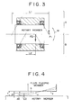
- a force F1 applied to the bearings by a moment load M is represented by the following numerical formula.
- the annular gap of the present invention becomes different from that of the prior art. That is, in the former case, the inner surface of the fluid feeding member is shown by a state of b and a minimum gap is made to E1, whereas, in the latter case, the inner surface of the fluid feeding member is shown by a state c and a minimum gap is made to E2.
- the minimum gap of the annular gap in the case embodoying the present invention is larger at AE than that of the prior art, and thus the annular gap of the present invention can be made smaller to that extent than that of the prior art. Further, this means that the amount of the eccentric displacement of the annular gap with respect to the rotary member is made smaller than the prior art.
- the longitudinal length thereof can be made sufficiently small, and heat eventually generated by rotation is greatly reduced as apparent from the aforementioned numerical formulas.
- the fluid feeding member of a short length suffices, a machine tool can be made compact.
- the annular gap is displaced to its maximum eccentric state, the amount of fluid passing through the annular gap becomes 2.5 times larger than that when the annular gap is in the concentric state. Accordingly, the smaller amount of fluid is leaked when the annular gap is closer to the concentric state.
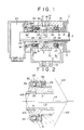
- Figure 1 illustrates a coupling mechanism for a rotary fluid cylinder embodying the present invention, wherein 1 designates a rotary member coaxially coupled to a spindle or the like of a lathe and having a rotary shaft l a.
- a piston member 2 is coaxially provided at the center of the rotary member 1 in such a manner that it is free to slide and displace along the center axis c1 of the rotary member 1.
- Respective independent fluid chambers are defined at the left end in Figure 1 of the rotary member 1, and respective oil paths 5, 6 formed in the rotary shaft 1 communicate with the respective fluid chambers.
- a cylindrical fluid supply member 7 to which operating fluid is supplied from the outside is mounted over the rotary shaft 1 a via a sleeve 8 as an integral part of the fluid supply member 7.
- Designated at 9 and 10 are ring-shaped oil grooves defined on the outer circumference of the sleeve 8, and designated at 11 and 12 are similar ring-shaped oil grooves defined on the inner circumference thereof.
- the oil grooves 9, 10 communicate with the oil grooves 11, 12 through respective oil paths 13, 14 extended in the radial directions.
- Deep-groove ball bearings 27, 28 are interposed between the respective ends of the sleeve 8 and the shaft l a, and the above fluid supply member 7 mounted through these deep-groove ball bearings 15, 16 enables the shaft 1 a to be free to rotate and displace.
- Designated at 17 and 18 are fluid supply/discharge ports, designated at 19 is a leaked oil discharge port, designated at 33 is an oil thrower fixed to the shaft 1 a by bolts, and designated at 23 is a rear cover.
- a stepped portion 1 b is defined on the shaft 1 a of the rotary member 1 to form a small-diameter portion.
- the sleeve 8 has cutouts defined on the insides of the opposite extreme ends thereof, a hole 8a is formed on the bottom of one of the cutouts, deep-groove ball bearings 27, 28 are inserted into the respective cutouts, a spring 29 is loosely inserted into the hole 8a, and a retainer 31 held in abutment against the outer ring 30 of the bearing 28 is interposed between the spring 29 and the bearing 28 in such a manner that the retainer 31 can be displaced in the direction along the shaft 1 a.
- the two bearings 27, 28 are inserted over the above small-diameter portion: one of them, the bearing 27 is locked to the above-stepped portion 1 b; and the other of them, the bearing 28 is mounted in such a manner that the inner ring 35 thereof is held in abutment against a fringer 34 and supported thereby.
- the rear portion of the fringer 34 is supported by the oil thrower 33 fixed to the end of the small-diameter portion by bolts 32, so that the displacement of the bearing 28 in the left direction in Figure 1 is regulated.
- the spring 29 is compressed to a suitable length to apply a predetermined amount of extending force, and the sleeve 8 can make a predetermined amount of slide in the direction of the center axis thereof with respect to the main body 7a and the partition member 7b of the fluid supply member 7.
- the extending force of the spring 29 presses the outer ring 30 of the deep-groove bearing 28 through the retainer 31 in the left direction against the inner ring 35 thereof whose displacement in the left direction is regulated.
- the sleeve 8 is pressed in the right direction along the shaft 1 a, and the outer ring 36 of the other bearing 27 is pressed in the right direction against the inner ring 37 thereof whose displacement in the right direction is regulated by the reaction caused by the above pressing action.
- the relationship between the outer and inner rings, 36, 37, and 30, 35 of the respective deep-groove ball bearings 27, 28 and rolling members 38, 39 is arranged as shown in Figure 2, so that the distance L2 between the cross points of the contact lines m3 and center axis of rotation c4 thereof is increased. More specifically, the deep-groove bearings 27, 28 are biased to move away from each other by a predetermined pre-load applied to the bearings 27, 28 by the spring 29.
- pressurized oil is suitably supplied from a not-shown external operation fluid supply/discharge unit to any of the fluid chambers through the fluid supply/discharge port 17 or 18, the oil grooves 9 and 11, or 10 and 12 of the sleeve, the oil paths 13 or 14 and the oil path 5 or 6, and the like, the piston member 2 is slidingly displaced in a predetermined direction along the center axis of the rotary member 1, whereby the jaws of the chuck, not shown, are suitably opened and closed. Further, pressurized oil continuously fed to the fluid chamber after the jaws have gripped enables the jaws to grip a workpiece by a predetermined force even if the chuck rotates at a high speed.
- Figures 5 and 6 show modified embodiments of the present invention which employs a cup spring 29A as the pre-loading member, wherein the relative arrangement of the deep-groove ball bearings 27, 28, the sleeve 8 and the cup spring 29A is changed thereby to increase the distance L2 between the cross points of contact lines m3 and center axes C of rotation.
- the annular gap defined between the sleeve and the shaft can be made smaller than that of the prior art so that heat generated by rotation can be greatly reduced while keeping the amount of oil leaking to a conventional level.
- the longitudinal length of the annular gap i.e., the axial length of the sleeve can be shortened, whereby a machine tool can be made compact.
- the deep-groove ball bearings are employed as the rolling bearings, the bearings are less expensive and the useful life thereof can be prolonged because they can be used twice by reversing the front and back sides thereof.
Landscapes
- Engineering & Computer Science (AREA)
- Mechanical Engineering (AREA)
- Rolling Contact Bearings (AREA)
- Gripping On Spindles (AREA)
Applications Claiming Priority (1)
| Application Number | Priority Date | Filing Date | Title |
|---|---|---|---|
| US07/595,264 US5065792A (en) | 1990-10-09 | 1990-10-09 | Coupling mechanisms for rotary fluid cylinders |
Publications (1)
| Publication Number | Publication Date |
|---|---|
| EP0480084A1 true EP0480084A1 (de) | 1992-04-15 |
Family
ID=24382508
Family Applications (1)
| Application Number | Title | Priority Date | Filing Date |
|---|---|---|---|
| EP90119337A Withdrawn EP0480084A1 (de) | 1990-10-09 | 1990-10-09 | Kupplungsmechanismus für drehende Flüssigkeitszylinder |
Country Status (2)
| Country | Link |
|---|---|
| US (1) | US5065792A (de) |
| EP (1) | EP0480084A1 (de) |
Families Citing this family (6)
| Publication number | Priority date | Publication date | Assignee | Title |
|---|---|---|---|---|
| DE4124153A1 (de) * | 1991-07-20 | 1993-01-21 | Smw Spanneinrichtungen | Einrichtung zur uebertragung eines mediums |
| DE4244812C2 (de) * | 1992-01-25 | 1998-05-28 | Escher Wyss Gmbh | Heiz- oder Kühlwalze |
| JP3541351B2 (ja) * | 2000-03-13 | 2004-07-07 | 新キャタピラー三菱株式会社 | 作業機械の配管構造 |
| US6401746B1 (en) * | 2000-10-25 | 2002-06-11 | Grant E. Scott, Jr. | Rotating union for fluids, semi-fluids, gaseous fluids and other materials |
| JP2006505408A (ja) * | 2001-11-23 | 2006-02-16 | エス・エム・エス・デマーク・アクチエンゲゼルシャフト | 油膜軸受の流体静力学的な設備の液圧供給導管のための接続ブロック |
| US9383051B1 (en) | 2012-05-17 | 2016-07-05 | The Boeing Company | Shrouded dynamically sealed rotary coupling |
Citations (1)
| Publication number | Priority date | Publication date | Assignee | Title |
|---|---|---|---|---|
| EP0220558A2 (de) * | 1985-10-23 | 1987-05-06 | Günter Horst Röhm | Druckmittelverteiler für umlaufende Spannzylinder |
Family Cites Families (9)
| Publication number | Priority date | Publication date | Assignee | Title |
|---|---|---|---|---|
| US2357381A (en) * | 1943-04-29 | 1944-09-05 | Jack & Heintz Inc | Flight instrument |
| US2831651A (en) * | 1957-04-19 | 1958-04-22 | Pure Oil Co | Switching device for high temperature multi-reactor processes |
| US2913002A (en) * | 1957-08-14 | 1959-11-17 | Janas Bronislaus | Rotating pick-up unit |
| US3381704A (en) * | 1965-04-22 | 1968-05-07 | Howard M. Richardson | Hose reel |
| FR2198594A5 (de) * | 1972-09-06 | 1974-03-29 | Secmer Sa | |
| US4168654A (en) * | 1976-06-14 | 1979-09-25 | Logansport Machine Co., Inc. | Fluid supply distributor |
| IL78582A0 (en) * | 1986-04-22 | 1986-08-31 | Amcor Ltd | Air feed tube assembly for a pneumatic chuck |
| SE455629B (sv) * | 1986-11-25 | 1988-07-25 | Flygt Ab | Rotationskoppling |
| US4848400A (en) * | 1988-02-19 | 1989-07-18 | Fsi International, Inc. | Rotary fluid coupling |
-
1990
- 1990-10-09 US US07/595,264 patent/US5065792A/en not_active Expired - Fee Related
- 1990-10-09 EP EP90119337A patent/EP0480084A1/de not_active Withdrawn
Patent Citations (1)
| Publication number | Priority date | Publication date | Assignee | Title |
|---|---|---|---|---|
| EP0220558A2 (de) * | 1985-10-23 | 1987-05-06 | Günter Horst Röhm | Druckmittelverteiler für umlaufende Spannzylinder |
Also Published As
| Publication number | Publication date |
|---|---|
| US5065792A (en) | 1991-11-19 |
Similar Documents
| Publication | Publication Date | Title |
|---|---|---|
| US4791841A (en) | Chucking device | |
| US3911707A (en) | Finishing tool | |
| US4947668A (en) | Rolling milling tool | |
| EP0315567B2 (de) | Selbstbelastende Durchbiegungsausgleichswalze | |
| EP1015158A1 (de) | Hydraulische druckvorrichtung | |
| EP0480084A1 (de) | Kupplungsmechanismus für drehende Flüssigkeitszylinder | |
| US6050173A (en) | Cam motor apparatus | |
| US3493273A (en) | Hydrostatic machine tool spindle | |
| US2577858A (en) | High-speed rotating cylinder | |
| US3933061A (en) | Apparatus for hydraulically operating the chuck of the hollow spindle of a lathe | |
| GB2176252A (en) | Axial piston machine | |
| US2849244A (en) | O-ring seal for rotary hydraulic cylinder | |
| US3461752A (en) | Precision boring grooving and recessing head | |
| JPS6145072B2 (de) | ||
| JP2875283B2 (ja) | 工作物係合手段の作動機構 | |
| EP0415374A1 (de) | Zuführmechanismus mit einem durch ein hydrostatisches Lager geführten Gleitteil | |
| US3892503A (en) | Apparatus and method for multiple mode motor | |
| US4048701A (en) | Deflection compensating roll | |
| US4762050A (en) | Rotary hydraulic actuator | |
| GB2163679A (en) | Integral spring flexure for use with high speed rotating tool shaft | |
| US4508010A (en) | Hydraulic motor | |
| CN101678472A (zh) | 作业机械 | |
| SE444839B (sv) | Kolvmaskin | |
| US2751230A (en) | Hydraulic chuck | |
| GB2063749A (en) | Rotary clamping cylinder with a clamping piston for clamping devices on machine tools |
Legal Events
| Date | Code | Title | Description |
|---|---|---|---|
| PUAI | Public reference made under article 153(3) epc to a published international application that has entered the european phase |
Free format text: ORIGINAL CODE: 0009012 |
|
| AK | Designated contracting states |
Kind code of ref document: A1 Designated state(s): AT BE CH DE DK ES FR GB GR IT LI LU NL SE |
|
| RBV | Designated contracting states (corrected) |
Designated state(s): CH DE FR GB IT LI NL SE |
|
| STAA | Information on the status of an ep patent application or granted ep patent |
Free format text: STATUS: THE APPLICATION IS DEEMED TO BE WITHDRAWN |
|
| 18D | Application deemed to be withdrawn |
Effective date: 19921016 |