EP0479778B1 - Arrangement for hydraulically or pneumatically operated gripping or holding device - Google Patents
Arrangement for hydraulically or pneumatically operated gripping or holding device Download PDFInfo
- Publication number
- EP0479778B1 EP0479778B1 EP89907326A EP89907326A EP0479778B1 EP 0479778 B1 EP0479778 B1 EP 0479778B1 EP 89907326 A EP89907326 A EP 89907326A EP 89907326 A EP89907326 A EP 89907326A EP 0479778 B1 EP0479778 B1 EP 0479778B1
- Authority
- EP
- European Patent Office
- Prior art keywords
- casing
- section
- gripping
- chamber
- arrangement
- Prior art date
- Legal status (The legal status is an assumption and is not a legal conclusion. Google has not performed a legal analysis and makes no representation as to the accuracy of the status listed.)
- Expired - Lifetime
Links
Images
Classifications
-
- B—PERFORMING OPERATIONS; TRANSPORTING
- B25—HAND TOOLS; PORTABLE POWER-DRIVEN TOOLS; MANIPULATORS
- B25J—MANIPULATORS; CHAMBERS PROVIDED WITH MANIPULATION DEVICES
- B25J15/00—Gripping heads and other end effectors
- B25J15/08—Gripping heads and other end effectors having finger members
- B25J15/12—Gripping heads and other end effectors having finger members with flexible finger members
-
- B—PERFORMING OPERATIONS; TRANSPORTING
- B25—HAND TOOLS; PORTABLE POWER-DRIVEN TOOLS; MANIPULATORS
- B25J—MANIPULATORS; CHAMBERS PROVIDED WITH MANIPULATION DEVICES
- B25J15/00—Gripping heads and other end effectors
- B25J15/0009—Gripping heads and other end effectors comprising multi-articulated fingers, e.g. resembling a human hand
Definitions
- the present invention concerns an arrangement for an hydraulically or pneumatically operated gripping or holding device with attached gripping or holding parts.
- the arrangement is in the form of a so-called "robot hand” with two or more "robot fingers”. Gripping and holding devices are adjustable from a bent gripping or holding mode to an extended release mode in relation to an object to be gripped or held, and vice versa.
- the present invention will find general application as a gripping or holding device and more particularly as a robot hand which can be put to various uses in the field of technology.
- the invention is not limited to such technical applications, but can for instance also be used as a hand prosthesis by persons with a defective or missing hand.
- the object of the present invention is to avoid the above problems by producing a relatively simple and reliable solution.
- the solution may be applied to a wide range of fields. While aiming at avoiding special sensors, the aim is to produce an even and controlled action on the object to be gripped or held.
- a grapling device comprising an arm formed from a closed ended, inflatable tube of elastic material.
- the tube has a plurality of generally parallel, longitudinally spaced bands disposed therearound for limiting the radial distention of the arm when inflated.
- a longitudinally inelastic, laterally flexible band disposed on a surface of the arm causes the arm, when inflated to wrap around an object to be gripped. The extent of the inflation of the arm determines the gripping force and geometry of the device.
- the arangement is characterised in that the first casing section and the partition section is made of soft and flexible material, and that the second casing section is made of rather rigid flexible material, incorporates the stiffening element, has a wall thickness more than 2-3 times thicker than the thickness of the first casing section respectively the partition section and has an axial lenght less than that of the first casing section, whereas the volume of the first casing chamber is substantially larger and by preference 4-5 times larger than the volume of the second casing chamber, and that the casing in its unloaded condition takes a position between maximally curved and maximally extended positions.
- the invention imitates the properties of the human hand as far as skin, muscles, etc., are concerned, so that the arrangement can easily be adapted locally according to the surroundings, according to need.
- a flexible or articulated stiffening element inside the above-mentioned casing it is possible in the same manner to imitate the properties of the human hand when it comes to joints, ligaments, tendons, etc., so that the arrangement can also adjusted with regard to rigidity and strenght.
- the above-mentioned pressure medium is a common working pressure medium for the gripping and holding parts so as to carry out an evenly distributed squeezing force on each of the gripping and holding parts.
- a common pressure medium source for all movements to be carried out by the gripping and holding device, including all possible separate movements which the individual gripping and holding part is to make in connection with its engagement with a common object that is to be gripped or held.
- a simple, common governor pressure governing device to control the pressure in accordance with need or to reverse the connection between the pressure chamber(s) and the pressure medium source or the pressure relief source.
- the arrangement in the invention as an internally stiffened device similar to a rubber glove with a shape similar to or generally similar to a human hand, it is possible to obtain a handy tool which can act more or less like a closed hand when it is supplied with a pressure medium to an attached (first) chamber or as an open hand when the pressure medium is removed from the attached chamber.
- a second chamber in connection with the first chamber and similarly to remove the pressure medium from a second chamber when the first chamber is supplied with pressure medium or supply pressure medium to the second chamber when pressure medium is removed from the first chamber.
- a pressure medium source or a pressure medium reservoir 10 is shown with a pipe connection 11 to a pressure governor 12 and with a further pipe connection 13 from the pressure governor 12 to a four-way valve 14 inlet 15.
- At 12a there is a wheel to adjust the pressure of the medium in pressure governor 12 and at 14a there is a handle to control the supply of the pressure medium to or from outlets 18 and 22 and to control the amount of pressure medium to and from the outlets and the adjacent chambers 20 and 24.
- the robot hand 21 is shown in fig. 1 with a robot hand casing 25 and is also shown with a chamber section 20a which imitates the palm and back of a hand and with five chamber sections imitating fingers 20b,20c,20d,20e,20f which communicate with each other and with the section 20a.
- a second chamber 24 Inside the chamber sections 20a-20f, i.e. inside a first chamber 20, there is a second chamber 24 with a hand chamber section 24a and five finger chamber sections 24b,24c,24d,24e,24f, communicating between themselves and with section 24a.
- valve 14 it is possible to supply the device with a desired amount of pressure medium to the one chamber, for instance chamber 20, while at the same time a corresponding amount or a thereto adjusted amount of pressure medium is removed from the second chamber, i.e. chamber 24, and vice versa.
- the individual sections of the robot hand and robot fingers may be flexed separately to adjust to the shape of the object to be gripped or held, that is to say with an even distribution of the force on the individual sections as these are applied to and stop up against the individual local sections of the object.
- by removing the pressure medium from the one chamber and supplying pressure medium to the other chamber it is possible to adjust the degree to which the robot hand and robot fingers are extended.
- the actual force exerted by the local sections of the robot hand can be controlled collectively by the governor 12.
- the palm of the hand section 20a,24a of the robot hand may also be stiffened, possibly in extension of a stiffening of the various robot fingers. It is also possible to allow certain areas of the palm section 20a,24a to be immovably stiffened, while other areas of the palm section 20a,24a can be stiffened in a flexible fashion, corresponding to the finger sections.
- Figs. 2-4 show a first design example, showing an outer, soft and flexible casing 25'.
- the casing 25' is divided lengthwise into a longitudinal first chamber 20b with a relatively large volume and a longitudinal second chamber 24b with a smaller volume.
- the chamber 20b can, for instance, have a volume which is 4-5 times as large as the volume of chamber 24b.
- the back of the casing of the above-mentioned first chamber 20b is equipped with a soft, bellows-shaped casing section 25a, while on the opposite side, it is equipped with a flexible, soft section 25b forming a partition wall.
- the second chamber 24b is located between the first chamber 20b and the inside of the casing, where a flexible casing section 25c is shown. As shown in fig.
- the casing section 25a, the partition section 25b and the casing section 25c are linked together through a connection area 25d with little width b".
- the casing section 25a and the partition section 25b have a thickness a which is less than 1/2 and preferably less than 1/3 of the thickness a' of the casing section 25c. More precisely, the casing section 25' has a thickness a' which is in the region of 1/10 to 1/20 of the width b' of the casing section 25c.
- the casing 25' as shown in fig. 2 when under pressure has a width b (generally corresponding to width b' of the casing section 25c) which is about 1/4 of the length of the casing l.
- the above-mentioned width may for instance vary between 1/3 and 1/10 of the length of the casing l.
- the relatively rigid but flexible casing section 25c extends along most of the length of the casing l and preferably with a more or less even thickness over the whole length and over the whole width, with the exception of the end edge sections and the side edge sections where the casing section 25c forms an evenly decreasing partition thickness at the transition to the adjacent casing sections.
- a stiffening element is formed in casing 25'. This stiffening element is allowed to bend in the above-mentioned plane P (bending plane) as shown in fig. 4, but is prevented from bending in directions at right angles to the above-mentioned plan P.
- the casing section 25c' as shown in fig. 5, to be equipped with constricted sections 27a,27b,27c, forming swing-joints in certain sections of the casing section's 25c' length.
- the areas 28a,28b,28c,28d of the casing section 25c' adjacent to the constricted sections can be relatively rigid and have only a minimum of flexibility.
- Fig. 2 shows the casing section 25a in a mode where the finger chamber 20b takes up a pressure relief position and where the casing section 25a has a bellows section shown in an axially collapsed mode.
- the finger chamber 24b takes up its fully pressure-loaded mode, where the partition wall 25b and the casing section 25c are maximally extended both lengthwise and widthwise.
- Fig. 3 shows the finger section 21b after pressure has been released from the finger chamber 24b and the partition section 25b has been pressed against the casing section 25c with the help of the pressure-loaded finger chamber 20b.
- the flexible casing section 25c as shown in fig. 3, (or the jointed casing section 25c' as shown in fig. 5) is bent over in a more or less C-shaped fashion, i.e. in a curve determined by the degree to which finger chamber 20b is filled and the degree to which finger chamber 24b is emptied.
- Fig. 4 shows a cross-section of the casing 25 with a mean loading of both finger chamber 20b and finger chamber 24b.
- the alternative design is dimensioned and constructed in a manner corresponding to that shown in fig. 2 to 4 and 5, but where the casing 125 is shown with a single finger chamber 120b, as the partition corresponding to partition 25b shown in figs. 2-4 has been omitted.
- the casing section 125a is shown with sectionally arranged, transverse ribs 30 and intermediate membrane-forming sections 31.
- the casing section 125c is specially stiffened with a leaf spring 32 built into the casing section 125c, such spring extending over most of the length and width of the casing section 125c, as shown in fig. 8.
Landscapes
- Engineering & Computer Science (AREA)
- Robotics (AREA)
- Mechanical Engineering (AREA)
- Manipulator (AREA)
- Forklifts And Lifting Vehicles (AREA)
- Load-Engaging Elements For Cranes (AREA)
- Prostheses (AREA)
- Clamps And Clips (AREA)
Abstract
Description
- The present invention concerns an arrangement for an hydraulically or pneumatically operated gripping or holding device with attached gripping or holding parts. As an example, the arrangement is in the form of a so-called "robot hand" with two or more "robot fingers". Gripping and holding devices are adjustable from a bent gripping or holding mode to an extended release mode in relation to an object to be gripped or held, and vice versa.
- The present invention will find general application as a gripping or holding device and more particularly as a robot hand which can be put to various uses in the field of technology. However, the invention is not limited to such technical applications, but can for instance also be used as a hand prosthesis by persons with a defective or missing hand.
- Up to now, such a gripping or holding device has been based on electro-mechanical operation to produce the desired gripping and holding operations. Such known devices (pincers or the like) have been complicated and costly both as regards production and operation, and have therefore not received as wide an application as one might wish. It must also be said that such devices are particular sensitive to outside influences and therefore less suited to relatively "dirty" environments and in environments where the device may be affected by active fluids, etc. A further problem is that such devices depend on sensors for feedback from the gripping surface(s) to the governing system, particularly in cases where it is necessary to handle the object to be gripped or held carefully or gently.
- The object of the present invention is to avoid the above problems by producing a relatively simple and reliable solution. As construction and mode of operation are simple, the solution may be applied to a wide range of fields. While aiming at avoiding special sensors, the aim is to produce an even and controlled action on the object to be gripped or held.
- In US 4 815 782 is suggested a grapling device comprising an arm formed from a closed ended, inflatable tube of elastic material. The tube has a plurality of generally parallel, longitudinally spaced bands disposed therearound for limiting the radial distention of the arm when inflated. A longitudinally inelastic, laterally flexible band disposed on a surface of the arm causes the arm, when inflated to wrap around an object to be gripped. The extent of the inflation of the arm determines the gripping force and geometry of the device.
- By using elastic tube material in combination with inelastic, laterally flexible band a main part of the inflating force is being used to expand or deform the elastic tube material and to bend the inelastic, laterally flexible band into a curved shape, whereas the gripping force of the grappling device, when being wrapped around an object to be gripped is reduced correspondingly. It is also a problem to provide an accurate gripping force without the use of special sensors.
- According to the invention the arangement is characterised in that the first casing section and the partition section is made of soft and flexible material, and that the second casing section is made of rather rigid flexible material, incorporates the stiffening element, has a wall thickness more than 2-3 times thicker than the thickness of the first casing section respectively the partition section and has an axial lenght less than that of the first casing section, whereas the volume of the first casing chamber is substantially larger and by preference 4-5 times larger than the volume of the second casing chamber, and that the casing in its unloaded condition takes a position between maximally curved and maximally extended positions.
- The characteristic features of the present invention and in particular that the axial lenght of the second casing is less than that of the first casing, gives the advantage over prior art that less effort is needed to adjust the gripper to the curved position. This means that a greater part of the force is left to grip the object and in addition that the gripping force is allowed to be set more accurately in practice.
- In as much as a pressure medium containing a working chamber in connection with a relatively soft and flexible casing material has been chosen in connection with the invention, the invention imitates the properties of the human hand as far as skin, muscles, etc., are concerned, so that the arrangement can easily be adapted locally according to the surroundings, according to need. By using a flexible or articulated stiffening element inside the above-mentioned casing, it is possible in the same manner to imitate the properties of the human hand when it comes to joints, ligaments, tendons, etc., so that the arrangement can also adjusted with regard to rigidity and strenght.
- With the help of the arrangement in the invention, it is possible to achieve a solution as regards construction and user properties which to a substantial degree can imitate the construction and workings of the human hand. In most instances where the human hand is to carry out a gripping, holding or lifting operation, it is not a question of moving each finger separately and one at a time, joint by joint, but rather of moving the fingers together in a common grip with the gripping force adjusted to the shape of the object to be gripped or held, with a more or less even squeezing force between each finger and the object to be gripped or held. All fingers will thus move at the same time towards a closed (flexed) mode or at the same time away from a closed mode towards a more extended mode. A similar effect is achieved in a simple manner with the help of the robot hand of this invention. In the closing movement for the robot hand, the bending of the robot fingers will cease as soon as the pressure of the part against the object has reached a certain level, governed by a corresponding movement of the parts of other robot fingers or other parts of the robot hand.
- According to the invention, it is preferable for the above-mentioned pressure medium to be a common working pressure medium for the gripping and holding parts so as to carry out an evenly distributed squeezing force on each of the gripping and holding parts. In this way, it is possible in a simple manner to achieve an effect which by and large corresponds to the workings of a human hand when it is bent around an object that is to be gripped or held.
- According to the invention, it is possible to use a common pressure medium source for all movements to be carried out by the gripping and holding device, including all possible separate movements which the individual gripping and holding part is to make in connection with its engagement with a common object that is to be gripped or held. Moreover, it is possible to use a simple, common governor (pressure governing device) to control the pressure in accordance with need or to reverse the connection between the pressure chamber(s) and the pressure medium source or the pressure relief source.
- By designing the arrangement in the invention as an internally stiffened device similar to a rubber glove with a shape similar to or generally similar to a human hand, it is possible to obtain a handy tool which can act more or less like a closed hand when it is supplied with a pressure medium to an attached (first) chamber or as an open hand when the pressure medium is removed from the attached chamber. To assist the closing and opening movements of the device, it is possible to use a second chamber in connection with the first chamber and similarly to remove the pressure medium from a second chamber when the first chamber is supplied with pressure medium or supply pressure medium to the second chamber when pressure medium is removed from the first chamber.
- Further characteristics of the invention will appear from the following description, which refers to the appended drawings, in which:
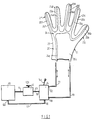
- Fig. 1 shows a diagram of an arrangement in accordance with the invention, illustrated in connection a gripping and holding device imitating a human hand (robot hand).
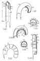
- Fig. 2 shows a side view and a partial cross section of a first design example of a gripping and holding part (robot finger part) forming part of the device as shown in fig. 1, in extended mode.
- Fig. 3 shows the same as fig. 2 with the part shown in flexed mode.
- Fig. 4 shows a cross-section of the part according to fig. 2.
- Fig. 5 shows a drawing of a modification of a detail of the holding part corresponding to fig. 3.
- Figs. 6, 7 and 8 show a second design example in outlines and sections corresponding to figs. 2, 3 and 4.
- In the following, the arrangement will be described using hydraulic oil as a pressure medium, but it will be understood that with correspondingly adapted components, compressed air can be used as a pressure medium, and then generally with the same advantages.
- In fig. 1 a pressure medium source or a
pressure medium reservoir 10 is shown with apipe connection 11 to apressure governor 12 and with afurther pipe connection 13 from thepressure governor 12 to a four-way valve 14inlet 15. From thevalve 14, there is apipe connection 17 from therelief outlet 16 back to thereservoir 10 through a pressure relief source as indicated at 10a. Furthermore, from a first valve outlet 18, there is apipe connection 19 to afirst working chamber 20 in a gripping and holding device which is shown in the form of arobot hand 21 with fiverobot fingers 21b-21f. From asecond valve outlet 22 there is apipe connection 23 to asecond working chamber 24 in therobot hand 21. At 12a, there is a wheel to adjust the pressure of the medium inpressure governor 12 and at 14a there is a handle to control the supply of the pressure medium to or fromoutlets 18 and 22 and to control the amount of pressure medium to and from the outlets and theadjacent chambers - The
robot hand 21 is shown in fig. 1 with arobot hand casing 25 and is also shown with a chamber section 20a which imitates the palm and back of a hand and with five chambersections imitating fingers first chamber 20, there is asecond chamber 24 with a hand chamber section 24a and fivefinger chamber sections - With the help of
valve 14, it is possible to supply the device with a desired amount of pressure medium to the one chamber, forinstance chamber 20, while at the same time a corresponding amount or a thereto adjusted amount of pressure medium is removed from the second chamber,i.e. chamber 24, and vice versa. One can hereby adjust the flexion or extension of therobot hand 21 according to need. The individual sections of the robot hand and robot fingers may be flexed separately to adjust to the shape of the object to be gripped or held, that is to say with an even distribution of the force on the individual sections as these are applied to and stop up against the individual local sections of the object. Similarly, by removing the pressure medium from the one chamber and supplying pressure medium to the other chamber it is possible to adjust the degree to which the robot hand and robot fingers are extended. The actual force exerted by the local sections of the robot hand can be controlled collectively by the governor 12. - In order to achieve the desired flexion or extension of the robot hand, it is necessary to have a special, controlled stiffening of the local areas of the robot hand.
- In the following, such a stiffening is described in connection with a robot finger, but without showing this in detail, it is clear that the palm of the hand section 20a,24a of the robot hand may also be stiffened, possibly in extension of a stiffening of the various robot fingers. It is also possible to allow certain areas of the palm section 20a,24a to be immovably stiffened, while other areas of the palm section 20a,24a can be stiffened in a flexible fashion, corresponding to the finger sections.
- Figs. 2-4 show a first design example, showing an outer, soft and flexible casing 25'. The casing 25' is divided lengthwise into a longitudinal
first chamber 20b with a relatively large volume and a longitudinalsecond chamber 24b with a smaller volume. Thechamber 20b can, for instance, have a volume which is 4-5 times as large as the volume ofchamber 24b. The back of the casing of the above-mentionedfirst chamber 20b is equipped with a soft, bellows-shaped casing section 25a, while on the opposite side, it is equipped with a flexible,soft section 25b forming a partition wall. Thesecond chamber 24b is located between thefirst chamber 20b and the inside of the casing, where aflexible casing section 25c is shown. As shown in fig. 4, the casing section 25a, thepartition section 25b and thecasing section 25c are linked together through aconnection area 25d with little width b". The casing section 25a and thepartition section 25b have a thickness a which is less than 1/2 and preferably less than 1/3 of the thickness a' of thecasing section 25c. More precisely, the casing section 25' has a thickness a' which is in the region of 1/10 to 1/20 of the width b' of thecasing section 25c. In the design example shown, the casing 25' as shown in fig. 2 when under pressure, has a width b (generally corresponding to width b' of thecasing section 25c) which is about 1/4 of the length of the casing l. In various design examples, the above-mentioned width may for instance vary between 1/3 and 1/10 of the length of the casing l. The relatively rigid butflexible casing section 25c extends along most of the length of the casing l and preferably with a more or less even thickness over the whole length and over the whole width, with the exception of the end edge sections and the side edge sections where thecasing section 25c forms an evenly decreasing partition thickness at the transition to the adjacent casing sections. With the help of the transverse, relatively rigidflexible casing section 25c, but which has a bending plane P (fig. 4), a stiffening element is formed in casing 25'. This stiffening element is allowed to bend in the above-mentioned plane P (bending plane) as shown in fig. 4, but is prevented from bending in directions at right angles to the above-mentioned plan P. - It is also possible, in a modified design, for the
casing section 25c', as shown in fig. 5, to be equipped with constrictedsections areas casing section 25c' adjacent to the constricted sections can be relatively rigid and have only a minimum of flexibility. - Fig. 2 shows the casing section 25a in a mode where the
finger chamber 20b takes up a pressure relief position and where the casing section 25a has a bellows section shown in an axially collapsed mode. In this mode, thefinger chamber 24b takes up its fully pressure-loaded mode, where thepartition wall 25b and thecasing section 25c are maximally extended both lengthwise and widthwise. - Fig. 3 shows the
finger section 21b after pressure has been released from thefinger chamber 24b and thepartition section 25b has been pressed against thecasing section 25c with the help of the pressure-loadedfinger chamber 20b. In this mode theflexible casing section 25c as shown in fig. 3, (or the jointedcasing section 25c' as shown in fig. 5) is bent over in a more or less C-shaped fashion, i.e. in a curve determined by the degree to whichfinger chamber 20b is filled and the degree to whichfinger chamber 24b is emptied. - Fig. 4 shows a cross-section of the
casing 25 with a mean loading of bothfinger chamber 20b andfinger chamber 24b. - The alternative design is dimensioned and constructed in a manner corresponding to that shown in fig. 2 to 4 and 5, but where the
casing 125 is shown with asingle finger chamber 120b, as the partition corresponding to partition 25b shown in figs. 2-4 has been omitted. In this design, thecasing section 125a is shown with sectionally arranged,transverse ribs 30 and intermediate membrane-formingsections 31. In this instance, as shown in figs. 6 and 7, one obtains a bellows-like effect corresponding to that shown in figs. 2 and 3, but different in that a radial expansion is obtained only insections 31 while theribs 30 take on a stable form. With the help of an interactive effect between the flexible but otherwiserigid casing section 125c and theribs 30, one obtains a similar joint-forming effect as shown at theconstricted sections casing section 25c' in fig. 5. In the design example shown in figs. ,6-8, thecasing section 125c is specially stiffened with a leaf spring 32 built into thecasing section 125c, such spring extending over most of the length and width of thecasing section 125c, as shown in fig. 8. - In the above-mentioned second design example, one achieves a flexion (fig. 7) or extension (fig. 6) of the
casing 125 solely by loading pressure into or releasing pressure fromfinger chamber 120b. This is ensured by the fact that the leaf spring 32 allows the illustrated bending or flexing ofcasing section 125c by loading pressure into thefinger chamber 120b, while releasing pressure from thefinger chamber 120b ensures the return of the casing section to the position shown in fig. 6. - Instead of attaching the leaf spring 32 as shown, i.e. imbedded into
casing section 125c, it is possible, for instance, to attach the leaf spring tocasing section 125c only at the ends and otherwise allowing the leaf spring to move freely inside thefinger chamber 120b. In such instance, it is possible to design thecasing section 125c between the points at which the leaf spring is attached using a softer wall material or a wall material which will take on a bellows-like form, with less wall thickness, so that this may be folded or creased where the backing so requires. - Even though concrete design examples for this are not shown herein, it is self-evident that the above solutions may be combined in different ways to obtain the desired local rigidity and strength or the desired local flexibility and softness. Thus one here has the possibility of imitating the workings and the appearance of a human hand both with a view to general technical applicability and with a view to its use as a hand prosthesis.
Claims (6)
- The arrangement of an hydraulically or pneumatically operated gripping and holding device with attached gripping and holding parts, i.e. a so-called "robot hand" (21) with two or more "robot fingers" (21a,21c,21d,21e,21f), which is adjustable from a curved gripping and holding position to an extended release position in relation to an object which is to be gripped and/or held, and vice versa, each gripping or holding part comprising a casing (25,125) comprising a first casing section (25a,125a) and a second casing section (25c,125c) and an intermediate partition section (25b,125b) and a stiffening element (24,25c, 125c,32) incorporated in said casing, said casing (25,125) being devided in a first casing chamber (20,20b,120b) between said first casing section and said partition section and a second casing chamber (24,24b,124b) between said second casing section and said partition section, whereas each casing chamber via a regulator (12) separately communicate with a pressure medium charging source and a pressure medium release source, for alternate loading of pressurised medium in one of said chambers and unloading of pressurised medium from the other one of said chambers, and vice versa, characterised in that the first casing section (25a,125a) and the partition section (25b,125b) is made of soft and flexible material, and that the second casing section (25c,125c) is made of rather rigid flexible material, incorporates the stiffening element (24,25c,125c,32), has a wall thickness (a') more than 2-3 times thicker than the thickness (a) of the first casing section (25a,125a) respectively the partition section (25b, 125b) and has an axial lenght less than that of the first casing section (25a,125a), whereas the volume of the first casing chamber (20,20b, 120b) is substantially larger and by preference 4-5 times larger than the volume of the second casing chamber (24,24b, 124b), and that the casing (25,125) in its unloaded condition takes a position between maximally curved and maximally extended positions.
- The arrangement in accordance with claim 1, characterised in that the second casing chamber (24b,124b) is located between the first casing chamber (20b,120b) and the stiffening element (25c,125c,32).
- The arrangement in accordance with claim 1 or 2, characterised in that the main portion of the casing located at the rear side of the casing has a substantially greater lenght than the gripping and holding face thereof, which face is located opposite said rear side of the casing.
- The arrangement in accordance with one of claims 1 to 3, characterised in that the stiffening element forms a partition wall between the first and second casing chambers.
- The arrangement in accordance with one of claims 1 to 4, characterised in that the back of the portion (25a,125a) of the casing is bellow-shaped.
- The arrangement in accordance with one of claims 1 to 4, characterised in that the stiffening element (25c') is joint-shaped.
Priority Applications (2)
| Application Number | Priority Date | Filing Date | Title |
|---|---|---|---|
| DE89907326T DE68909249T2 (en) | 1989-06-21 | 1989-06-21 | ARRANGEMENT FOR A HYDRAULICALLY OR PNEUMATICALLY OPERATED GRIP OR HOLDING DEVICE. |
| AT89907326T ATE94453T1 (en) | 1989-06-21 | 1989-06-21 | ARRANGEMENT FOR A HYDRAULICALLY OR PNEUMATICALLY OPERATED GRIP OR HOLDING DEVICE. |
Applications Claiming Priority (1)
| Application Number | Priority Date | Filing Date | Title |
|---|---|---|---|
| PCT/NO1989/000063 WO1990015696A1 (en) | 1989-06-21 | 1989-06-21 | Arrangement for hydraulically or pneumatically operated gripping or holding device |
Publications (2)
| Publication Number | Publication Date |
|---|---|
| EP0479778A1 EP0479778A1 (en) | 1992-04-15 |
| EP0479778B1 true EP0479778B1 (en) | 1993-09-15 |
Family
ID=19907572
Family Applications (1)
| Application Number | Title | Priority Date | Filing Date |
|---|---|---|---|
| EP89907326A Expired - Lifetime EP0479778B1 (en) | 1989-06-21 | 1989-06-21 | Arrangement for hydraulically or pneumatically operated gripping or holding device |
Country Status (8)
| Country | Link |
|---|---|
| EP (1) | EP0479778B1 (en) |
| JP (1) | JPH05508351A (en) |
| AT (1) | ATE94453T1 (en) |
| DE (1) | DE68909249T2 (en) |
| DK (1) | DK172706B1 (en) |
| FI (1) | FI90512C (en) |
| NO (1) | NO166023C (en) |
| WO (1) | WO1990015696A1 (en) |
Families Citing this family (9)
| Publication number | Priority date | Publication date | Assignee | Title |
|---|---|---|---|---|
| DE69022969T2 (en) | 1989-12-20 | 1996-04-18 | Toshiba Kawasaki Kk | Flexible finger element. |
| JP6721515B2 (en) * | 2014-04-11 | 2020-07-15 | プレジデント アンド フェローズ オブ ハーバード カレッジ | Portable prosthetic hand with soft pneumatic fingers |
| EP3152446B1 (en) * | 2014-06-09 | 2021-04-07 | Soft Robotics, Inc. | Soft robotic actuators utilizing asymmetric surfaces |
| JP6483251B2 (en) * | 2014-09-17 | 2019-03-13 | ソフト ロボティクス, インコーポレイテッド | Soft robot actuator mounting hub assembly |
| JPWO2018230729A1 (en) * | 2017-06-15 | 2020-04-16 | ニッタ株式会社 | Finger structure, gripping device, robot hand, and industrial robot |
| CN109048896A (en) * | 2018-08-10 | 2018-12-21 | 江苏大学 | A kind of atmospheric control for soft robot |
| CN110340921A (en) * | 2019-08-13 | 2019-10-18 | 安徽大学 | A kind of pneumatic type software manipulator with tactilely-perceptible function |
| CN111300459B (en) * | 2020-03-13 | 2022-10-25 | 哈尔滨工业大学 | Multi-degree-of-freedom humanoid rigid-flexible hybrid hand and manufacturing process thereof |
| CN112154991A (en) * | 2020-11-03 | 2021-01-01 | 东北林业大学 | Bionic fly catching grass based on fluid driving |
Family Cites Families (8)
| Publication number | Priority date | Publication date | Assignee | Title |
|---|---|---|---|---|
| US3343864A (en) * | 1965-10-07 | 1967-09-26 | James I Baer | Material handling apparatus and the like |
| US3601442A (en) * | 1970-01-26 | 1971-08-24 | Goodrich Co B F | Gripping device |
| US3640564A (en) * | 1971-01-13 | 1972-02-08 | Goodrich Co B F | Fluid-operated actuator |
| JPS5619001B2 (en) * | 1972-08-04 | 1981-05-02 | ||
| NL177003C (en) * | 1974-05-30 | 1985-07-16 | Freudenberg Carl Fa | MEDIUM PRESSURE AUTOMATIC FINGER. |
| JPS57144687A (en) * | 1981-02-27 | 1982-09-07 | Michio Yoshikawa | Soft gripper having sense function |
| US4815782A (en) * | 1986-12-08 | 1989-03-28 | United Technologies Corporation | Grappling device |
| US4792173A (en) * | 1987-10-30 | 1988-12-20 | Duke University | Fluid actuated limb |
-
1987
- 1987-12-21 NO NO875338A patent/NO166023C/en not_active IP Right Cessation
-
1989
- 1989-06-21 JP JP1507063A patent/JPH05508351A/en active Pending
- 1989-06-21 AT AT89907326T patent/ATE94453T1/en not_active IP Right Cessation
- 1989-06-21 DE DE89907326T patent/DE68909249T2/en not_active Expired - Fee Related
- 1989-06-21 WO PCT/NO1989/000063 patent/WO1990015696A1/en active IP Right Grant
- 1989-06-21 EP EP89907326A patent/EP0479778B1/en not_active Expired - Lifetime
-
1991
- 1991-12-11 DK DK199101994A patent/DK172706B1/en not_active IP Right Cessation
- 1991-12-18 FI FI915951A patent/FI90512C/en active
Also Published As
| Publication number | Publication date |
|---|---|
| WO1990015696A1 (en) | 1990-12-27 |
| DK172706B1 (en) | 1999-06-07 |
| NO166023B (en) | 1991-02-11 |
| NO166023C (en) | 1991-05-22 |
| FI90512B (en) | 1993-11-15 |
| JPH05508351A (en) | 1993-11-25 |
| NO875338D0 (en) | 1987-12-21 |
| EP0479778A1 (en) | 1992-04-15 |
| DK199491A (en) | 1991-12-11 |
| FI90512C (en) | 1994-02-25 |
| FI915951A0 (en) | 1991-12-18 |
| DE68909249D1 (en) | 1993-10-21 |
| ATE94453T1 (en) | 1993-10-15 |
| DE68909249T2 (en) | 1994-01-27 |
| DK199491D0 (en) | 1991-12-11 |
| NO875338L (en) | 1989-07-17 |
Similar Documents
| Publication | Publication Date | Title |
|---|---|---|
| US5568957A (en) | Pressure actuated gripping apparatus and method | |
| US8425438B2 (en) | Motion assist apparatus | |
| US4671258A (en) | Therapeutic multiple joint exerciser | |
| US10548745B2 (en) | Portable prosthetic hand with soft pneumatic fingers | |
| US20210275383A1 (en) | Wearable exoskeleton system and method | |
| CN109009867B (en) | Pneumatic joint structure and joint training ware | |
| EP0479778B1 (en) | Arrangement for hydraulically or pneumatically operated gripping or holding device | |
| Daerden et al. | Pneumatic artificial muscles: actuators for robotics and automation | |
| US4375217A (en) | Compression device with pressure determination | |
| US5593369A (en) | Inflatable hand orthosis | |
| DK2687191T3 (en) | Motion-assist device in the glove form | |
| JP4564788B2 (en) | Wearable power assist device | |
| WO2018136004A1 (en) | A fluid-driven actuator and its applications | |
| GB2255019A (en) | Pressure sleeve for reduction of digital swelling | |
| US3020908A (en) | Mechanical hand | |
| CN110269779B (en) | Hand rehabilitation device based on flexible driver | |
| CN112060114B (en) | Modular multifunctional soft dexterous hand capable of being bent in two directions | |
| US3090049A (en) | Artificial hand | |
| JP6682625B2 (en) | Joint motion assist system | |
| CN113842295A (en) | Bionic bending driver and rehabilitation gloves | |
| CN211067800U (en) | Hand rehabilitation device based on flexible driver | |
| WO1991006404A1 (en) | Controlled flexure element | |
| CN219290037U (en) | Pneumatic glove for assisting joint movement | |
| CN113843769A (en) | Wearable pneumatic flexible outer limb robot | |
| JPS59209785A (en) | Robot hand |
Legal Events
| Date | Code | Title | Description |
|---|---|---|---|
| PUAI | Public reference made under article 153(3) epc to a published international application that has entered the european phase |
Free format text: ORIGINAL CODE: 0009012 |
|
| 17P | Request for examination filed |
Effective date: 19911212 |
|
| AK | Designated contracting states |
Kind code of ref document: A1 Designated state(s): AT BE CH DE FR GB IT LI LU NL SE |
|
| RAP1 | Party data changed (applicant data changed or rights of an application transferred) |
Owner name: HAUGS, AUDUN |
|
| RIN1 | Information on inventor provided before grant (corrected) |
Inventor name: HAUGS, AUDUN |
|
| 17Q | First examination report despatched |
Effective date: 19921016 |
|
| GRAA | (expected) grant |
Free format text: ORIGINAL CODE: 0009210 |
|
| AK | Designated contracting states |
Kind code of ref document: B1 Designated state(s): AT BE CH DE FR GB IT LI LU NL SE |
|
| REF | Corresponds to: |
Ref document number: 94453 Country of ref document: AT Date of ref document: 19931015 Kind code of ref document: T |
|
| ITF | It: translation for a ep patent filed |
Owner name: BUGNION S.P.A. |
|
| REF | Corresponds to: |
Ref document number: 68909249 Country of ref document: DE Date of ref document: 19931021 |
|
| ET | Fr: translation filed | ||
| PLBE | No opposition filed within time limit |
Free format text: ORIGINAL CODE: 0009261 |
|
| STAA | Information on the status of an ep patent application or granted ep patent |
Free format text: STATUS: NO OPPOSITION FILED WITHIN TIME LIMIT |
|
| 26N | No opposition filed | ||
| EAL | Se: european patent in force in sweden |
Ref document number: 89907326.6 |
|
| PGFP | Annual fee paid to national office [announced via postgrant information from national office to epo] |
Ref country code: NL Payment date: 19990603 Year of fee payment: 11 |
|
| PGFP | Annual fee paid to national office [announced via postgrant information from national office to epo] |
Ref country code: CH Payment date: 19990608 Year of fee payment: 11 |
|
| PGFP | Annual fee paid to national office [announced via postgrant information from national office to epo] |
Ref country code: FR Payment date: 19990611 Year of fee payment: 11 |
|
| PGFP | Annual fee paid to national office [announced via postgrant information from national office to epo] |
Ref country code: SE Payment date: 19990616 Year of fee payment: 11 Ref country code: GB Payment date: 19990616 Year of fee payment: 11 |
|
| PGFP | Annual fee paid to national office [announced via postgrant information from national office to epo] |
Ref country code: AT Payment date: 19990621 Year of fee payment: 11 |
|
| PGFP | Annual fee paid to national office [announced via postgrant information from national office to epo] |
Ref country code: DE Payment date: 19990827 Year of fee payment: 11 |
|
| PGFP | Annual fee paid to national office [announced via postgrant information from national office to epo] |
Ref country code: LU Payment date: 20000609 Year of fee payment: 12 |
|
| PG25 | Lapsed in a contracting state [announced via postgrant information from national office to epo] |
Ref country code: GB Free format text: LAPSE BECAUSE OF NON-PAYMENT OF DUE FEES Effective date: 20000621 Ref country code: AT Free format text: LAPSE BECAUSE OF NON-PAYMENT OF DUE FEES Effective date: 20000621 |
|
| PG25 | Lapsed in a contracting state [announced via postgrant information from national office to epo] |
Ref country code: SE Free format text: LAPSE BECAUSE OF NON-PAYMENT OF DUE FEES Effective date: 20000622 |
|
| PGFP | Annual fee paid to national office [announced via postgrant information from national office to epo] |
Ref country code: BE Payment date: 20000627 Year of fee payment: 12 |
|
| PG25 | Lapsed in a contracting state [announced via postgrant information from national office to epo] |
Ref country code: LI Free format text: LAPSE BECAUSE OF NON-PAYMENT OF DUE FEES Effective date: 20000630 Ref country code: CH Free format text: LAPSE BECAUSE OF NON-PAYMENT OF DUE FEES Effective date: 20000630 |
|
| PG25 | Lapsed in a contracting state [announced via postgrant information from national office to epo] |
Ref country code: NL Free format text: LAPSE BECAUSE OF NON-PAYMENT OF DUE FEES Effective date: 20010101 |
|
| GBPC | Gb: european patent ceased through non-payment of renewal fee |
Effective date: 20000621 |
|
| REG | Reference to a national code |
Ref country code: CH Ref legal event code: PL |
|
| EUG | Se: european patent has lapsed |
Ref document number: 89907326.6 |
|
| PG25 | Lapsed in a contracting state [announced via postgrant information from national office to epo] |
Ref country code: FR Free format text: LAPSE BECAUSE OF NON-PAYMENT OF DUE FEES Effective date: 20010228 |
|
| NLV4 | Nl: lapsed or anulled due to non-payment of the annual fee |
Effective date: 20010101 |
|
| REG | Reference to a national code |
Ref country code: FR Ref legal event code: ST |
|
| PG25 | Lapsed in a contracting state [announced via postgrant information from national office to epo] |
Ref country code: DE Free format text: LAPSE BECAUSE OF NON-PAYMENT OF DUE FEES Effective date: 20010403 |
|
| PG25 | Lapsed in a contracting state [announced via postgrant information from national office to epo] |
Ref country code: LU Free format text: LAPSE BECAUSE OF NON-PAYMENT OF DUE FEES Effective date: 20010621 |
|
| PG25 | Lapsed in a contracting state [announced via postgrant information from national office to epo] |
Ref country code: BE Free format text: LAPSE BECAUSE OF NON-PAYMENT OF DUE FEES Effective date: 20010630 |
|
| BERE | Be: lapsed |
Owner name: HAUGS AUDUN Effective date: 20010630 |
|
| PG25 | Lapsed in a contracting state [announced via postgrant information from national office to epo] |
Ref country code: IT Free format text: LAPSE BECAUSE OF NON-PAYMENT OF DUE FEES;WARNING: LAPSES OF ITALIAN PATENTS WITH EFFECTIVE DATE BEFORE 2007 MAY HAVE OCCURRED AT ANY TIME BEFORE 2007. THE CORRECT EFFECTIVE DATE MAY BE DIFFERENT FROM THE ONE RECORDED. Effective date: 20050621 |