EP0479744B1 - A method for reducing the risk of poor reception in a mobile telephony system - Google Patents
A method for reducing the risk of poor reception in a mobile telephony system Download PDFInfo
- Publication number
- EP0479744B1 EP0479744B1 EP91850215A EP91850215A EP0479744B1 EP 0479744 B1 EP0479744 B1 EP 0479744B1 EP 91850215 A EP91850215 A EP 91850215A EP 91850215 A EP91850215 A EP 91850215A EP 0479744 B1 EP0479744 B1 EP 0479744B1
- Authority
- EP
- European Patent Office
- Prior art keywords
- information
- frame
- transmitted
- changed
- polarization direction
- Prior art date
- Legal status (The legal status is an assumption and is not a legal conclusion. Google has not performed a legal analysis and makes no representation as to the accuracy of the status listed.)
- Expired - Lifetime
Links
Images
Classifications
-
- H—ELECTRICITY
- H04—ELECTRIC COMMUNICATION TECHNIQUE
- H04B—TRANSMISSION
- H04B14/00—Transmission systems not characterised by the medium used for transmission
- H04B14/002—Transmission systems not characterised by the medium used for transmission characterised by the use of a carrier modulation
- H04B14/008—Polarisation modulation
-
- H—ELECTRICITY
- H04—ELECTRIC COMMUNICATION TECHNIQUE
- H04B—TRANSMISSION
- H04B7/00—Radio transmission systems, i.e. using radiation field
- H04B7/02—Diversity systems; Multi-antenna system, i.e. transmission or reception using multiple antennas
- H04B7/10—Polarisation diversity; Directional diversity
Definitions
- the present invention relates to a method for reducing in a digital time-multiplex mobile telephony system the risk of poor reception when transmitting from a fixed station to a mobile station, as a result of reflection of transmitted signals by different objects, wherein each information frame to be transmitted is divided into a plurality of information parts determined by the number of interleaving levels.
- a station for example a base station in a mobile telephony system, is equipped with two receiver antennas which are spaced appropriately apart.
- a so-called diversity effect is obtained in the fixed station with the aid of a suitable addition function of two received signals. This is based on the assumption that the probability of both antennas being located simultaneously in a zero point is small.
- each subscriber is divided into information sections, called information frames. These frames are normally called speech frames in speech transmission.
- information frames are normally called speech frames in speech transmission.
- the information in each such frame is divided into a specific number of signal sequences (bursts), which together with corresponding signal sequences from other subscribers form time slots in a plurality of mutually sequential TDMA-frames.
- each TDMA-frame includes information parts, i.e. signal sequences, from several subscribers.
- the number of signal sequences into which the information contained in each information frame is divided is determined by the number of so-called interleaving levels, the so-called interleaving depth in the channel code. In the GSM-system, the interleaving depth is equal to eight, i.e. the content of each information frame is divided into eight signal sequences.
- GB-A-222/820 discloses a polarization diversity radio communication system.
- the object of the present invention is to provide a method of the kind defined in the introduction which will avoid the problems caused by poor reception that results from the occurrence of so-called zero points, both in stations equipped with only one antenna and also in systems having relatively small cell radii and therewith relatively small time dispersion.
- This object is achieved by transmitting from the fixed station with a polarization direction which is changed stepwise between different parts of the information transmitted.
- the fading pattern around the receiver antenna of the mobile station will be changed in time and any occurrent zero points will move in the geography, even in systems having small time dispersion, for example in city environments.
- the polarization direction is changed for each new TDMA-frame in a GSM-system. It is therefore improbable that more than one signal sequence will be lost for a given subscriber.
- the illustrated arrangement uses two antennas both for receiving and transmitting.
- the antennas are referenced 18 and 19 and, when receiving, signals received by the receivers are conducted to a receiving device 11, via two duplex filters 16 and 17.
- signals are generated in a transmission device 10, and are applied to two branches.
- the signals in the two branches are each conducted to a respective antenna 18, 19 via a respective amplitude modulator 12, 13, a respective power amplifier 14, 15, and a respective duplex filter 16, 17.
- the antennas are oriented so as to have different polarization directions therebetween.
- the polarization directions may differ by 90 degrees in relation to one another.
- the amplitude modulators are controlled by signals from a control means 20 and modulate the signals to power amplifiers so that the powers delivered to the two antennas are changed in relation to each other. This results in a change in the polarization direction of the resultant output signal.
- the amplitude should not be changed during an ongoing signal sequence. This is because such systems do not include an equalizer which can adapt to such changes.
- the polarization angle of the resultant signal is therefore changed after each TDMA-frame, by changing the amplitudes of the signals to the two antennas stepwise after each TDMA-frame.
- the changes are preferably made so that the polarization angle is changed 180/N degrees for each new TDMA-frame, where N is the interleaving depth in the channel code.
- N is equal to the number of signal sequences into which each information frame from a subscriber is divided. If the resultant polarization direction from the antennas is changed in this way, it is probable that at most only one signal sequence will be lost, even though the mobile station should be situated in a zero point for a given polarization direction, since the zero point will move for each new signal sequence.
- each information frame is divided into eight parts which are distributed on eight signal sequences. If each signal sequence has its own polarization angle, it is improbable that two such sequences will give rise to a zero point on the receiver. Transmission is therefore effected at eight different polarization angles. These angles may, for instance, be 0, 22.5, 45, 67.5, 90 degrees, etc. A single lost part of one information frame can be reconstructed in the receiver, with the aid of remaining signal sequences and a so-called error correcting code.
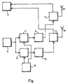
- the desired values of changes of the polarization angles between two TDMA-frames are obtained when the control means 20 delivers to the amplitude modulators 12 and 13 control signals which are proportional respectively to the sinus and cosinus of an angle which for each new TDMA-frame is changed to an extent which equals the desired change of the polarization angle.
- Time multiplex mobile telephony systems are also found in which the signal sequences are relatively long in comparison with the signal sequences of the GSM-system.
- systems are found in North America in which the interleaving depth is equal to two between the signal sequences, but where interleaving also occurs within each signal sequence.
- each information frame is divided into two parts, whereafter the second part of one frame and the first part of the next frame are transmitted in the same signal sequence.
- the interleaving depth is equal to four, the contents of said second and first parts are divided into two parts prior to transmission, whereafter these combined four parts are spread appropriately within the signal sequence. For instance, if half the signal sequence is lost, only a quarter of the two original information frames will be lost.
- each of the aforesaid four parts are transmitted with a respective polarization direction.
- four different polarization directions are needed in order for all parts of a signal sequence to be transmitted with different polarization directions.
- the number of different polarization directions shall be equal to the number of interleaving levels. This enables information parts to be transmitted with different polarization directions from one and the same information frame.
- the illustrated arrangement can be modified in several ways.
- separate antennas can be used for transmitting and receiving purposes.
- the fixed station may also be equipped with more than two antennas for transmission purposes, wherein all antennas have different polarization directions.
- Each of the antennas is supplied with signals which have mutually different amplitudes.
Description
- The present invention relates to a method for reducing in a digital time-multiplex mobile telephony system the risk of poor reception when transmitting from a fixed station to a mobile station, as a result of reflection of transmitted signals by different objects, wherein each information frame to be transmitted is divided into a plurality of information parts determined by the number of interleaving levels.
- In the case of radio communication between two stations of which at least one is moveable, so-called Rayleigh fading will often occur. This is due to reflection of the radio signals against different objects, such that several signals which have travelled along different paths will mutually coact or counteract one another at different points. Consequently, the strengths of the signals received will vary in accordance with the mutual positions of the transmitter antenna and the receiver antenna, and may temporarily drop to zero or to a value in the vicinity of zero. Reflection of the signals also causes the direction of polarization of the transmitted radio wave to change in accordance with the form of the reflective object. The rate at which signal strength varies is proportional to the relative speed between the stations. On those occasions when the relative speed is zero, the connection may be broken because the input signal of the receiver in one station is excessively low. For example, this can occur in a mobile telephony system when a connection is established from a vehicle which remains stationary in a geographic location where the received signal strength is very low, or when the vehicle moves slowly in such a location. Such locations are called zero points.
- It is known that poor reception due to the occurrence of zero points can be avoided with the aid of so-called space diversity. In this case, a station, for example a base station in a mobile telephony system, is equipped with two receiver antennas which are spaced appropriately apart. A so-called diversity effect is obtained in the fixed station with the aid of a suitable addition function of two received signals. This is based on the assumption that the probability of both antennas being located simultaneously in a zero point is small.
- In time multiplex mobile telephony systems with digital modulation, the information from each subscriber is divided into information sections, called information frames. These frames are normally called speech frames in speech transmission. In the case of GSM-type systems (Groupe Speciale Mobile), the information in each such frame is divided into a specific number of signal sequences (bursts), which together with corresponding signal sequences from other subscribers form time slots in a plurality of mutually sequential TDMA-frames. Thus, each TDMA-frame includes information parts, i.e. signal sequences, from several subscribers. The number of signal sequences into which the information contained in each information frame is divided is determined by the number of so-called interleaving levels, the so-called interleaving depth in the channel code. In the GSM-system, the interleaving depth is equal to eight, i.e. the content of each information frame is divided into eight signal sequences.
- It is known to apply frequency-jump transmission in GSM-type systems. In this case, different TDMA-frames are transmitted on different frequencies. This method is based on the fact that the positions of the zero points are frequency-dependent and that the probability of a geographic location being a zero point at more than one frequency is small when the frequency jump is sufficiently large. The method is suitable for GSM-type systems with deep interleaving.
- In radio systems having small cell radii and therewith relatively short transmission distances, for example PCN-type systems (Personal Communication Network), a frequency jump does not provide any marked improvement of the reception at zero points. This is due to small time dispersion, i.e. there is a small time difference between signals that are received subsequent to having travelled through different paths to the receiver. Frequency jumps of reasonable magnitudes do not change the geographic positions of the zero points to any appreciable extent in such systems.
- GB-A-222/820 discloses a polarization diversity radio communication system.
- The object of the present invention is to provide a method of the kind defined in the introduction which will avoid the problems caused by poor reception that results from the occurrence of so-called zero points, both in stations equipped with only one antenna and also in systems having relatively small cell radii and therewith relatively small time dispersion. This object is achieved by transmitting from the fixed station with a polarization direction which is changed stepwise between different parts of the information transmitted. As a result, the fading pattern around the receiver antenna of the mobile station will be changed in time and any occurrent zero points will move in the geography, even in systems having small time dispersion, for example in city environments. The polarization direction is changed for each new TDMA-frame in a GSM-system. It is therefore improbable that more than one signal sequence will be lost for a given subscriber.
- The characteristic features of the invention are set forth in the following Claims.
- The invention will now be described in more detail with reference to the accompanying drawing, which illustrates an exemplifying embodiment of an arrangement included in the fixed station for the purpose of carrying out the inventive method.
- The illustrated arrangement uses two antennas both for receiving and transmitting. When receiving in the fixed station, diversity reception is applied, although this is not a necessary feature of the present invention. The antennas are referenced 18 and 19 and, when receiving, signals received by the receivers are conducted to a receiving
device 11, via twoduplex filters transmission device 10, and are applied to two branches. The signals in the two branches are each conducted to arespective antenna 18, 19 via arespective amplitude modulator respective power amplifier respective duplex filter - The antennas are oriented so as to have different polarization directions therebetween. For example, the polarization directions may differ by 90 degrees in relation to one another.
- The amplitude modulators are controlled by signals from a control means 20 and modulate the signals to power amplifiers so that the powers delivered to the two antennas are changed in relation to each other. This results in a change in the polarization direction of the resultant output signal. In GSM-type radio communication systems with short signal sequences, the amplitude should not be changed during an ongoing signal sequence. This is because such systems do not include an equalizer which can adapt to such changes. In the case of the GSM-system, the polarization angle of the resultant signal is therefore changed after each TDMA-frame, by changing the amplitudes of the signals to the two antennas stepwise after each TDMA-frame. The changes are preferably made so that the polarization angle is changed 180/N degrees for each new TDMA-frame, where N is the interleaving depth in the channel code. This means that N is equal to the number of signal sequences into which each information frame from a subscriber is divided. If the resultant polarization direction from the antennas is changed in this way, it is probable that at most only one signal sequence will be lost, even though the mobile station should be situated in a zero point for a given polarization direction, since the zero point will move for each new signal sequence.
- It can be mentioned by way of example that in a GSM-system in which the interleaving depth is equal to eight, each information frame is divided into eight parts which are distributed on eight signal sequences. If each signal sequence has its own polarization angle, it is improbable that two such sequences will give rise to a zero point on the receiver. Transmission is therefore effected at eight different polarization angles. These angles may, for instance, be 0, 22.5, 45, 67.5, 90 degrees, etc. A single lost part of one information frame can be reconstructed in the receiver, with the aid of remaining signal sequences and a so-called error correcting code.
- The desired values of changes of the polarization angles between two TDMA-frames are obtained when the control means 20 delivers to the
amplitude modulators - Time multiplex mobile telephony systems are also found in which the signal sequences are relatively long in comparison with the signal sequences of the GSM-system. For example, systems are found in North America in which the interleaving depth is equal to two between the signal sequences, but where interleaving also occurs within each signal sequence. For example, each information frame is divided into two parts, whereafter the second part of one frame and the first part of the next frame are transmitted in the same signal sequence. When the interleaving depth is equal to four, the contents of said second and first parts are divided into two parts prior to transmission, whereafter these combined four parts are spread appropriately within the signal sequence. For instance, if half the signal sequence is lost, only a quarter of the two original information frames will be lost.
- Systems of this kind use equalizers which adapt to changes in the channel during a signal sequence. This change may be due, for instance, to movement of a mobile station. The polarization direction can then also be rotated during the signal sequences instead of solely between different TDMA-frames. According to the invention, each of the aforesaid four parts are transmitted with a respective polarization direction. In this case, four different polarization directions are needed in order for all parts of a signal sequence to be transmitted with different polarization directions. Generally, the number of different polarization directions shall be equal to the number of interleaving levels. This enables information parts to be transmitted with different polarization directions from one and the same information frame.
- It will be understood that the illustrated arrangement can be modified in several ways. For example, separate antennas can be used for transmitting and receiving purposes. It will be understood from the aforegoing that it is not absolutely necessary to use two antennas for receiving signals in the fixed station. The fixed station may also be equipped with more than two antennas for transmission purposes, wherein all antennas have different polarization directions. Each of the antennas is supplied with signals which have mutually different amplitudes.
Claims (4)
- A method for reducing in a digital time multiplex mobile telephony system the risk of poor reception as a result of reflection of transmitted signals by different objects, when transmitting from a fixed station to a mobile station, wherein each information frame to be transmitted is divided into a number of information parts determined by the number of interleaving levels, characterized in that transmission from the fixed station is effected with a polarization direction which is changed stepwise in a manner such that all information parts from one and the same information frame will be transmitted in mutually different polarization directions; and in that the number of different polarization directions coincides with the number of interleaving levels.
- A method according to Claim 1, characterized in that when transmitting, the aforesaid information parts from one and the same information frame are included in a respective TDMA-frame; and in that the polarization direction is changed after each TDMA-frame.
- A method according to Claim 1, characterized in that the polarization direction is changed after each transmitted information part.
- A method according to any one of Claims 1, 2 and 3, characterized in that transmission in the fixed station is effected from at least two antennas (18, 19) which are oriented with mutually different polarization directions and each of which is supplied with respective signals which have mutually the same frequency and mutually the same information content but the amplitudes of which are modulated in a manner such that the polarization direction of a resultant output signal from the antennas is changed in the aforegiven manner.
Applications Claiming Priority (2)
| Application Number | Priority Date | Filing Date | Title |
|---|---|---|---|
| SE9003197A SE467385B (en) | 1990-10-05 | 1990-10-05 | PROCEDURE TO REDUCE RISK BEFORE POSSIBLE RECEIVING IN A MOBILE PHONE SYSTEM |
| SE9003197 | 1990-10-05 |
Publications (2)
| Publication Number | Publication Date |
|---|---|
| EP0479744A1 EP0479744A1 (en) | 1992-04-08 |
| EP0479744B1 true EP0479744B1 (en) | 1995-05-10 |
Family
ID=20380579
Family Applications (1)
| Application Number | Title | Priority Date | Filing Date |
|---|---|---|---|
| EP91850215A Expired - Lifetime EP0479744B1 (en) | 1990-10-05 | 1991-09-05 | A method for reducing the risk of poor reception in a mobile telephony system |
Country Status (7)
| Country | Link |
|---|---|
| US (1) | US5267268A (en) |
| EP (1) | EP0479744B1 (en) |
| JP (1) | JP3151247B2 (en) |
| AU (1) | AU649271B2 (en) |
| CA (1) | CA2051738C (en) |
| DE (1) | DE69109601T2 (en) |
| SE (1) | SE467385B (en) |
Families Citing this family (10)
| Publication number | Priority date | Publication date | Assignee | Title |
|---|---|---|---|---|
| DE19546599C2 (en) * | 1995-12-13 | 1999-07-29 | Siemens Ag | Sending device |
| DE59605654D1 (en) * | 1996-09-20 | 2000-08-31 | Siemens Ag | Polarization diversity system for mobile communication with adaptive design of the radiation pattern |
| US6181920B1 (en) | 1997-10-20 | 2001-01-30 | Ericsson Inc. | Transmitter that selectively polarizes a radio wave |
| EP1169750A4 (en) * | 2000-01-21 | 2004-12-08 | Motorola Inc | System and method for wireless communication using polarization diversity |
| EP1191710B1 (en) * | 2000-09-20 | 2004-12-08 | Lucent Technologies Inc. | Radio system, antenna arrangement and polarization modulator for generating a transmit signal with changing polarization |
| EP1303059B1 (en) * | 2001-10-09 | 2006-08-23 | Lucent Technologies Inc. | Method and apparatus for transmission diversity in wireless telecomunication systems providing antenna and/or polarisation hopping sequences |
| JP2008271443A (en) * | 2007-04-24 | 2008-11-06 | Brother Ind Ltd | Radio transmitter and radio communication equipment |
| US8162465B2 (en) | 2008-11-20 | 2012-04-24 | Xerox Corporation | Waste phase change ink recycling |
| US8147049B2 (en) | 2008-11-20 | 2012-04-03 | Xerox Corporation | Waste phase change ink recycling |
| JP6228108B2 (en) * | 2014-12-18 | 2017-11-08 | 株式会社日立製作所 | Wireless communication system |
Family Cites Families (5)
| Publication number | Priority date | Publication date | Assignee | Title |
|---|---|---|---|---|
| FR2215759A1 (en) * | 1973-01-26 | 1974-08-23 | Lafonta Paul | |
| JPS609239A (en) * | 1983-06-27 | 1985-01-18 | Nippon Telegr & Teleph Corp <Ntt> | Code transmission system |
| FR2609224B1 (en) * | 1986-12-30 | 1989-04-07 | Thomson Csf | DEVICE AND METHOD FOR TRANSMITTING AND / OR ACQUIRING DATA USING TWO CROSS POLARIZATIONS OF AN ELECTROMAGNETIC WAVE AND MAGNETIC RECORDING DEVICE |
| JPH0744492B2 (en) * | 1988-06-15 | 1995-05-15 | 松下電工株式会社 | Polarization diversity wireless communication system |
| JPH0624342B2 (en) * | 1988-06-29 | 1994-03-30 | 日本電気株式会社 | Uplink cross polarization compensator |
-
1990
- 1990-10-05 SE SE9003197A patent/SE467385B/en not_active IP Right Cessation
-
1991
- 1991-09-05 DE DE69109601T patent/DE69109601T2/en not_active Expired - Lifetime
- 1991-09-05 EP EP91850215A patent/EP0479744B1/en not_active Expired - Lifetime
- 1991-09-18 CA CA002051738A patent/CA2051738C/en not_active Expired - Fee Related
- 1991-10-04 US US07/771,216 patent/US5267268A/en not_active Expired - Lifetime
- 1991-10-04 JP JP25805691A patent/JP3151247B2/en not_active Expired - Fee Related
- 1991-10-04 AU AU85637/91A patent/AU649271B2/en not_active Ceased
Also Published As
| Publication number | Publication date |
|---|---|
| SE9003197D0 (en) | 1990-10-05 |
| DE69109601T2 (en) | 1995-09-28 |
| AU649271B2 (en) | 1994-05-19 |
| SE9003197L (en) | 1992-04-06 |
| CA2051738A1 (en) | 1992-04-06 |
| JPH04260227A (en) | 1992-09-16 |
| DE69109601D1 (en) | 1995-06-14 |
| JP3151247B2 (en) | 2001-04-03 |
| SE467385B (en) | 1992-07-06 |
| AU8563791A (en) | 1993-04-29 |
| EP0479744A1 (en) | 1992-04-08 |
| CA2051738C (en) | 1999-11-16 |
| US5267268A (en) | 1993-11-30 |
Similar Documents
| Publication | Publication Date | Title |
|---|---|---|
| AU688878B2 (en) | Method for realizing frequency hopping and a base station equipment | |
| US7929922B2 (en) | Radio communication system, a transmitter and a receiver | |
| US5329548A (en) | Base station for a frequency hopping TDMA radio communication system | |
| EP1033819B1 (en) | Base station device and transmission method | |
| JPS6242537B2 (en) | ||
| WO1995034997A2 (en) | Diversity combining for antennas | |
| EP0479744B1 (en) | A method for reducing the risk of poor reception in a mobile telephony system | |
| EP0419429A1 (en) | Method of reducing the risk for poor reception in a time multiplexed radio communication system | |
| EP0761045B1 (en) | A method for improving connection quality in a cellular radio system, and a base station | |
| GB2057819A (en) | Digital radio system | |
| EP0976277A2 (en) | Method of facilitating transmission level measurement, and base station | |
| US6704345B1 (en) | Transmission/reception apparatus and transmission/reception method | |
| EP0937366B1 (en) | Method of combining several signals, and base station | |
| JPS6328145A (en) | Radio communication system | |
| FI106833B (en) | The connection method and the transceiver | |
| WO2002003641A1 (en) | Cofdm transmitter with diversity and time delay | |
| JPH07162332A (en) | Hot stand-by transmitter-receiver | |
| JPH044620A (en) | Transmission power controller | |
| JPH03274922A (en) | Transmission power control system | |
| JPS58184837A (en) | Mobile radio diversity system |
Legal Events
| Date | Code | Title | Description |
|---|---|---|---|
| PUAI | Public reference made under article 153(3) epc to a published international application that has entered the european phase |
Free format text: ORIGINAL CODE: 0009012 |
|
| AK | Designated contracting states |
Kind code of ref document: A1 Designated state(s): DE FR GB IT |
|
| 17P | Request for examination filed |
Effective date: 19920901 |
|
| 17Q | First examination report despatched |
Effective date: 19940914 |
|
| GRAA | (expected) grant |
Free format text: ORIGINAL CODE: 0009210 |
|
| AK | Designated contracting states |
Kind code of ref document: B1 Designated state(s): DE FR GB IT |
|
| REF | Corresponds to: |
Ref document number: 69109601 Country of ref document: DE Date of ref document: 19950614 |
|
| ITF | It: translation for a ep patent filed |
Owner name: FUMERO BREVETTI S.N.C. |
|
| ET | Fr: translation filed | ||
| PLBE | No opposition filed within time limit |
Free format text: ORIGINAL CODE: 0009261 |
|
| STAA | Information on the status of an ep patent application or granted ep patent |
Free format text: STATUS: NO OPPOSITION FILED WITHIN TIME LIMIT |
|
| 26N | No opposition filed | ||
| REG | Reference to a national code |
Ref country code: GB Ref legal event code: IF02 |
|
| PGFP | Annual fee paid to national office [announced via postgrant information from national office to epo] |
Ref country code: GB Payment date: 20020828 Year of fee payment: 12 |
|
| PG25 | Lapsed in a contracting state [announced via postgrant information from national office to epo] |
Ref country code: GB Free format text: LAPSE BECAUSE OF NON-PAYMENT OF DUE FEES Effective date: 20030905 |
|
| GBPC | Gb: european patent ceased through non-payment of renewal fee | ||
| PG25 | Lapsed in a contracting state [announced via postgrant information from national office to epo] |
Ref country code: IT Free format text: LAPSE BECAUSE OF NON-PAYMENT OF DUE FEES;WARNING: LAPSES OF ITALIAN PATENTS WITH EFFECTIVE DATE BEFORE 2007 MAY HAVE OCCURRED AT ANY TIME BEFORE 2007. THE CORRECT EFFECTIVE DATE MAY BE DIFFERENT FROM THE ONE RECORDED. Effective date: 20050905 |
|
| PGFP | Annual fee paid to national office [announced via postgrant information from national office to epo] |
Ref country code: FR Payment date: 20100930 Year of fee payment: 20 |
|
| PGFP | Annual fee paid to national office [announced via postgrant information from national office to epo] |
Ref country code: DE Payment date: 20100929 Year of fee payment: 20 |
|
| REG | Reference to a national code |
Ref country code: DE Ref legal event code: R071 Ref document number: 69109601 Country of ref document: DE |
|
| REG | Reference to a national code |
Ref country code: DE Ref legal event code: R071 Ref document number: 69109601 Country of ref document: DE |
|
| PG25 | Lapsed in a contracting state [announced via postgrant information from national office to epo] |
Ref country code: DE Free format text: LAPSE BECAUSE OF EXPIRATION OF PROTECTION Effective date: 20110906 |