EP0479742B1 - Air intake supressor - Google Patents
Air intake supressor Download PDFInfo
- Publication number
- EP0479742B1 EP0479742B1 EP91850195A EP91850195A EP0479742B1 EP 0479742 B1 EP0479742 B1 EP 0479742B1 EP 91850195 A EP91850195 A EP 91850195A EP 91850195 A EP91850195 A EP 91850195A EP 0479742 B1 EP0479742 B1 EP 0479742B1
- Authority
- EP
- European Patent Office
- Prior art keywords
- mixer
- cover
- propeller
- air intake
- diameter
- Prior art date
- Legal status (The legal status is an assumption and is not a legal conclusion. Google has not performed a legal analysis and makes no representation as to the accuracy of the status listed.)
- Expired - Lifetime
Links
- 239000007788 liquid Substances 0.000 abstract description 14
- 230000003467 diminishing effect Effects 0.000 abstract 1
- 239000008240 homogeneous mixture Substances 0.000 description 1
- 238000004519 manufacturing process Methods 0.000 description 1
- 239000000463 material Substances 0.000 description 1
- 238000004062 sedimentation Methods 0.000 description 1
- 239000002351 wastewater Substances 0.000 description 1
- XLYOFNOQVPJJNP-UHFFFAOYSA-N water Substances O XLYOFNOQVPJJNP-UHFFFAOYSA-N 0.000 description 1
Images
Classifications
-
- C—CHEMISTRY; METALLURGY
- C02—TREATMENT OF WATER, WASTE WATER, SEWAGE, OR SLUDGE
- C02F—TREATMENT OF WATER, WASTE WATER, SEWAGE, OR SLUDGE
- C02F3/00—Biological treatment of water, waste water, or sewage
- C02F3/02—Aerobic processes
- C02F3/12—Activated sludge processes
- C02F3/1278—Provisions for mixing or aeration of the mixed liquor
- C02F3/1284—Mixing devices
-
- B—PERFORMING OPERATIONS; TRANSPORTING
- B01—PHYSICAL OR CHEMICAL PROCESSES OR APPARATUS IN GENERAL
- B01F—MIXING, e.g. DISSOLVING, EMULSIFYING OR DISPERSING
- B01F27/00—Mixers with rotary stirring devices in fixed receptacles; Kneaders
- B01F27/25—Mixers with both stirrer and drive unit submerged in the material being mixed
-
- Y—GENERAL TAGGING OF NEW TECHNOLOGICAL DEVELOPMENTS; GENERAL TAGGING OF CROSS-SECTIONAL TECHNOLOGIES SPANNING OVER SEVERAL SECTIONS OF THE IPC; TECHNICAL SUBJECTS COVERED BY FORMER USPC CROSS-REFERENCE ART COLLECTIONS [XRACs] AND DIGESTS
- Y02—TECHNOLOGIES OR APPLICATIONS FOR MITIGATION OR ADAPTATION AGAINST CLIMATE CHANGE
- Y02W—CLIMATE CHANGE MITIGATION TECHNOLOGIES RELATED TO WASTEWATER TREATMENT OR WASTE MANAGEMENT
- Y02W10/00—Technologies for wastewater treatment
- Y02W10/10—Biological treatment of water, waste water, or sewage
Definitions
- the invention concerns a device to limit the amount of air intake into a rotating mixer operating beneath a liquid surface.
- Mixers of this type are used for instance in waste water and in various types of industrial process liquids to maintain a homogeneous mixture and to prevent sedimentation.
- the mixer is then placed at a distance below the liquid surface directed so that a flow suitable for the mixing vessel is obtained.
- the so-called submersible mixer is common today.
- This mixer is comprised of a hydraulic part having a propeller and an attached driving unit.
- the big advantage with such a mixer is that it is easier to place the mixer advantageously as there is no long shaft connected to a driving unit outside the tank.
- a stand for the submersible mixer onto which is mounted 2 and electric motor which drives 3, a shaft and 4, propeller. Also shown, 5, a propeller shroud; 6, the cover having front and back ends, 6a and 6b resp; 7, a sliding bracket to guide the mixer up and down; 8, a guide bar; 9, the tank bottom; and 10, the liquid surface.
- the mixer which preferably is arranged horizontally, constitutes a single unit which may be moved vertically along a guide.
- the distance between the mixer and the tank bottom 9 is not allowed to be too short to secure a good result and therefore the problem with a too short a distance between the mixer and the liquid surface 10 often arises.
- a cover 6 is arranged below the liquid surface just above the mixer.
- the cover is so designed that its front edge is situated 0,5 - 0,7 times the propeller diameter ahead of the propeller area, while its back edge is situated about twice the propeller diameter behind the area of the propeller.
- the width of the propeller is about twice the propeller diameter. These measures are approximative and may vary in dependance of the type of liquid, the distance to the liquid level etc.
- the cover 6 should be arranged as near the propeller 4 or its jetring as possible without considerably limiting the inlet area and is according to first embodiment, in parallel with the driving shaft 3 (horizontally). According to a preferred embodiment the cover 6 is inclined 5 to 15 degrees, preferably 8 - 12 degrees with regard to the horizontal plane. This gives a better efficiency as the cover then represents less hinderance for the flow. In spite of that, there is very little risk for air intake even if the water level goes down even to the upper edge of the cover.
- the cover is normally designed plane, but even other more or less curved embodiments are possible.
- the great advantage with the invention is thus that the cover is mounted on the mixer which means that it is always placed correctly, independent of where the mixer is operating.
- the inclination of the cover according to the preferred embodiment that a good efficiency is maintained and that the risk for air intake is minimized even when the mixer is operating near the liquid surface.
Landscapes
- Life Sciences & Earth Sciences (AREA)
- Chemical & Material Sciences (AREA)
- Engineering & Computer Science (AREA)
- Biodiversity & Conservation Biology (AREA)
- Microbiology (AREA)
- Hydrology & Water Resources (AREA)
- Chemical Kinetics & Catalysis (AREA)
- Environmental & Geological Engineering (AREA)
- Water Supply & Treatment (AREA)
- Organic Chemistry (AREA)
- Mixers Of The Rotary Stirring Type (AREA)
- Mixers With Rotating Receptacles And Mixers With Vibration Mechanisms (AREA)
- Valves And Accessory Devices For Braking Systems (AREA)
- Cylinder Crankcases Of Internal Combustion Engines (AREA)
- Nozzles (AREA)
Abstract
Description
- The invention concerns a device to limit the amount of air intake into a rotating mixer operating beneath a liquid surface.
- Mixers of this type are used for instance in waste water and in various types of industrial process liquids to maintain a homogeneous mixture and to prevent sedimentation. The mixer is then placed at a distance below the liquid surface directed so that a flow suitable for the mixing vessel is obtained.
- The so-called submersible mixer is common today. This mixer is comprised of a hydraulic part having a propeller and an attached driving unit. The big advantage with such a mixer is that it is easier to place the mixer advantageously as there is no long shaft connected to a driving unit outside the tank.
- When operating in shallow tanks where the mixer must be placed near the liquid surface, specific problems arise. The draw that arises around the mixer means that there is a risk for air intake from the liquid surface. This air intake means a worse efficiency and in addition there is a risk for vibration in the mixer which disturbs the flow and causes mechanical strain in the material. These problems occur mainly if the mixer is situated within or near the liquid surface.
- In order to solve the problems it has been suggested to arrange a floating cover on the surface above the mixer. Such a cover can be useful, but the fact that the liquid level often changes means that the result often is insufficient.
- According to the invention, the problem to reduce the risk for air intake to a rotating mixer is solved by a device stated in the following claims.
- The invention is described more closely below with reference to the enclosed drawing.
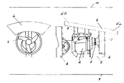
- In the drawing is shown 1, a stand for the submersible mixer onto which is mounted 2, and electric motor which drives 3, a shaft and 4, propeller. Also shown, 5, a propeller shroud; 6, the cover having front and back ends, 6a and 6b resp; 7, a sliding bracket to guide the mixer up and down; 8, a guide bar; 9, the tank bottom; and 10, the liquid surface.
- The mixer, which preferably is arranged horizontally, constitutes a single unit which may be moved vertically along a guide. The distance between the mixer and the
tank bottom 9 is not allowed to be too short to secure a good result and therefore the problem with a too short a distance between the mixer and theliquid surface 10 often arises. - According to the invention, a
cover 6 is arranged below the liquid surface just above the mixer. The cover is so designed that its front edge is situated 0,5 - 0,7 times the propeller diameter ahead of the propeller area, while its back edge is situated about twice the propeller diameter behind the area of the propeller. - The width of the propeller is about twice the propeller diameter. These measures are approximative and may vary in dependance of the type of liquid, the distance to the liquid level etc.
- The
cover 6 should be arranged as near the propeller 4 or its jetring as possible without considerably limiting the inlet area and is according to first embodiment, in parallel with the driving shaft 3 (horizontally). According to a preferred embodiment thecover 6 is inclined 5 to 15 degrees, preferably 8 - 12 degrees with regard to the horizontal plane. This gives a better efficiency as the cover then represents less hinderance for the flow. In spite of that, there is very little risk for air intake even if the water level goes down even to the upper edge of the cover. - The cover is normally designed plane, but even other more or less curved embodiments are possible.
- The great advantage with the invention is thus that the cover is mounted on the mixer which means that it is always placed correctly, independent of where the mixer is operating. In addition the inclination of the cover according to the preferred embodiment that a good efficiency is maintained and that the risk for air intake is minimized even when the mixer is operating near the liquid surface.
Claims (4)
- Apparatus comprising a submersible mixer having a submersible motor and a cover, which may be designed plane or curved and arranged directly on the mixer, characterized in that the cover (6) has its front end (6a) within the area immediately above and possibly ahead of the propeller (4) and its back end (6b) within the area above the motor (2).
- A device according to claim 1, characterized in that the cover (6) forms an angle of 5 - 15 degrees preferably 8 - 12 degrees with the driving shaft (3), the front end (6a) being closer to the shaft (3) that the back end (6b).
- A device according to claim 1, characterized in that the cover (6) has a width of twice the diameter of the propeller (4) and a length 2 - 3 times said diameter.
- A device according to claim 1, characterized in that the front end (6a) of the cover is situated 0,5 - 0,7 times the propeller diameter ahead of the area of the propeller (4), while its back edge (6b) is situated about twice the propeller diameter behind the area of the propeller (4).
Applications Claiming Priority (2)
| Application Number | Priority Date | Filing Date | Title |
|---|---|---|---|
| SE9003035 | 1990-09-25 | ||
| SE9003035A SE466737B (en) | 1990-09-25 | 1990-09-25 | AIR BUCKING LIMITER PROVIDES A STIRRATOR PROVIDED UNDER A WATER SHUTTER WITH A PROPELLER ON A MAJOR HORIZONTALLY AXED |
Publications (2)
| Publication Number | Publication Date |
|---|---|
| EP0479742A1 EP0479742A1 (en) | 1992-04-08 |
| EP0479742B1 true EP0479742B1 (en) | 1995-05-03 |
Family
ID=20380436
Family Applications (1)
| Application Number | Title | Priority Date | Filing Date |
|---|---|---|---|
| EP91850195A Expired - Lifetime EP0479742B1 (en) | 1990-09-25 | 1991-08-14 | Air intake supressor |
Country Status (7)
| Country | Link |
|---|---|
| US (1) | US5174652A (en) |
| EP (1) | EP0479742B1 (en) |
| JP (1) | JPH06102137B2 (en) |
| AT (1) | ATE122026T1 (en) |
| AU (1) | AU641543B2 (en) |
| DE (1) | DE69109431T2 (en) |
| SE (1) | SE466737B (en) |
Families Citing this family (2)
| Publication number | Priority date | Publication date | Assignee | Title |
|---|---|---|---|---|
| JP5084664B2 (en) * | 2008-08-19 | 2012-11-28 | 株式会社鶴見製作所 | Horizontal submersible electric mixer |
| EP2671350A4 (en) | 2011-02-01 | 2014-12-03 | Timeplay Entertainment Corp | SYSTEMS AND METHODS FOR INTERACTIVE EXPERIENCES, AND CORRESPONDING CONTROL DEVICES |
Family Cites Families (9)
| Publication number | Priority date | Publication date | Assignee | Title |
|---|---|---|---|---|
| FR367664A (en) * | 1906-06-09 | 1906-11-07 | Albert Lespagnol | Endless wire for sawing stones, marbles, granites, porphyries, ores, slates, etc., using a pulverized wearing or lapping body and water |
| US1226400A (en) * | 1916-09-09 | 1917-05-15 | Sidney A Smith | Raffle-plate for propeller-wheels. |
| US2078179A (en) * | 1935-04-15 | 1937-04-20 | Johnson Brothers Engineering C | Trolling plate |
| DE1457121C3 (en) * | 1965-05-29 | 1974-01-17 | Passavant-Werke Michelbacher Huette, 6209 Aarbergen | Repository for unilaterally driven horizontal-axis aeration rotors for wastewater treatment |
| DE2446086A1 (en) * | 1974-09-26 | 1976-04-08 | Weissenhorner Manfred | Mixing and dispersion of sewage - using mixing element in channel or storage parallel with or across flow |
| US4240990A (en) * | 1979-04-10 | 1980-12-23 | Aeration Industries, Inc. | Aeration propeller and apparatus |
| US4431597A (en) * | 1982-09-29 | 1984-02-14 | Air-O-Lator Corporation | Horizontal mixing aerator |
| US4581182A (en) * | 1985-02-21 | 1986-04-08 | Air-O-Lator Corporation | Submersible mixer with air injection |
| US4671872A (en) * | 1986-03-18 | 1987-06-09 | Air-O-Lator Corporation | Aerator mast with azimuth lock and bottom stop |
-
1990
- 1990-09-25 SE SE9003035A patent/SE466737B/en not_active IP Right Cessation
-
1991
- 1991-08-14 DE DE69109431T patent/DE69109431T2/en not_active Expired - Fee Related
- 1991-08-14 AT AT91850195T patent/ATE122026T1/en not_active IP Right Cessation
- 1991-08-14 EP EP91850195A patent/EP0479742B1/en not_active Expired - Lifetime
- 1991-08-27 JP JP3215466A patent/JPH06102137B2/en not_active Expired - Fee Related
- 1991-09-02 AU AU83612/91A patent/AU641543B2/en not_active Ceased
- 1991-09-24 US US07/766,236 patent/US5174652A/en not_active Expired - Lifetime
Also Published As
| Publication number | Publication date |
|---|---|
| AU8361291A (en) | 1992-04-02 |
| SE9003035D0 (en) | 1990-09-25 |
| ATE122026T1 (en) | 1995-05-15 |
| SE466737B (en) | 1992-03-30 |
| US5174652A (en) | 1992-12-29 |
| EP0479742A1 (en) | 1992-04-08 |
| DE69109431D1 (en) | 1995-06-08 |
| DE69109431T2 (en) | 1996-01-18 |
| JPH04247229A (en) | 1992-09-03 |
| JPH06102137B2 (en) | 1994-12-14 |
| AU641543B2 (en) | 1993-09-23 |
Similar Documents
| Publication | Publication Date | Title |
|---|---|---|
| GB2082077A (en) | Surface aeration | |
| KR920000369A (en) | agitator | |
| US6276670B1 (en) | Combined mixer-aerator | |
| US4954295A (en) | Propeller aerator with peripheral injection of fluid and method of using the aerator | |
| GB1583583A (en) | Effluent aerator | |
| KR890002281B1 (en) | Apparatus for mixing gas with liquid | |
| NL7605028A (en) | Mixing or flotation appts - has an impeller rotated on a vertical shaft below apertured, conical shroud | |
| ATE82148T1 (en) | SETTLEMENT TANK FOR AN ACTIVATED SLUDGE WASTEWATER SUSPENSION. | |
| EP0479742A1 (en) | Air intake supressor | |
| CA1126257A (en) | Recirculating slurry mixer with azimuth adjustable feed propeller and scraper blades | |
| JPS55112388A (en) | Float separator | |
| GB1221022A (en) | Treatment of a liquid by means of a gaseous fluid | |
| GB1569577A (en) | Apparatus for mixing gases into liquids which tend to froth | |
| US4721392A (en) | Method and a device for installation of a mixer | |
| US6079864A (en) | Horizontal flow generation system | |
| JP4754586B2 (en) | Aeration stirrer | |
| CN1836792A (en) | Liner material supply apparatus | |
| JPS6242730A (en) | Mount apparatus used in liquid tank | |
| ATE90408T1 (en) | DEVICE FOR SUCTION OF LIQUIDS. | |
| JPS6327773Y2 (en) | ||
| CA2054044C (en) | Fluid mixer | |
| US5634717A (en) | Bulk mixing flow diverter | |
| JPS5621635A (en) | Ventilating and mixing tank | |
| SU1209609A2 (en) | Mechanical aerator | |
| KR880004197Y1 (en) | Mixing apparatus of liquid and gas |
Legal Events
| Date | Code | Title | Description |
|---|---|---|---|
| PUAI | Public reference made under article 153(3) epc to a published international application that has entered the european phase |
Free format text: ORIGINAL CODE: 0009012 |
|
| AK | Designated contracting states |
Kind code of ref document: A1 Designated state(s): AT DE FR GB IT |
|
| 17P | Request for examination filed |
Effective date: 19930211 |
|
| 17Q | First examination report despatched |
Effective date: 19931130 |
|
| GRAA | (expected) grant |
Free format text: ORIGINAL CODE: 0009210 |
|
| AK | Designated contracting states |
Kind code of ref document: B1 Designated state(s): AT DE FR GB IT |
|
| REF | Corresponds to: |
Ref document number: 122026 Country of ref document: AT Date of ref document: 19950515 Kind code of ref document: T |
|
| REF | Corresponds to: |
Ref document number: 69109431 Country of ref document: DE Date of ref document: 19950608 |
|
| ET | Fr: translation filed | ||
| ITF | It: translation for a ep patent filed | ||
| PLBE | No opposition filed within time limit |
Free format text: ORIGINAL CODE: 0009261 |
|
| STAA | Information on the status of an ep patent application or granted ep patent |
Free format text: STATUS: NO OPPOSITION FILED WITHIN TIME LIMIT |
|
| 26N | No opposition filed | ||
| REG | Reference to a national code |
Ref country code: GB Ref legal event code: IF02 |
|
| PGFP | Annual fee paid to national office [announced via postgrant information from national office to epo] |
Ref country code: FR Payment date: 20060731 Year of fee payment: 16 |
|
| PGFP | Annual fee paid to national office [announced via postgrant information from national office to epo] |
Ref country code: GB Payment date: 20060818 Year of fee payment: 16 |
|
| PGFP | Annual fee paid to national office [announced via postgrant information from national office to epo] |
Ref country code: AT Payment date: 20060823 Year of fee payment: 16 |
|
| PGFP | Annual fee paid to national office [announced via postgrant information from national office to epo] |
Ref country code: IT Payment date: 20060831 Year of fee payment: 16 |
|
| PGFP | Annual fee paid to national office [announced via postgrant information from national office to epo] |
Ref country code: DE Payment date: 20060901 Year of fee payment: 16 |
|
| GBPC | Gb: european patent ceased through non-payment of renewal fee |
Effective date: 20070814 |
|
| PG25 | Lapsed in a contracting state [announced via postgrant information from national office to epo] |
Ref country code: AT Free format text: LAPSE BECAUSE OF NON-PAYMENT OF DUE FEES Effective date: 20070814 |
|
| REG | Reference to a national code |
Ref country code: FR Ref legal event code: ST Effective date: 20080430 |
|
| PG25 | Lapsed in a contracting state [announced via postgrant information from national office to epo] |
Ref country code: DE Free format text: LAPSE BECAUSE OF NON-PAYMENT OF DUE FEES Effective date: 20080301 |
|
| PG25 | Lapsed in a contracting state [announced via postgrant information from national office to epo] |
Ref country code: FR Free format text: LAPSE BECAUSE OF NON-PAYMENT OF DUE FEES Effective date: 20070831 |
|
| PG25 | Lapsed in a contracting state [announced via postgrant information from national office to epo] |
Ref country code: GB Free format text: LAPSE BECAUSE OF NON-PAYMENT OF DUE FEES Effective date: 20070814 |
|
| PG25 | Lapsed in a contracting state [announced via postgrant information from national office to epo] |
Ref country code: IT Free format text: LAPSE BECAUSE OF NON-PAYMENT OF DUE FEES Effective date: 20070814 |