EP0479540B1 - Dynamische Drucklagervorrichtung - Google Patents
Dynamische Drucklagervorrichtung Download PDFInfo
- Publication number
- EP0479540B1 EP0479540B1 EP19910308954 EP91308954A EP0479540B1 EP 0479540 B1 EP0479540 B1 EP 0479540B1 EP 19910308954 EP19910308954 EP 19910308954 EP 91308954 A EP91308954 A EP 91308954A EP 0479540 B1 EP0479540 B1 EP 0479540B1
- Authority
- EP
- European Patent Office
- Prior art keywords
- dynamic pressure
- shaft
- thrust receiver
- bearing apparatus
- pressure bearing
- Prior art date
- Legal status (The legal status is an assumption and is not a legal conclusion. Google has not performed a legal analysis and makes no representation as to the accuracy of the status listed.)
- Expired - Lifetime
Links
- 239000012530 fluid Substances 0.000 claims description 7
- 230000002093 peripheral effect Effects 0.000 claims description 5
- 239000004033 plastic Substances 0.000 claims description 3
- 229920003023 plastic Polymers 0.000 claims description 3
- 239000000463 material Substances 0.000 claims 1
- 239000010687 lubricating oil Substances 0.000 description 4
- 230000007423 decrease Effects 0.000 description 2
- 238000005299 abrasion Methods 0.000 description 1
- 238000003754 machining Methods 0.000 description 1
- 238000004519 manufacturing process Methods 0.000 description 1
- 238000005259 measurement Methods 0.000 description 1
- 238000012986 modification Methods 0.000 description 1
- 230000004048 modification Effects 0.000 description 1
- 238000009423 ventilation Methods 0.000 description 1
Images


Classifications
-
- F—MECHANICAL ENGINEERING; LIGHTING; HEATING; WEAPONS; BLASTING
- F16—ENGINEERING ELEMENTS AND UNITS; GENERAL MEASURES FOR PRODUCING AND MAINTAINING EFFECTIVE FUNCTIONING OF MACHINES OR INSTALLATIONS; THERMAL INSULATION IN GENERAL
- F16C—SHAFTS; FLEXIBLE SHAFTS; ELEMENTS OR CRANKSHAFT MECHANISMS; ROTARY BODIES OTHER THAN GEARING ELEMENTS; BEARINGS
- F16C33/00—Parts of bearings; Special methods for making bearings or parts thereof
- F16C33/02—Parts of sliding-contact bearings
- F16C33/04—Brasses; Bushes; Linings
- F16C33/06—Sliding surface mainly made of metal
- F16C33/10—Construction relative to lubrication
- F16C33/1025—Construction relative to lubrication with liquid, e.g. oil, as lubricant
- F16C33/106—Details of distribution or circulation inside the bearings, e.g. details of the bearing surfaces to affect flow or pressure of the liquid
- F16C33/107—Grooves for generating pressure
-
- F—MECHANICAL ENGINEERING; LIGHTING; HEATING; WEAPONS; BLASTING
- F16—ENGINEERING ELEMENTS AND UNITS; GENERAL MEASURES FOR PRODUCING AND MAINTAINING EFFECTIVE FUNCTIONING OF MACHINES OR INSTALLATIONS; THERMAL INSULATION IN GENERAL
- F16C—SHAFTS; FLEXIBLE SHAFTS; ELEMENTS OR CRANKSHAFT MECHANISMS; ROTARY BODIES OTHER THAN GEARING ELEMENTS; BEARINGS
- F16C17/00—Sliding-contact bearings for exclusively rotary movement
- F16C17/04—Sliding-contact bearings for exclusively rotary movement for axial load only
- F16C17/08—Sliding-contact bearings for exclusively rotary movement for axial load only for supporting the end face of a shaft or other member, e.g. footstep bearings
-
- F—MECHANICAL ENGINEERING; LIGHTING; HEATING; WEAPONS; BLASTING
- F16—ENGINEERING ELEMENTS AND UNITS; GENERAL MEASURES FOR PRODUCING AND MAINTAINING EFFECTIVE FUNCTIONING OF MACHINES OR INSTALLATIONS; THERMAL INSULATION IN GENERAL
- F16C—SHAFTS; FLEXIBLE SHAFTS; ELEMENTS OR CRANKSHAFT MECHANISMS; ROTARY BODIES OTHER THAN GEARING ELEMENTS; BEARINGS
- F16C17/00—Sliding-contact bearings for exclusively rotary movement
- F16C17/10—Sliding-contact bearings for exclusively rotary movement for both radial and axial load
- F16C17/102—Sliding-contact bearings for exclusively rotary movement for both radial and axial load with grooves in the bearing surface to generate hydrodynamic pressure
Definitions
- This invention relates to a dynamic pressure bearing apparatus. and more particularly, to a bearing apparatus suitable for bearings to be used in a rotatry unit such as a rotary polygonal mirror type light deflector in a laser beam printer, a rotary head in a video tape recorder and the like.
- a dynamic pressure bearing apparatus as shown in Fig. 1A.
- a shaft I which rotates while supporting a rotary unit is rotatably mounted into a sleeve 2 in fluid such as lubricating oil.
- a radial surface On the cylindrical surface of the shaft 1 (hereinafter referred to as a radial surface), first shallow grooves of a herringbone shape 4 and 5 are formed.
- a dynamic pressure in a radial direction (a direction directed to an outer periphery from a central axis) occurs.
- a non-contact state between the shaft 1 and the sleeve 2 is maintained with respect to the radial direction.
- a distribution profile of the dynamic pressure in the radial direction is illustrated in Fig. 1B.
- a bottom surface of the sleeve 2 opposed to the end surface 6 of the shaft 1 is defined by an insert member 8 fitted into a bottom recess of the sleeve 2.
- On the surface of the insert member 8, a second shallow groove 9 of a spiral shape is formed so that a dynamic pressure in a thrust direction occurs when the shaft 1 is rotated.
- a non-contact state is maintained between the shaft 1 and the sleeve 2.
- a distribution profile of the dynamic pressure in the thrust direction is illustrated in Fig. 1C.
- An inner groove 10 is formed in an inner side wall of the sleeve 2 near an opening end.
- a third shallow groove 11 of a spiral shape is formed on a portion of the radial surface of the shaft 1 located nearer to the opening end than the inner groove 10.
- the degree of squareness of the surface of the insert member 8 on which the shallow groove 9 is formed be 2-3 ⁇ m, and that of the end surface 6 of the shaft 1 also be 2-3 ⁇ m, This linear measurement is the difference between the highest and lowest points on the end surface. Therefore, a high precision operation is needed for fabricating the insert member 8 and the sleeve 2, thus making the costs of these components quite high. Further, there is also a problem that it is difficult to make the insert member 8 with plastics, which is very effective to reduce the cost of a dynamic pressure bearing apparatus.
- EP-A-0117873 discloses a dynamic pressure type of fluid bearing device having a housing provided with a bearing hole, a shaft rotatably mounted in the hole, and a thrust bearing member mounted on the end face of the housing, grooves in the surface of either the shaft or the hole, grooves provided in the surface of the member in contact with the shaft, a ventilation groove communicating with the atmosphere and formed on the surface of the member in contact with the housing and lubricating oil provided around the periphery of the grooves.
- the arrangement prevents the lubricating oil flowing out because of variations in the atmospheric pressure.
- An object of the present invention is to provide a dynamic pressure bearing apparatus which prevents a striking of a rotary shaft and generates a sufficient floating force without requiring high precision machining for obtaining a high degree of squareness on the end surface of the shaft and a thrust receiver surface.
- Fig. 1A is a cross-sectional view of a prior art dynamic pressure bearing apparatus.
- Fig. 1B is a representation illustrating a generation of pressure in a radial direction in the dynamic pressure bearing of Fig. 1A.
- Fig. 1C is a representation illustrating a generation of pressure in a thrust direction in the dynamic pressure bearing of Fig. 1A.
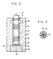
- Fig. 2 is a cross-sectional view of a first embodiment of a dynamic pressure bearing apparatus according to the present invention.
- Fig. 3 is a plan view of an insert member used in the first embodiment of Fig. 2.
- Fig. 4A is a partial view for explaining the operation of the first embodiment of Fig. 2 in a first special case.
- Fig. 4B is a partial view for explaining the operation of the first embodiment of Fig. 2 in a second special case.
- Fig. 5 is a cross-sectional view of of a second embodiment of a dynamic pressure bearing apparatus according to the present invention.
- Fig. 6 is a partial view for explaining the operation of the second embodiment of Fig. 5 in a special case.
- Figs. 2 and 3 show the structure of a first embodiment of the present invention.
- a shaft 21 rotates while supporting a rotary unit such as a polygonal scanner mirror, and the shaft 21 is rotatably mounted into a sleeve 22 through fluid 23 such as lubricating oil.
- fluid 23 such as lubricating oil.
- shallow grooves 24 and 25 of a herringbone shape are formed, and their depths are about 2-20 ⁇ m.
- an insert member 28 is fitted into a bottom recess of the sleeve 22 to form an inner bottom surface.
- a shallow groove 29 of a spiral shape is formed as shown in Fig. 3 its depth being about 2-20 ⁇ m.
- annular groove 30 of a depth of about 0.01 -2mm is formed.
- a further shallow groove 31 is formed of a spiral shape having a depth of about 2-20 ⁇ m.
- the surface of the insert member 28 opposed to the shaft end surface 26 (referred to as a thrust receiver surface 32) has a convex shape, in which a central portion 33 projects toward the shaft end surface 26 to form a crown shape.
- the groove 29 is not formed on the central portion 33 of the thrust receiver surface 32.
- Fig. 3 shows a view of the thrust receiver surface 32 viewed along the shaft 21.
- Fig. 4A shows a case where the surface of an insert member 202 is inclined relative to the inner diameter center axis of a sleeve 201.
- Reference numeral 203 is the second shallow groove, and reference numeral 204 is the thrust receiver surface.
- Fig. 4B shows another case that a shaft end surface 302 is inclined relative to the center axis of a shaft 301, in the structure of the first embodiment.
- the convexity (i.e. the height of the crown) of the center portion of the thrust receiver surface 32 relative to the peripheral portion is about 5-20 ⁇ m. Consequently. the degree of squareness of the insert member 28 and the shaft end surface 26 of the subject invention can be two to four times less accurate compared with a conventional apparatus and still provide an effective fluid bearing.
- the reason that no shallow groove is formed in the center portion 33 of the thrust receiver surface 32 is as follows. Since the thrust receiver surface 32 has a crown shape, the dynamic pressure in the periphery of the thrust receiver surface 32 becomes small, and hence an intensity of a floating force of the shaft 21 decreases. Therefore, during a certain time after starting of the apparatus, or when an external disturbing force is applied in the thrust direction, there is the fear that the shaft end surface 26 will come into contact with the thrust receiver surface 32. To decrease abrasion and wear owing to such contact, a surface area of the center portion where the contact occurs most easily is made as large as possible. For this purpose, no shallow groove is formed in the center portion 33 of the thrust receiver surface 32.
- Fig. 5 shows the structure of a second embodiment of the present invention.
- a shaft end surface 402 of a rotary shaft 401 has a crown shape convexed toward an insert member 403.
- a shallow groove 404 of a spiral shape is formed on a thrust receiver surface 405.
- a center portion 406 of the thrust receiver surface 405 does not have the shallow groove thereon.
- the same reference numerals as those shown in Fig. 2 designate the same members as shown in Fig. 5.
- the thrust receiver surface 405 is formed flat, but the shapes of the shallow groove 404 and the center portion 406 are the same as those shown in Fig. 3.
- the operation of the second embodiment is basically the same as that of the first embodiment.
- Fig. 6 shows a case where the surface of an insert member 501 is inclined relative to the inner diameter center axis of the sleeve 22.
- Reference numeral 502 is a second shallow groove, and reference nimeral 503 is a thrust receiver surface.
- the convexity of the center portion of the shaft end surface 402 relative to the peripheral portion is about 5-20 ⁇ m. Consequently, the degree of squareness of the insert member 403 and the shaft end surface 402 can be two to four times less accurate than a conventional apparatus, similarly to the first embodiment.
- no shallow groove is formed on the center portion of the thrust receiver surface.
- a shallow groove may be formed on the center portion where a floating force in the thrust direction is so sufficient that there is only a small possibility that the shaft end surface will come into contact with the thrust receiver surface while rotating.
- an insert member may be formed with a sleeve body as a unit.
- the shape of a thrust receiver surface on which a spiral shallow groove is formed or a shaft end surface of a rotary shaft opposed to the thrust receiver surface is made convex or crown-shaped, so that the square ends of the thrust receiver surface and the shaft end surface do not have to be precisely machined. Therefore, the fabrication of a dynamic pressure bearing of the present invention becomes easy, and the cost therefor can be lowered. Moreover, it becomes possible to form the thrust receiver surface with plastics.
Landscapes
- Engineering & Computer Science (AREA)
- General Engineering & Computer Science (AREA)
- Mechanical Engineering (AREA)
- Chemical & Material Sciences (AREA)
- Oil, Petroleum & Natural Gas (AREA)
- Physics & Mathematics (AREA)
- Fluid Mechanics (AREA)
- Sliding-Contact Bearings (AREA)
Claims (9)
- Dynamische Drucklagervorrichtung, die aufweist,- eine Welle (21, 301, 401),- ein Gehäuse (22, 201) als Stützlager für die in einer Flüssigkeit sich befindende Welle, das eine der Wellenstirnfläche (26, 302, 402) gegenüber angeordnete Stoßaufnahmefläche (32, 204, 405, 503) hat,- eine erste Generiervorrichtung (29, 203, 404, 502) in Form einer in die Stoßaufnahmefläche eingearbeiteten flachen Nut zur Erzeugung eines dynamischen Druckes in Stoßrichtung und- eine in die Radialfläche der Welle eingearbeitete zweite Generiervorrichtung (24, 25) zur Erzeugung eines Druckes in radialer Richtung,dadurch gekennzeichnet, daß die Stoßaufnahmefläche aus Plastmaterial hergestellt ist, daß einmal die Wellenstirnfläche (402) und die Stoßaufnahmefläche (32, 204) konvexe Form haben, deren höchster Punkt (33) jeweils in der Mitte liegt, und zum anderen die Wellenstirnfläche (26, 302) und die Stoßaufnahmefläche (505, 503) im wesentlichen eben sind.
- Dynamische Drucklagervorrichtung gemäß Anspruch 1, dadurch gekennzeichnet, daß die erste Generiervorrichtung (29, 203, 404, 502) auf einem den Mittelbereich (33) umgebenden peripheren Bereich der Stoßaufnahmefläche vorhanden ist.
- Dynamische Drucklagervorrichtung gemäß Anspruch 2, dadurch gekennzeichnet, daß die auf der Stoßaufnahmefläche (32, 204, 405, 503) vorhandene erste Generiervorrichtung (29, 203, 404, 503) aus einigen radial verlaufenden, flachen Spiralnuten gebildet wird.
- Dynamische Drucklagervorrichtung gemäß Anspruch 2 oder 3, dadurch gekennzeichnet, daß der Höhenunterschied zwischen dem Mittelbereich (33) und dem peripheren Bereich des konvexen Abschnittes 2-20 µm beträgt.
- Dynamische Drucklagervorrichtung gemäß einem der Ansprüche 1-4, dadurch gekennzeichnet, daß die Stoßaufnahmefläche (32, 204) konvexe Form hat.
- Dynamische Drucklagervorrichtung gemäß Anspruch 5, dadurch gekennzeichnet, daß die Achse der konvexen Fläche (204) zur Wellenachse geneigt ist, wobei die Wellenstirnfläche (26) im rechten Winkel zur Wellenachse verläuft.
- Dynamische Drucklagervorrichtung gemäß Anspruch 5, dadurch gekennzeichnet, daß die Achse der konvexen Fläche (32) und die Wellenachse koaxial angeordnet sind und die Wellenstirnfläche (302) eben und zur Wellenachse geneigt ist.
- Dynamische Drucklagervorrichtung gemäß einem der Ansprüche 1-7, dadurch gekennzeichnet, daß die zweite Generiervorrichtung (24, 25) eine flache Pfeilnut aufweist.
- Dynamische Drucklagervorrichtung gemäß einem der Ansprüche 1-8, dadurch gekennzeichnet, daß das Gehäuse einen Mantel (22, 201) und einen Einsatz (28, 202, 403, 501) aufweist und daß die Stoßaufnahmefläche auf der Einsatzoberfläche vorhanden ist.
Applications Claiming Priority (2)
| Application Number | Priority Date | Filing Date | Title |
|---|---|---|---|
| JP26508790A JPH04145215A (ja) | 1990-10-04 | 1990-10-04 | 動圧軸受装置 |
| JP265087/90 | 1990-10-04 |
Publications (3)
| Publication Number | Publication Date |
|---|---|
| EP0479540A2 EP0479540A2 (de) | 1992-04-08 |
| EP0479540A3 EP0479540A3 (en) | 1992-06-03 |
| EP0479540B1 true EP0479540B1 (de) | 1996-06-12 |
Family
ID=17412418
Family Applications (1)
| Application Number | Title | Priority Date | Filing Date |
|---|---|---|---|
| EP19910308954 Expired - Lifetime EP0479540B1 (de) | 1990-10-04 | 1991-09-30 | Dynamische Drucklagervorrichtung |
Country Status (4)
| Country | Link |
|---|---|
| EP (1) | EP0479540B1 (de) |
| JP (1) | JPH04145215A (de) |
| KR (1) | KR0132415B1 (de) |
| DE (1) | DE69120191T2 (de) |
Families Citing this family (5)
| Publication number | Priority date | Publication date | Assignee | Title |
|---|---|---|---|---|
| JP3126880B2 (ja) * | 1994-08-03 | 2001-01-22 | ミネベア株式会社 | モータの軸受装置 |
| KR19980030901A (ko) * | 1996-10-30 | 1998-07-25 | 김광호 | 가변 간극을 갖는 드러스트 베어링 장치 |
| US7492548B2 (en) | 2003-04-24 | 2009-02-17 | Matsushita Electric Industrial Co., Ltd. | Hydrodynamic bearing device and disk rotating apparatus |
| CN100422583C (zh) * | 2003-04-24 | 2008-10-01 | 松下电器产业株式会社 | 流体轴承装置及磁盘旋转装置 |
| DE102006005604B4 (de) * | 2006-02-06 | 2007-11-22 | Minebea Co., Ltd. | Fluiddynamisches Lagersystem |
Family Cites Families (3)
| Publication number | Priority date | Publication date | Assignee | Title |
|---|---|---|---|---|
| DE3066021D1 (en) * | 1979-11-22 | 1984-02-02 | Smiths Industries Plc | Gas-lubricated bearings and method of manufacture |
| EP0117873B1 (de) * | 1982-09-02 | 1986-12-30 | Matsushita Electric Industrial Co., Ltd. | Fluidumlagervorrichtung mit dynamisch aufgebautem druck |
| DE68921256T2 (de) * | 1988-06-28 | 1995-07-06 | Canon Kk | Hydrodynamisches Lager. |
-
1990
- 1990-10-04 JP JP26508790A patent/JPH04145215A/ja active Pending
-
1991
- 1991-09-11 KR KR91015857A patent/KR0132415B1/ko not_active Expired - Fee Related
- 1991-09-30 EP EP19910308954 patent/EP0479540B1/de not_active Expired - Lifetime
- 1991-09-30 DE DE1991620191 patent/DE69120191T2/de not_active Expired - Fee Related
Also Published As
| Publication number | Publication date |
|---|---|
| KR0132415B1 (en) | 1998-04-11 |
| DE69120191T2 (de) | 1996-11-07 |
| EP0479540A3 (en) | 1992-06-03 |
| EP0479540A2 (de) | 1992-04-08 |
| DE69120191D1 (de) | 1996-07-18 |
| JPH04145215A (ja) | 1992-05-19 |
Similar Documents
| Publication | Publication Date | Title |
|---|---|---|
| US5277499A (en) | Dynamic pressure bearing apparatus | |
| US6123460A (en) | Hydrodynamic gas bearing structure and optical deflection scanner comprising the same | |
| US5873657A (en) | Conic fluid bearing and head drum and spindle motor each including the same | |
| US6672767B2 (en) | Dynamic bearing device and motor having the same | |
| US6019516A (en) | Crowned conical bearing | |
| EP0940592B1 (de) | Kombiniertes Lager | |
| EP0479540B1 (de) | Dynamische Drucklagervorrichtung | |
| US7044645B2 (en) | Retainer with rotationally symmetric pockets | |
| KR200145217Y1 (ko) | 공기 동압 베어링 | |
| US5911512A (en) | Fluid bearing apparatus having a uniform dynamic pressure distribution | |
| KR100524431B1 (ko) | 동압베어링장치 | |
| KR19980030389A (ko) | 원추베어링 장치 | |
| EP0349260B1 (de) | Hydrodynamisches Lager | |
| KR19980030392A (ko) | 유체베어링 장치 | |
| US20030123764A1 (en) | Hydrodynamic bearing arrangement for a spindle motor | |
| JPH07113370B2 (ja) | 動圧型流体軸受 | |
| KR100224811B1 (ko) | 반구형 유체 베어링 및 그 제조방법 | |
| JP2780105B2 (ja) | 動圧軸受装置 | |
| KR100238034B1 (ko) | 저어널 베어링 장치 | |
| JPH01105907A (ja) | 回転多面鏡の防音装置 | |
| JPS60208629A (ja) | 光偏向装置 | |
| KR100213883B1 (ko) | 균일 압력 분포를 갖는 동압형 유체베어링 장치 | |
| JPS631053Y2 (de) | ||
| KR100196935B1 (ko) | 드러스트 베어링장치 | |
| KR100207240B1 (ko) | 헤드드럼 조립체 |
Legal Events
| Date | Code | Title | Description |
|---|---|---|---|
| PUAI | Public reference made under article 153(3) epc to a published international application that has entered the european phase |
Free format text: ORIGINAL CODE: 0009012 |
|
| AK | Designated contracting states |
Kind code of ref document: A2 Designated state(s): DE FR GB IT |
|
| PUAL | Search report despatched |
Free format text: ORIGINAL CODE: 0009013 |
|
| AK | Designated contracting states |
Kind code of ref document: A3 Designated state(s): DE FR GB IT |
|
| 17P | Request for examination filed |
Effective date: 19921021 |
|
| 17Q | First examination report despatched |
Effective date: 19931122 |
|
| GRAH | Despatch of communication of intention to grant a patent |
Free format text: ORIGINAL CODE: EPIDOS IGRA |
|
| GRAH | Despatch of communication of intention to grant a patent |
Free format text: ORIGINAL CODE: EPIDOS IGRA |
|
| GRAA | (expected) grant |
Free format text: ORIGINAL CODE: 0009210 |
|
| AK | Designated contracting states |
Kind code of ref document: B1 Designated state(s): DE FR GB IT |
|
| REF | Corresponds to: |
Ref document number: 69120191 Country of ref document: DE Date of ref document: 19960718 |
|
| ET | Fr: translation filed | ||
| ITF | It: translation for a ep patent filed | ||
| PLBE | No opposition filed within time limit |
Free format text: ORIGINAL CODE: 0009261 |
|
| STAA | Information on the status of an ep patent application or granted ep patent |
Free format text: STATUS: NO OPPOSITION FILED WITHIN TIME LIMIT |
|
| 26N | No opposition filed | ||
| REG | Reference to a national code |
Ref country code: GB Ref legal event code: IF02 |
|
| PGFP | Annual fee paid to national office [announced via postgrant information from national office to epo] |
Ref country code: GB Payment date: 20040916 Year of fee payment: 14 |
|
| PGFP | Annual fee paid to national office [announced via postgrant information from national office to epo] |
Ref country code: FR Payment date: 20040927 Year of fee payment: 14 |
|
| PGFP | Annual fee paid to national office [announced via postgrant information from national office to epo] |
Ref country code: DE Payment date: 20041124 Year of fee payment: 14 |
|
| PG25 | Lapsed in a contracting state [announced via postgrant information from national office to epo] |
Ref country code: IT Free format text: LAPSE BECAUSE OF NON-PAYMENT OF DUE FEES;WARNING: LAPSES OF ITALIAN PATENTS WITH EFFECTIVE DATE BEFORE 2007 MAY HAVE OCCURRED AT ANY TIME BEFORE 2007. THE CORRECT EFFECTIVE DATE MAY BE DIFFERENT FROM THE ONE RECORDED. Effective date: 20050930 Ref country code: GB Free format text: LAPSE BECAUSE OF NON-PAYMENT OF DUE FEES Effective date: 20050930 |
|
| PG25 | Lapsed in a contracting state [announced via postgrant information from national office to epo] |
Ref country code: DE Free format text: LAPSE BECAUSE OF NON-PAYMENT OF DUE FEES Effective date: 20060401 |
|
| GBPC | Gb: european patent ceased through non-payment of renewal fee |
Effective date: 20050930 |
|
| PG25 | Lapsed in a contracting state [announced via postgrant information from national office to epo] |
Ref country code: FR Free format text: LAPSE BECAUSE OF NON-PAYMENT OF DUE FEES Effective date: 20060531 |
|
| REG | Reference to a national code |
Ref country code: FR Ref legal event code: ST Effective date: 20060531 |