EP0479111A1 - Container for making hot drinks - Google Patents
Container for making hot drinks Download PDFInfo
- Publication number
- EP0479111A1 EP0479111A1 EP91116360A EP91116360A EP0479111A1 EP 0479111 A1 EP0479111 A1 EP 0479111A1 EP 91116360 A EP91116360 A EP 91116360A EP 91116360 A EP91116360 A EP 91116360A EP 0479111 A1 EP0479111 A1 EP 0479111A1
- Authority
- EP
- European Patent Office
- Prior art keywords
- container
- storage container
- closure
- liquid
- heating element
- Prior art date
- Legal status (The legal status is an assumption and is not a legal conclusion. Google has not performed a legal analysis and makes no representation as to the accuracy of the status listed.)
- Granted
Links
Images


Classifications
-
- A—HUMAN NECESSITIES
- A47—FURNITURE; DOMESTIC ARTICLES OR APPLIANCES; COFFEE MILLS; SPICE MILLS; SUCTION CLEANERS IN GENERAL
- A47J—KITCHEN EQUIPMENT; COFFEE MILLS; SPICE MILLS; APPARATUS FOR MAKING BEVERAGES
- A47J31/00—Apparatus for making beverages
- A47J31/10—Coffee-making apparatus, in which the brewing vessel, i.e. water heating container, is placed above or in the upper part of the beverage containers i.e. brewing vessel; Drip coffee-makers with the water heating container in a higher position than the brewing vessel
- A47J31/106—Coffee-making apparatus, in which the brewing vessel, i.e. water heating container, is placed above or in the upper part of the beverage containers i.e. brewing vessel; Drip coffee-makers with the water heating container in a higher position than the brewing vessel with a valve at the water heating container outlet
-
- A—HUMAN NECESSITIES
- A47—FURNITURE; DOMESTIC ARTICLES OR APPLIANCES; COFFEE MILLS; SPICE MILLS; SUCTION CLEANERS IN GENERAL
- A47J—KITCHEN EQUIPMENT; COFFEE MILLS; SPICE MILLS; APPARATUS FOR MAKING BEVERAGES
- A47J31/00—Apparatus for making beverages
- A47J31/005—Portable or compact beverage making apparatus, e.g. for travelling, for use in automotive vehicles
-
- A—HUMAN NECESSITIES
- A47—FURNITURE; DOMESTIC ARTICLES OR APPLIANCES; COFFEE MILLS; SPICE MILLS; SUCTION CLEANERS IN GENERAL
- A47J—KITCHEN EQUIPMENT; COFFEE MILLS; SPICE MILLS; APPARATUS FOR MAKING BEVERAGES
- A47J36/00—Parts, details or accessories of cooking-vessels
- A47J36/24—Warming devices
- A47J36/2444—Drinking cups with heating means
- A47J36/2461—Drinking cups with heating means with electrical heating means
- A47J36/2466—Drinking cups with heating means with electrical heating means with integral heating means
Definitions
- the invention relates to a container for the preparation of hot drinks that can be inserted into a power supply part, with a liquid storage container, an electrical heating element arranged therein and a collecting container for the prepared drink, the liquid storage container having a closure which is arranged in the bottom of the liquid storage container and is at a predetermined internal container pressure due to bulging of the bottom to the outside does not automatically open reversibly, which is provided with contacts for the supply of electrical current, which are connected via an electrical line to the heating element, and which can be inserted or inserted into the collecting container in such a way that it is in the operating position the collecting space is located essentially below the storage container, and the power supply to the heating element is designed such that it is interrupted when the closure is opened.
- Known containers of this type can be inserted into a power supply part.
- a liquid usually water
- the heating increases the internal pressure of the container, so that the bottom of the liquid reservoir bulges outwards and a closure arranged in the bottom opens, so that the hot liquid comes into contact with the brewing agent or material to be brewed.
- the hot beverage prepared in this way then collects in the collecting space below the liquid storage container and can be drunk through a side opening or (in the case of soup) eaten with a spoon after the container has been removed from the power supply part and the liquid storage container has been separated from the collecting container.
- the closure has a fixed mandrel which is enclosed by an opening in the base provided with a seal.
- a seal is unable to work satisfactorily, particularly when stored for a long time.
- the object of the invention is therefore to create a container which is better sealed in the area of the closure.
- the solution according to the invention is that the closure is formed by an annular projection surrounding an opening in the bottom and a mandrel fastened in the interior of the liquid storage container, and that seals are arranged on the projection and / or mandrel.
- mandrel is arranged in the liquid storage container and not outside of it as in the previously known embodiment is that the material to be brewed no longer has to be arranged in a ring around the mandrel, but can have a cylindrical shape similar to a tablet.
- Another advantage is the smaller number of individual parts when assembling the container, which makes it possible for these containers to be designed to be reusable and, after appropriate cleaning, to be filled by the consumer himself for future use.
- a cup-shaped element with the material to be brewed is placed on the bottom of the liquid storage container, which should be releasably placed when the container is to be filled by the consumer himself.
- a funnel can be arranged which widens downwards so that the liquid reservoir can be filled with liquid more easily after it has been turned upside down. "Below” always means the side that is in the use position below.
- the funnel can be collapsible, e.g. known from lens hoods of cameras, so that it takes up less space after it has done its job of making it easier to fill the liquid reservoir with liquid.
- Another solution according to the invention is characterized in that the closure has a mechanically breakable seal. This solution will always be preferred if the complex seal as described above is not sufficient.
- the closure can be a film which closes the opening of the base and is destroyed when the base is arched by a mandrel arranged outside the liquid container. In this way, the liquid in the liquid container is hermetically sealed before use and stays fresh and clean there for years.
- one film could also provide a film bag that tightly closes the opening, in which case the films on both sides of the film bag would be destroyed by the mandrel. In this way, the material to be brewed can remain hermetically sealed for a very long time.
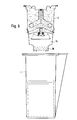
- the container of the embodiment of FIGS. 1 to 6 consists of a substantially cylindrical or conical outer container 1, which is provided in the lower part with an insulating wall reinforcement 2 and on one side with an extension 3 through which the drink can be consumed.
- a liquid storage container 4 is inserted, which has a bellows-like cover 5, which is biased so that it strives to move from the position of FIG. 1 to the position of FIG. 3, as long as it is not by the internal liquid pressure is prevented in the container 4.
- Electrical contacts 6 are provided on the container, which are electrically connected to heating elements 7, which can be a bare wire heating coil or an insulated sheathed heating resistor.
- the bottom 8 of the container is curved and has two stable positions, namely the inwardly curved position shown in FIGS. 1, 2, 5 and 6 and the outwardly curved position shown in FIGS. 3 and 4.
- the bottom 8 has a hole in the middle, which is surrounded by an annular or tubular projection 9.
- a mandrel 10 projects into this projection 9 and is fastened with a perforated plate 11 in the interior of the storage container 4.
- Lip seals 12 are arranged on the mandrel 10.
- a collapsible funnel 13 is arranged on the projection 9, the mode of operation of which will be described below.
- a cup-shaped element 14 is slipped onto the storage container 4, which element is held there by a snap-snap connection.
- the cup 14 has an opening at the bottom, which is partially closed by a sieve 15.
- the material 16 to be brewed is located above the sieve 15.
- Fig. 1 the cup is shown in the filled state.
- the cup In the position of FIG. 2, the cup is inserted into a holder 17 with a power supply, which has a movable contact 18 which is pressed against the contact 6 when the cup is pushed in, as is known from EP-A-0 382 001 is.
- the liquid in the storage container 4 is then heated by the heating elements 7, whereby the internal pressure in the container 4 gradually increases. If a sufficient temperature and thus a sufficient internal pressure in the container 4 has been reached, the bottom 8, as shown in FIG. 3, bulges outwards into its other stable position.
- the tubular projection 9 detaches from the mandrel 10 so that the liquid can now penetrate into the collecting space of the container 1 and thereby brews the material 16.
- the bellows-shaped cover 5 of the container 4 moves downwards in accordance with its prestress, so that the electrical connection between the contacts 18 and 6 is interrupted, so that the heating elements 7 are no longer supplied with current. So it does no harm if the container 1 is left in the holder 17 for a while.
- the cup 1 is then removed from the holder 17 in order to enjoy the drink.
- the container essentially consists of three parts, namely the cup 1, the storage container 4 and the cup-shaped part 14. For refilling, these three parts are separated from one another and cleaned.
- the container 4 is then turned upside down, as shown in Fig. 4, and the funnel 13 is folded upwards so that water can be filled from a tap 19 into the reservoir 4. If the storage container 4 is full, pressure is exerted on the funnel 13, as shown in FIG. 5. As a result, the funnel 13 is folded on the one hand so that it takes up less space.
- the bottom 8 is pressed down so that the closure consisting of the annular projection 9 and the mandrel 10 is closed again. The bottom 8 reaches its second, arched, stable position.
- cup-shaped element 14 is then replaced, into which the tablet-shaped material 16 to be brewed has been inserted.
- the assembly so assembled is then inserted into the outer cup 1 as shown in FIG. 6. Then you have the position of FIG. 1 again.
- FIGS. 7 to 13 have a similar mode of operation and differ essentially only in the design of the base 8 or the closure.
- the bottom has reinforcement fields 20. It also has a central opening with a tubular projection 9, which is closed with a film 21. Below the base 8, a mandrel 23 with pointed cutting edges is provided on a sieve-shaped base 22, a cross-shaped construction or the like. If the bottom moves downward, as shown in FIG. 9, the fixed mandrel 23 destroys the film 21, so that the liquid can pass down through the material 16 to be brewed into the collecting space.
- the bottom 8 is attached to the edge of the container in a manner similar to how a jam jar is closed. It is therefore only necessary to replace the base 8 with the film 21 after use, the remaining parts can be reused.
- two films 21 are provided, which form a film bag or which close a cylinder 24 on both sides, which is arranged at the opening of the bottom 8. If the base 8 moves into the downwardly curved position, both foils 21 are destroyed by the mandrel 23, so that the previously hermetically sealed brewing material can be carried into the collecting space by the hot liquid.
- Fig. 11 the upper part of the container of another embodiment is shown, which is inserted into a holder.
- the holder has a holder base 38 with a rocker support which has a rocker bearing 36 in which a switch rocker 45 is arranged.
- the holder is covered with a holder cover 40.
- the contacts via which the container is supplied with current are designed as spring plates 18 which make contact with the contact surfaces 6 of the container.
- the container is inserted into flange rails 39 of the holder, which hold the container on a container clamping ring 41.
- the membrane-like cover 5 can assume the three positions labeled A, B and C.
- A denotes the lid level after the water filling quantity has been heated
- B denotes the lid level in the pretensioned middle position
- C denotes the lid level in the relaxed manufacturing form.
- the lid base 32 designates the lifting center. With 33 heating coil connections are designated, which are arranged in hose sockets 34.
- the wall of the outer cup is designated 1, the wall of the inner cup 14 and the filling space for water 44.
- the valve of FIG. 12 has a piston valve 52 with a threaded pin and four quarter-circle inlet and outlet passages 55.
- the lower part of the piston valve thus has the cross-sectional shape of a cross.
- the piston valve 52 has a rolling slide ring 51 which can bear against the valve cylinder 56 in a sealing manner.
- a cross-shaped holding crossbar with a threaded connection base for the piston valve is designated. This lies against the wall of the inner cup 14.
- the valve cylinder 56 has vertical stabilizing plates attached and an external thread onto which a lock nut 57 with a flange surface is screwed. Between the valve cylinder 56 and lock nut 57, the flexible membrane base 8 is clamped, which is shown in the figure in three different positions, which are designated by 60, 61 and 62. In the illustration on the left, the diaphragm bottom 60 occupies the lowest position in which liquid can flow through the valve. In the right part of FIG. 12, the membrane base has the position labeled 61, in which sealing is still taking place, whereas in the illustration 62, complete sealing would take place. This is the state as it is in the filled container with the container not yet heated.
- the flexible cap which can be capped is designated by 13, while 59 denotes a base clamping ring with which the base 8 or 60, 61, 62 is clamped.
- the three valve cylinder positions are shown at 63, 64 and 65, the working stroke resulting from the distance between the positions 63 and 65.
- 66 is the ground lift.
- With 67 are a circulating flow sector, with 68 lower openings of the inlet and outlet passages are designated.
- the container parts 1, 4 and 14 can consist of plastic, metal or glass.
- the outer surface of the cup can be corrugated or serrated so as to reduce the contact area with the human hand and thus the heat transfer. In the embodiments with valve mandrels, this can be fixed, but also resilient. The remaining surfaces can also be smooth or wavy or serrated.
- the various bases can be ring-shaped or radially corrugated or serrated. If a soup is to be prepared, cup-shaped element 14 can of course be used to be dispensed with. The material 16 to be brewed is then arranged directly in the collecting space.
- the various parts can be connected to one another in a sealing manner by screw closures, as is known from canned jars. This makes it easier to refill or refill in foodstuffs, so that the containers can always be reused.
Abstract
Description
Die Erfindung betrifft einen in ein Stromversorgungsteil einsetzbaren Behälter zum Zubereiten heißer Getränke mit einem Flüssigkeitsvorratsbehälter, einem darin angeordneten elektrischen Heizelement und einem Sammelbehälter für das zubereitete Getränk, wobei der Flüssigkeitsvorratsbehälter einen Verschluß aufweist, der im Boden des Flüssigkeitsvorratsbehälters angeordnet ist und sich bei einem vorgegebenen Behälterinnendruck aufgrund Auswölbens des Bodens nach außen nicht selbsttätig umkehrbar öffnet, der mit Kontakten für die Zuleitung von elektrischem Strom versehen ist, die über eine elektrische Leitung mit dem Heizelement verbunden sind, und der in den Sammelbehälter so einsetzbar oder eingesetzt ist, daß sich in der Betriebsstellung der Sammelraum im wesentlichen unterhalb des Vorratsbehälters befindet, und wobei die Stromzufuhr zum Heizelement so ausgebildet ist, daß sie beim Öffnen des Verschlusses unterbrochen wird.The invention relates to a container for the preparation of hot drinks that can be inserted into a power supply part, with a liquid storage container, an electrical heating element arranged therein and a collecting container for the prepared drink, the liquid storage container having a closure which is arranged in the bottom of the liquid storage container and is at a predetermined internal container pressure due to bulging of the bottom to the outside does not automatically open reversibly, which is provided with contacts for the supply of electrical current, which are connected via an electrical line to the heating element, and which can be inserted or inserted into the collecting container in such a way that it is in the operating position the collecting space is located essentially below the storage container, and the power supply to the heating element is designed such that it is interrupted when the closure is opened.
Bekannte Behälter dieser Art (EP-A-0 382 001) können in einen Stromversorgungsteil eingeführt werden. Es wird dann eine Flüssigkeit, normalerweise Wasser, in dem Behälter erwärmt. Durch die Erwärmung steigt der Behälterinnendruck an, so daß sich der Boden des Flüssigkeitsvorratsbehälters nach außen wölbt und ein sich im Boden angeordneter Verschluß öffnet, so daß die heiße Flüssigkeit mit dem Brühmittel oder aufzubrühenden Material in Berührung kommt. Das so aufbereitete heiße Getränk sammelt sich dann im Sammelraum unterhalb des Flüssigkeitsvorratsbehältersund kann durch eine seitliche Öffnung getrunken werden oder (im Falle einer Suppe) mit einem Löffel gegessen werden, nachdem der Behälter aus dem Stromversorgungsteil entnommen und der Flüssigkeitsvorratsbehälter vom Sammelbehälter getrennt ist.Known containers of this type (EP-A-0 382 001) can be inserted into a power supply part. A liquid, usually water, is then heated in the container. The heating increases the internal pressure of the container, so that the bottom of the liquid reservoir bulges outwards and a closure arranged in the bottom opens, so that the hot liquid comes into contact with the brewing agent or material to be brewed. The hot beverage prepared in this way then collects in the collecting space below the liquid storage container and can be drunk through a side opening or (in the case of soup) eaten with a spoon after the container has been removed from the power supply part and the liquid storage container has been separated from the collecting container.
Bei der vorbekannten Ausführungsform weist der Verschluß einen feststehenden Dorn auf, der von einer mit einer Dichtung versehenen Öffnung des Bodens umschlossen wird. Eine solche Dichtung vermag aber insbesondere bei längerer Lagerung nicht zufriedenstellend zu arbeiten.In the known embodiment, the closure has a fixed mandrel which is enclosed by an opening in the base provided with a seal. However, such a seal is unable to work satisfactorily, particularly when stored for a long time.
Die Aufgabe der Erfindung besteht daher in der Schaffung eines Behälters, der im Bereich des Verschlusses besser abgedichtet ist.The object of the invention is therefore to create a container which is better sealed in the area of the closure.
Die erfindungsgemäße Lösung besteht darin, daß der Verschluß von einem eine Öffnung des Bodens umgebenden ringförmigen Vorsprung und einem im Inneren des Flüssigkeitsvorratsbehälters befestigten Dorn gebildet ist, und daß am Vorsprung und/oder Dorn Dichtungen angeordnet sind.The solution according to the invention is that the closure is formed by an annular projection surrounding an opening in the bottom and a mandrel fastened in the interior of the liquid storage container, and that seals are arranged on the projection and / or mandrel.
Man hat also nicht mehr eine mehr oder weniger linienförmige Dichtfläche zwischen Boden und Dorn, sondern einen größeren Bereich zwischen ringförmigem Vorsprung und Dorn, zwischen denen geeignete Dichtungen, insbesondere Lippendichtungen oder Rollringdichtungen angeordnet sind.So there is no longer a more or less linear sealing surface between the bottom and the mandrel, but a larger area between the annular projection and the mandrel, between which suitable seals, in particular lip seals or rolling ring seals, are arranged.
Ein weiterer Vorteil, daß der Dorn im Flüssigkeitsvorratsbehälter und nicht wie bei der vorbekannten Ausführungsform außerhalb desselben angeordnet ist, besteht darin, daß das aufzubrühende Material nicht mehr ringförmig um den Dorn angeordnet werden muß, sondern Zylinderform ähnlich einer Tablette haben kann. Ein weiterer Vorteil ist die geringere Zahl von Einzelteilen beim Zusammensetzen des Behälters, was es ermöglicht, daß diese Behälter wiederverwendbar ausgebildet werden können und dabei vom Verbraucher nach entsprechender Reinigung selbst wieder für zukünftige Verwendung befüllt werden können.Another advantage that the mandrel is arranged in the liquid storage container and not outside of it as in the previously known embodiment is that the material to be brewed no longer has to be arranged in a ring around the mandrel, but can have a cylindrical shape similar to a tablet. Another advantage is the smaller number of individual parts when assembling the container, which makes it possible for these containers to be designed to be reusable and, after appropriate cleaning, to be filled by the consumer himself for future use.
Vorteilhafterweise ist unten auf dem Flüssigkeitsvorratsbehälter ein becherförmiges Element mit dem aufzubrühenden Material aufgesetzt, das lösbar aufgesetzt sein sollte, wenn der Behälter vom Verbraucher selbst befüllt werden soll. Unten am ringförmigen Vorsprung kann ein Trichter angeordnet sein, der sich nach unten erweitert, so daß der Flüssigkeitsvorratsbehälter einfacher mit Flüssigkeit gefüllt werden kann, nachdem er auf den Kopf gestellt worden ist. "unten" bedeutet dabei immer die Seite, die sich in der Gebrauchsstellung unten befindet.Advantageously, a cup-shaped element with the material to be brewed is placed on the bottom of the liquid storage container, which should be releasably placed when the container is to be filled by the consumer himself. At the bottom of the annular projection a funnel can be arranged which widens downwards so that the liquid reservoir can be filled with liquid more easily after it has been turned upside down. "Below" always means the side that is in the use position below.
Der Trichter kann zusammenfaltbar sein, wie man es z.B. von Gegenlichtblenden von Fotoapparaten kennt, so daß er weniger Platz einnimmt, nachdem er seine Aufgabe erfüllt hat, daß der Flüssigkeitsvorratsbehälter leichter mit Flüssigkeit gefüllt werden kann.The funnel can be collapsible, e.g. known from lens hoods of cameras, so that it takes up less space after it has done its job of making it easier to fill the liquid reservoir with liquid.
Eine weitere erfindungsgemäße Lösung zeichnet sich dadurch aus, daß der Verschluß eine mechanisch aufbrechbare Versiegelung aufweist. Diese Lösung wird immer dann vorgezogen werden, wenn auch die aufwendige Dichtung, wie sie oben beschrieben ist, nicht ausreicht.Another solution according to the invention is characterized in that the closure has a mechanically breakable seal. This solution will always be preferred if the complex seal as described above is not sufficient.
Dabei kann der Verschluß eine die Öffnung des Bodens verschließende Folie sein, die beim Aufwölben des Bodens durch einen außerhalb des Flüssigkeitsbehälters angeordneten Dorn zerstört wird. Auf diese Weise ist die Flüssigkeit im Flüssigkeitsbehälter vor dem Gebrauch hermetisch abgeschlossen und bleibt dort jahrelang frisch und sauber.The closure can be a film which closes the opening of the base and is destroyed when the base is arched by a mandrel arranged outside the liquid container. In this way, the liquid in the liquid container is hermetically sealed before use and stays fresh and clean there for years.
Statt der einen Folie könnte man hier auch einen Folienbeutel vorsehen, der die Öffnung fest verschließt, wobei dann die Folien auf beiden Seiten des Folienbeutels durch den Dorn zerstört würden. Auf diese Weise kann auch das aufzubrühende Material sehr lange hermetisch abgeschlossen bleiben.Instead of one film, one could also provide a film bag that tightly closes the opening, in which case the films on both sides of the film bag would be destroyed by the mandrel. In this way, the material to be brewed can remain hermetically sealed for a very long time.
Die Erfindung wird im folgenden anhand von vorteilhaften Ausführungsformen unter Bezugnahme auf die beigefügten Zeichnungen beschrieben.The invention is described below with reference to advantageous embodiments with reference to the accompanying drawings.
Es zeigen:
- Fig. 1 bis 3 eine erste Ausführungsform des Behälters in verschiedenen Arbeitsstellungen bei der Herstellung des heißen Getränkes;
- Fig. 4 bis 6 den Behälter der
Figuren 1 bis 3 bei verschiedenen Arbeitsstellungen bei der Befüllung oder Wiederbefüllung; - Fig. 7 in ähnlicher Ansicht wie in den Fig. 1 bis 6 den Boden des Flüsslgkeitsvorratsbehälters mit einer anderen Art des Verschlusses;
- Fig. 8 den Boden des Flüssigkeitsvorratsbehälters der Ausführungsform der Fig. 7 in Draufsicht;
- Fig. 9 den Boden des Behälters der
- Fig. 7 in einer Stellung, in der die Flüssigkeit aus dem Flüssigkeitsbehälter heraustritt;
- Fig. 10 eine andere Ausführungsform ähnlich derjenigen der Fig. 7;
- Fig. 11 im Querschnitt den oberen Teil des Behälters in ähnlicher Ausführungsform wie bei den Fig. 1 bis 3, der in einer Halterung eingeschoben ist; und
- Fig. 12 in vergrößerter Darstellung den Ventilbereich eines Behälters in einer ähnlichen Ausführungsform wie derjenigen der Fig. 1 bis 3.
- Figures 1 to 3 a first embodiment of the container in different working positions in the manufacture of the hot beverage;
- 4 to 6 the container of FIGS. 1 to 3 in different working positions during filling or refilling;
- Fig. 7 in a similar view as in Figures 1 to 6, the bottom of the liquid storage container with a different type of closure.
- 8 shows the bottom of the liquid storage container of the embodiment of FIG. 7 in a top view;
- Fig. 9 shows the bottom of the container
- 7 in a position in which the liquid emerges from the liquid container;
- Fig. 10 shows another embodiment similar to that of Fig. 7;
- Fig. 11 in cross section the upper part of the container in a similar embodiment as in Figures 1 to 3, which is inserted in a holder. and
- 12 shows an enlarged view of the valve region of a container in a similar embodiment to that of FIGS. 1 to 3.
Der Behälter der Ausführungsform der Fig. 1 bis 6 besteht aus einem im wesentlichen zylinderförmigen oder konusförmigen Außenbehälter 1, der im unteren Teil mit einer isolierenden Wandverstärkung 2 und an einer Seite mit einer Erweiterung 3 versehen ist, durch die das Getränk konsumiert werden kann.The container of the embodiment of FIGS. 1 to 6 consists of a substantially cylindrical or conical
In den Behälter 1 ist ein Flüssigkeitsvorratsbehälter 4 eingesetzt, der einen balgartigen Deckel 5 aufweist, der so vorgespannt ist, daß er von der Stellung der Fig. 1 in die Stellung der Fig. 3 sich zu bewegen bestrebt ist, solange er nicht durch den Flüssigkeitsinnendruck im Behälter 4 daran gehindert wird. Am Behälter sind elektrische Kontakte 6 vorgesehen, die mit Heizelementen 7 elektrisch verbunden sind, die eine Blankdrahtheizwendel oder ein isolierter ummantelter Heizwiderstand sein können.In the
Der Boden 8 des Behälters ist gewölbt und hat zwei stabile Stellungen, nämlich die in den Fig. 1, 2, 5 und 6 gezeigte nach innen gewölbte Stellung und die in den Fig. 3 und 4 gezeigte nach außen gewölbte Stellung. Der Boden 8 weist in der Mitte ein Loch auf, das von einem ring- oder rohrförmigen Vorsprung 9 umgeben ist. In diesen Vorsprung 9 ragt ein Dorn 10 hinein, der mit einer gelochten Platte 11 im Inneren des Vorratsbehälters 4 befestigt ist. Am Dorn 10 sind Lippendichtungen 12 angeordnet. Weiter ist am Vorsprung 9 noch ein zusammenklappbarer Trichter 13 angeordnet, dessen Wirkungsweise weiter unten beschrieben werden wird.The
Auf den Vorrratsbehälter 4 ist ein becherförmiges Element 14 aufgestülpt, das dort von einer Schnapp-Rast-Verbindung festgehalten wird. Der Becher 14 weist unten eine Öffnung auf, die von einem Sieb 15 teilweise verschlossen ist. Oberhalb des Siebes 15 befindet sich das aufzubrühende Material 16.A cup-
In Fig. 1 ist der Becher im befüllten Zustand gezeigt. In der Stellung der Fig. 2 ist der Becher in eine Halterung 17 mit einer Stromversorgung eingeschoben, die einen beweglichen Kontakt 18 aufweist, der beim Einschieben des Bechers gegen den Kontakt 6 gedrückt wird, wie dies aus der EP-A-0 382 001 bekannt ist. Die Flüssigkeit im Vorratsbehälter 4 wird dann durch die Heizelemente 7 erwärmt, wodurch allmählich der Innendruck im Behälter 4 ansteigt. Ist eine ausreichende Temperatur und damit ein ausreichender Innendruck im Behälter 4 erreicht, so wölbt sich der Boden 8, wie dies in Fig. 3 gezeigt ist, nach außen in seine andere stabile Stellung. Der rohrförmige Vorsprung 9 löst sich dabei vom Dorn 10, so daß nunmehr die Flüssigkeit in den Sammelraum des Behälters 1 dringen kann und dabei das Material 16 aufbrüht. Da der Innendruck im Vorratsbehälter 4 abgesunken ist, bewegt sich der balgförmige Deckel 5 des Behälters 4 entsprechend seiner Vorspannung nach unten, so daß die elektrische Verbindung zwischen den Kontakten 18 und 6 unterbrochen wird, so daß die Heizelemente 7 nicht mehr mit Strom versorgt werden. Es schadet also nicht, wenn der Behälter 1 noch für einige Zeit in der Halterung 17 belassen wird.In Fig. 1 the cup is shown in the filled state. In the position of FIG. 2, the cup is inserted into a
Um das Getränk zu genießen wird dann der Becher 1 aus der Halterung 17 herausgenommen.The
In der in den Fig. 1 bis 3 gezeigten Ausführungsform besteht der Behälter im wesentlichen aus drei Teilen, nämlich dem Becher 1, dem Vorratsbehälter 4 und dem becherförmigen Teil 14. Zum Wiederbefüllen werden diese drei Teile voneinander getrennt und gereinigt. Der Behälter 4 wird dann auf den Kopf gestellt, wie dies in Fig. 4 gezeigt ist, und es wird der Trichter 13 nach oben gefaltet, so daß Wasser aus einem Wasserhahn 19 in den Vorratsbehälter 4 gefüllt werden kann. Ist der Vorratsbehälter 4 voll, so wird Druck auf den Trichter 13 ausgeübt, wie dies in Fig. 5 gezeigt ist. Dadurch wird einerseits der Trichter 13 zusammengefaltet, so daß er weniger Raum beansprucht. Andererseits wird der Boden 8 nach unten gedrückt, so daß der aus ringförmigem Vorsprung 9 und Dorn 10 bestehende Verschluß wieder geschlossen wird. Der Boden 8 erreicht seine zweite, nach innen gewölbte, stabile Stellung.In the embodiment shown in FIGS. 1 to 3, the container essentially consists of three parts, namely the
Anschließend wird dann das becherförmige Element 14 wieder aufgesetzt, in das das tablettenförmige aufzubrühende Material 16 eingesetzt wurde. Die so zusammengesetzte Anordnung wird dann in den äußeren Becher 1 eingesetzt, wie dies in Fig. 6 gezeigt ist. Danach hat man dann wieder die Stellung der Fig. 1.Then the cup-shaped
Die Ausführungsformen der Fig. 7 bis 13 haben eine ähnliche Wirkungsweise und unterscheiden sich im wesentlichen nur durch die Ausbildung des Bodens 8 bzw. des Verschlusses.The embodiments of FIGS. 7 to 13 have a similar mode of operation and differ essentially only in the design of the
Bei der Ausführungsform der Fig. 7 bis 9 weist der Boden Verstärkungsfelder 20 auf. Er weist weiter eine mittige Öffnung mit einem rohrförmigen Vorsprung 9 auf, die mit einer Folie 21 verschlossen ist. Unterhalb des Bodens 8 ist an einem siebförmigen Boden 22, einer kreuzförmigen Konstruktion oder dergleichen ein Dorn 23 mit spitzen Schneiden vorgesehen. Bewegt sich der Boden nach unten, wie dies in Fig. 9 gezeigt ist, zerstört der feststehende Dorn 23 die Folie 21, so daß die Flüssigkeit durch das aufzubrühende Material 16 nach unten in den Sammelraum treten kann.In the embodiment of FIGS. 7 to 9, the bottom has reinforcement fields 20. It also has a central opening with a
Da die Behälter der Erfindung zweckmäßigerweise wiederverwendbar sein sollen, ist hier vorgesehen, daß der Boden 8 am Rande mit dem Behälter auf ähnliche Weise befestigt ist, wie ein Marmeladenglas verschlossen wird. Es braucht also nach Gebrauch nur der Boden 8 mit der Folie 21 ausgewechselt werden, die übrigen Teile können wiederverwendet werden.Since the containers of the invention should expediently be reusable, it is provided here that the
Bei der Ausführungsform der Fig. 10 sind statt einer Folie zwei Folien 21 vorgesehen, die einen Folienbeutel bilden oder die einen Zylinder 24 auf beiden Seiten verschließen, der an der Öffnung des Bodens 8 angeordnet ist. Bewegt sich der Boden 8 in die nach unten gewölbte Stellung, so werden beide Folien 21 durch den Dorn 23 zerstört, so daß das vorher hermetisch eingeschlossene Brühmaterial von der heißen Flüssigkeit in den Sammelraum mitgeführt werden kann.In the embodiment of FIG. 10, instead of one film, two
In Fig. 11 ist der obere Teil des Behälters einer anderen Ausführungsform gezeigt, der in eine Halterung eingeschoben ist. Die Halterung weist eine Halterbasis 38 mit einem Wippenträger auf, der ein Wippenlager 36 aufweist, in der eine Schalterwippe 45 angeordnet ist. Die Halterung ist mit einer Halterabdeckung 40 abgedeckt. Die Kontakte, über die der Behälter mit Strom versorgt wird, sind als Federbleche 18 ausgebildet, die mit den Kontaktflächen 6 des Behälters Kontakt herstellen. Der Behälter ist in Flanschschienen 39 der Halterung eingeschoben, die den Behälter an einem Behälterspannring 41 festhalten. Der membranartige Deckel 5 kann dabei die drei mit A, B und C bezeichneten Stellungen einnehmen. A bezeichnet dabei die Deckelebene nach dem Aufheizen der Wasserfüllmenge, B bezeichnet die Deckelebene in der vorgespannten Mittelstellung, und C bezeichnet die Deckelebene in der entspannten Fertigungsform. Die Deckelbasis 32 bezeichnet dabei das Hubzentrum. Mit 33 sind Heizwendelanschlüsse bezeichnet, die in Schlauchbuchsen 34 angeordnet sind. Die Wandung des Außenbechers ist mit 1, die Wandung des inneren Bechers mit 14 und der Füllraum für Wasser mit 44 bezeichnet.In Fig. 11 the upper part of the container of another embodiment is shown, which is inserted into a holder. The holder has a
Das Ventil der Fig. 12 weist ein Kolbenventil 52 mit einem Gewindezapfen und vier Viertelkreisein-und -auslaufpassagen 55 auf. Der untere Teil des Kolbenventils hat also die Querschnittsform eines Kreuzes. Das Kolbenventil 52 weist einen Roll-Gleitring 51 auf, der gegen den Ventilzylinder 56 dichtend anliegen kann. Mit 53 ist eine kreuzförmige Haltetraverse mit Gewindeanschlußbasis für das Kolbenventil bezeichnet. Diese liegt an der Wandung des Innenbechers 14 an.The valve of FIG. 12 has a
Der Ventilzylinder 56 weist aufgesetzte senkrechte Stabilisierungslamellen und ein Außengewinde auf, auf das eine Kontermutter 57 mit Flanschfläche aufgeschraubt ist. Zwischen Ventilzylinder 56 und Kontermutter 57 ist der flexible Membranboden 8 eingespannt, der in der Fig. in drei verschiedenen Stellungen dargestellt ist, die mit 60, 61 und 62 bezeichnet sind. In der linken Darstellung nimmt dabei der Membranboden 60 die unterste Stellung ein, in der Flüssigkeit durch das Ventil hindurchströmen kann. Im rechten Teil der Fig. 12 hat der Membranboden die mit 61 bezeichnete Stellung, in der gerade noch Abdichtung stattfindet, während bei der Darstellung 62 vollständige Abdichtung stattfinden würde. Dies ist der Zustand, wie er beim befüllten Behälter mit noch nicht erhitztem Behälterinhalt vorliegt.The
Mit 13 ist der flexible kappbare Trichter bezeichnet, während 59 einen Bodenspannring bezeichnet, mit dem der Boden 8 bzw. 60, 61, 62 eingespannt ist. Mit 63, 64 und 65 sind die drei Ventilzylinderstellungen dargestellt, wobei sich der Arbeitshub aus dem Abstand der Stellungen 63 und 65 ergibt. 66 ist der Bodenhub. Mit 67 sind noch ein umlaufender Durchflußsektor, mit 68 sind untere Öffnungen der Ein- und Auslaufpassagen bezeichnet.The flexible cap which can be capped is designated by 13, while 59 denotes a base clamping ring with which the
Die Behälterteile 1, 4 und 14 können aus Kunststoff, Metall oder Glas bestehen. Die Becheraußenfläche kann gewellt oder gezackt sein, um so die Berührungsfläche mit der menschlichen Hand und damit den Wärmeübergang zu verringern. Bei den Ausführungsformen mit Ventildornen kann dieser fest, aber auch federnd, angebracht sein. Auch die übrigen Flächen können glattförmig oder gewellt oder gezackt sein. Die verschiedenen Böden können dabei ringförmig oder radial gewellt bzw. gezackt sein. Falls eine Suppe bereitet werden soll, kann natürlich auf das becherförmige Element 14 verzichtet werden. Das aufzubrühende Material 16 wird dann direkt im Sammelraum angeordnet. Die verschiedenen Teile können wie gesagt durch Schraubverschlüsse miteinander dichtend verbunden sein, wie man sie von Konservengläsern kennt. Dadurch wird die eigene Wiederbefüllung bzw. das Wiederbefüllen in Lebensmittelbetrieben erleichtert, so daß die Behälter immer wiederverwendet werden können.The
Claims (10)
Applications Claiming Priority (2)
| Application Number | Priority Date | Filing Date | Title |
|---|---|---|---|
| DE9013838U | 1990-10-04 | ||
| DE9013838U DE9013838U1 (en) | 1990-10-04 | 1990-10-04 |
Publications (2)
| Publication Number | Publication Date |
|---|---|
| EP0479111A1 true EP0479111A1 (en) | 1992-04-08 |
| EP0479111B1 EP0479111B1 (en) | 1995-03-08 |
Family
ID=6858073
Family Applications (1)
| Application Number | Title | Priority Date | Filing Date |
|---|---|---|---|
| EP91116360A Expired - Lifetime EP0479111B1 (en) | 1990-10-04 | 1991-09-25 | Container for making hot drinks |
Country Status (9)
| Country | Link |
|---|---|
| US (1) | US5287796A (en) |
| EP (1) | EP0479111B1 (en) |
| JP (1) | JPH04364818A (en) |
| AT (1) | ATE119368T1 (en) |
| DE (2) | DE9013838U1 (en) |
| DK (1) | DK0479111T3 (en) |
| ES (1) | ES2071182T3 (en) |
| HK (1) | HK157995A (en) |
| RU (1) | RU1837834C (en) |
Cited By (2)
| Publication number | Priority date | Publication date | Assignee | Title |
|---|---|---|---|---|
| WO1996022719A1 (en) * | 1995-01-26 | 1996-08-01 | Eberhard Timm | Device for heating a drinkable liquid |
| EP1118298A1 (en) * | 2000-01-20 | 2001-07-25 | Eberhard Timm | Device for preparing hot beverages |
Families Citing this family (13)
| Publication number | Priority date | Publication date | Assignee | Title |
|---|---|---|---|---|
| US5799566A (en) * | 1997-02-07 | 1998-09-01 | Massachusetts Institute Of Technology | Self-propelled moving-filter beverage maker |
| DE29801337U1 (en) * | 1998-01-28 | 1999-05-27 | Muench Gmbh | Device for heating drinking water |
| DE29802766U1 (en) * | 1998-02-18 | 1999-07-22 | Muench Gmbh | Device for heating drinking water |
| NL1009143C2 (en) * | 1998-05-13 | 1999-11-16 | Mr H H Q Abeln B V | Transportable coffee percolator for making coffee at any time and place |
| FR2806896B1 (en) * | 2000-03-28 | 2002-11-08 | Michel Vannoye | COMPACT HOT WATER DISPENSER FOR HOT BEVERAGE |
| PT1604915T (en) * | 2002-01-16 | 2016-11-02 | Nestle Sa | Closed capsule with opening means |
| ATE339141T1 (en) * | 2002-10-03 | 2006-10-15 | Tuttoespresso Spa | DISPENSING DEVICE FOR PREPARING DRINKS FROM DISSOLVABLE PRODUCTS |
| EP1468635B1 (en) * | 2003-04-17 | 2005-06-22 | Eberhard Timm | Device for preparing hot beverages |
| CA2829795C (en) * | 2004-03-26 | 2014-08-05 | Illycaffe' S.P.A. | Integrated cartridge for extracting a beverage from a particulate substance |
| ES2243127B1 (en) * | 2004-04-02 | 2007-01-01 | Isluce, S.L. | COFFEE MACHINE FOR OBTAINING INFUSIONS FROM SOLID PRODUCTS CONTAINED IN A GLASS. |
| RU2463943C2 (en) * | 2007-05-31 | 2012-10-20 | Конинклейке Филипс Электроникс Н.В. | Device for making beverages, having container for water and element for sizing outlet of container for water |
| US20090007791A1 (en) * | 2007-07-02 | 2009-01-08 | Hsing-Hui Chen | Cup Having Floatable Strainer |
| USD766656S1 (en) | 2015-03-05 | 2016-09-20 | 8479950 Canada Inc. | Filter |
Citations (5)
| Publication number | Priority date | Publication date | Assignee | Title |
|---|---|---|---|---|
| DE1404799A1 (en) * | 1959-02-06 | 1968-12-12 | Sealpack Corp | Method and device for making white coffee |
| DE2212283A1 (en) * | 1972-03-14 | 1973-09-27 | O & N Electric As | INLET OR OUTLET VALVE, PRESENTLY FOR COFFEE MACHINES |
| US3804134A (en) * | 1972-08-17 | 1974-04-16 | Continental Oil Co | Collapsible funnel for dispensing liquids from puncturable containers |
| FR2579880A1 (en) * | 1985-04-03 | 1986-10-10 | Daibilian Stephan | Device for preparing hot and cold drinks |
| EP0382001B1 (en) * | 1989-02-09 | 1993-04-07 | Eberhard Timm | Apparatus for making hot drinks |
Family Cites Families (5)
| Publication number | Priority date | Publication date | Assignee | Title |
|---|---|---|---|---|
| US2292853A (en) * | 1940-07-05 | 1942-08-11 | Albert C Wilcox | Automatic electric drip coffee maker |
| US2498386A (en) * | 1945-11-19 | 1950-02-21 | Victor R Alexander | Coffee-making apparatus |
| US2856843A (en) * | 1957-08-02 | 1958-10-21 | Gen Electric | Liquid heating and metering construction |
| US3423209A (en) * | 1965-11-23 | 1969-01-21 | Robert L Weber | Brewing selectable variable quantities of coffee |
| US4997015A (en) * | 1988-10-17 | 1991-03-05 | Black & Decker, Inc. | Brew through lid for coffee maker |
-
1990
- 1990-10-04 DE DE9013838U patent/DE9013838U1/de not_active Expired - Lifetime
-
1991
- 1991-09-24 US US07/764,830 patent/US5287796A/en not_active Expired - Fee Related
- 1991-09-25 AT AT91116360T patent/ATE119368T1/en not_active IP Right Cessation
- 1991-09-25 EP EP91116360A patent/EP0479111B1/en not_active Expired - Lifetime
- 1991-09-25 DK DK91116360.8T patent/DK0479111T3/en active
- 1991-09-25 ES ES91116360T patent/ES2071182T3/en not_active Expired - Lifetime
- 1991-09-25 DE DE59104862T patent/DE59104862D1/en not_active Expired - Fee Related
- 1991-10-03 RU SU915001997A patent/RU1837834C/en active
- 1991-10-04 JP JP3257522A patent/JPH04364818A/en active Pending
-
1995
- 1995-10-05 HK HK157995A patent/HK157995A/en not_active IP Right Cessation
Patent Citations (5)
| Publication number | Priority date | Publication date | Assignee | Title |
|---|---|---|---|---|
| DE1404799A1 (en) * | 1959-02-06 | 1968-12-12 | Sealpack Corp | Method and device for making white coffee |
| DE2212283A1 (en) * | 1972-03-14 | 1973-09-27 | O & N Electric As | INLET OR OUTLET VALVE, PRESENTLY FOR COFFEE MACHINES |
| US3804134A (en) * | 1972-08-17 | 1974-04-16 | Continental Oil Co | Collapsible funnel for dispensing liquids from puncturable containers |
| FR2579880A1 (en) * | 1985-04-03 | 1986-10-10 | Daibilian Stephan | Device for preparing hot and cold drinks |
| EP0382001B1 (en) * | 1989-02-09 | 1993-04-07 | Eberhard Timm | Apparatus for making hot drinks |
Cited By (2)
| Publication number | Priority date | Publication date | Assignee | Title |
|---|---|---|---|---|
| WO1996022719A1 (en) * | 1995-01-26 | 1996-08-01 | Eberhard Timm | Device for heating a drinkable liquid |
| EP1118298A1 (en) * | 2000-01-20 | 2001-07-25 | Eberhard Timm | Device for preparing hot beverages |
Also Published As
| Publication number | Publication date |
|---|---|
| RU1837834C (en) | 1993-08-30 |
| EP0479111B1 (en) | 1995-03-08 |
| JPH04364818A (en) | 1992-12-17 |
| DK0479111T3 (en) | 1995-07-24 |
| HK157995A (en) | 1995-10-13 |
| DE59104862D1 (en) | 1995-04-13 |
| ATE119368T1 (en) | 1995-03-15 |
| US5287796A (en) | 1994-02-22 |
| DE9013838U1 (en) | 1992-02-06 |
| ES2071182T3 (en) | 1995-06-16 |
Similar Documents
| Publication | Publication Date | Title |
|---|---|---|
| EP0479111B1 (en) | Container for making hot drinks | |
| DE69916034T2 (en) | REMOVAL CLOSURE FOR A BEVERAGE CONTAINER | |
| EP0019794B1 (en) | Water purification apparatus | |
| DE2528379A1 (en) | BEVERAGE MAKER | |
| DE10129416A1 (en) | Containers with separate receiving rooms | |
| DE2934711A1 (en) | RELOCKABLE LIQUID CONTAINER | |
| EP0382001B1 (en) | Apparatus for making hot drinks | |
| DE2742610C2 (en) | oilcontainer | |
| DE1057289B (en) | Atomizer for substances kept under pressure in a container made of glass, especially liquids | |
| EP0011278B1 (en) | Device to repeatedly open and close an aperture in the lid of a container | |
| EP1468635B1 (en) | Device for preparing hot beverages | |
| DE3347629A1 (en) | CONTAINER FOR CREAM-LIKE FLUIDS | |
| DE2350825A1 (en) | DEVICE FOR STORAGE AND DISPENSING OF LIQUID | |
| EP0802754B1 (en) | Device for heating a drinkable liquid | |
| EP1118298B1 (en) | Device for preparing hot beverages | |
| WO1983003239A1 (en) | Cap intended to be placed on the central outlet opening of a liquid container | |
| DE2940919A1 (en) | AIR-TIGHT SEALED, IN PARTICULAR PHARMACEUTICAL CONTAINER | |
| DE102016009483B4 (en) | Container closure system | |
| DE3104070C2 (en) | Swiveling hinged lid for a bottle-like vessel | |
| DE3347713C2 (en) | Closure arrangement with rotary knob and stopper for a vessel | |
| DE1961542A1 (en) | Fluid applicator | |
| EP0714835B1 (en) | Device for mixing two components | |
| DE3236552A1 (en) | Pump metering closure | |
| EP0165494A1 (en) | Kitchen appliance | |
| DE761216C (en) | Container closure, in particular for fuel containers in motor vehicles |
Legal Events
| Date | Code | Title | Description |
|---|---|---|---|
| PUAI | Public reference made under article 153(3) epc to a published international application that has entered the european phase |
Free format text: ORIGINAL CODE: 0009012 |
|
| AK | Designated contracting states |
Kind code of ref document: A1 Designated state(s): AT BE CH DE DK ES FR GB GR IT LI LU NL SE |
|
| 17P | Request for examination filed |
Effective date: 19920616 |
|
| 17Q | First examination report despatched |
Effective date: 19940128 |
|
| GRAA | (expected) grant |
Free format text: ORIGINAL CODE: 0009210 |
|
| AK | Designated contracting states |
Kind code of ref document: B1 Designated state(s): AT BE CH DE DK ES FR GB GR IT LI LU NL SE |
|
| PG25 | Lapsed in a contracting state [announced via postgrant information from national office to epo] |
Ref country code: GR Free format text: LAPSE BECAUSE OF FAILURE TO SUBMIT A TRANSLATION OF THE DESCRIPTION OR TO PAY THE FEE WITHIN THE PRESCRIBED TIME-LIMIT Effective date: 19950308 |
|
| REF | Corresponds to: |
Ref document number: 119368 Country of ref document: AT Date of ref document: 19950315 Kind code of ref document: T |
|
| REF | Corresponds to: |
Ref document number: 59104862 Country of ref document: DE Date of ref document: 19950413 |
|
| ITF | It: translation for a ep patent filed |
Owner name: UFFICIO TECNICO ING. A. MANNUCCI |
|
| ET | Fr: translation filed | ||
| REG | Reference to a national code |
Ref country code: ES Ref legal event code: FG2A Ref document number: 2071182 Country of ref document: ES Kind code of ref document: T3 |
|
| GBT | Gb: translation of ep patent filed (gb section 77(6)(a)/1977) |
Effective date: 19950605 |
|
| REG | Reference to a national code |
Ref country code: DK Ref legal event code: T3 |
|
| PLBE | No opposition filed within time limit |
Free format text: ORIGINAL CODE: 0009261 |
|
| STAA | Information on the status of an ep patent application or granted ep patent |
Free format text: STATUS: NO OPPOSITION FILED WITHIN TIME LIMIT |
|
| 26N | No opposition filed | ||
| PGFP | Annual fee paid to national office [announced via postgrant information from national office to epo] |
Ref country code: GB Payment date: 19980720 Year of fee payment: 8 Ref country code: FR Payment date: 19980720 Year of fee payment: 8 |
|
| PGFP | Annual fee paid to national office [announced via postgrant information from national office to epo] |
Ref country code: SE Payment date: 19980922 Year of fee payment: 8 Ref country code: BE Payment date: 19980922 Year of fee payment: 8 Ref country code: AT Payment date: 19980922 Year of fee payment: 8 |
|
| PGFP | Annual fee paid to national office [announced via postgrant information from national office to epo] |
Ref country code: LU Payment date: 19980923 Year of fee payment: 8 Ref country code: DK Payment date: 19980923 Year of fee payment: 8 |
|
| PGFP | Annual fee paid to national office [announced via postgrant information from national office to epo] |
Ref country code: ES Payment date: 19980928 Year of fee payment: 8 |
|
| PGFP | Annual fee paid to national office [announced via postgrant information from national office to epo] |
Ref country code: CH Payment date: 19980929 Year of fee payment: 8 |
|
| PGFP | Annual fee paid to national office [announced via postgrant information from national office to epo] |
Ref country code: NL Payment date: 19980930 Year of fee payment: 8 |
|
| PGFP | Annual fee paid to national office [announced via postgrant information from national office to epo] |
Ref country code: DE Payment date: 19981123 Year of fee payment: 8 |
|
| PG25 | Lapsed in a contracting state [announced via postgrant information from national office to epo] |
Ref country code: LU Free format text: LAPSE BECAUSE OF NON-PAYMENT OF DUE FEES Effective date: 19990925 Ref country code: GB Free format text: LAPSE BECAUSE OF NON-PAYMENT OF DUE FEES Effective date: 19990925 Ref country code: DK Free format text: LAPSE BECAUSE OF NON-PAYMENT OF DUE FEES Effective date: 19990925 Ref country code: AT Free format text: LAPSE BECAUSE OF NON-PAYMENT OF DUE FEES Effective date: 19990925 |
|
| PG25 | Lapsed in a contracting state [announced via postgrant information from national office to epo] |
Ref country code: ES Free format text: LAPSE BECAUSE OF NON-PAYMENT OF DUE FEES Effective date: 19990926 |
|
| PG25 | Lapsed in a contracting state [announced via postgrant information from national office to epo] |
Ref country code: SE Free format text: THE PATENT HAS BEEN ANNULLED BY A DECISION OF A NATIONAL AUTHORITY Effective date: 19990929 |
|
| PG25 | Lapsed in a contracting state [announced via postgrant information from national office to epo] |
Ref country code: LI Free format text: LAPSE BECAUSE OF NON-PAYMENT OF DUE FEES Effective date: 19990930 Ref country code: CH Free format text: LAPSE BECAUSE OF NON-PAYMENT OF DUE FEES Effective date: 19990930 Ref country code: BE Free format text: LAPSE BECAUSE OF NON-PAYMENT OF DUE FEES Effective date: 19990930 |
|
| BERE | Be: lapsed |
Owner name: TIMM EBERHARD Effective date: 19990930 |
|
| PG25 | Lapsed in a contracting state [announced via postgrant information from national office to epo] |
Ref country code: NL Free format text: LAPSE BECAUSE OF NON-PAYMENT OF DUE FEES Effective date: 20000401 |
|
| EUG | Se: european patent has lapsed |
Ref document number: 91116360.8 |
|
| REG | Reference to a national code |
Ref country code: CH Ref legal event code: PL |
|
| GBPC | Gb: european patent ceased through non-payment of renewal fee |
Effective date: 19990925 |
|
| PG25 | Lapsed in a contracting state [announced via postgrant information from national office to epo] |
Ref country code: FR Free format text: LAPSE BECAUSE OF NON-PAYMENT OF DUE FEES Effective date: 20000531 |
|
| NLV4 | Nl: lapsed or anulled due to non-payment of the annual fee |
Effective date: 20000401 |
|
| PG25 | Lapsed in a contracting state [announced via postgrant information from national office to epo] |
Ref country code: DE Free format text: LAPSE BECAUSE OF NON-PAYMENT OF DUE FEES Effective date: 20000701 |
|
| REG | Reference to a national code |
Ref country code: DK Ref legal event code: EBP |
|
| REG | Reference to a national code |
Ref country code: FR Ref legal event code: ST |
|
| REG | Reference to a national code |
Ref country code: ES Ref legal event code: FD2A Effective date: 20001013 |
|
| PG25 | Lapsed in a contracting state [announced via postgrant information from national office to epo] |
Ref country code: IT Free format text: LAPSE BECAUSE OF NON-PAYMENT OF DUE FEES;WARNING: LAPSES OF ITALIAN PATENTS WITH EFFECTIVE DATE BEFORE 2007 MAY HAVE OCCURRED AT ANY TIME BEFORE 2007. THE CORRECT EFFECTIVE DATE MAY BE DIFFERENT FROM THE ONE RECORDED. Effective date: 20050925 |