EP0477687B1 - Method and device for the protection of roofs, terraces and the like from the sun - Google Patents
Method and device for the protection of roofs, terraces and the like from the sun Download PDFInfo
- Publication number
- EP0477687B1 EP0477687B1 EP19910115466 EP91115466A EP0477687B1 EP 0477687 B1 EP0477687 B1 EP 0477687B1 EP 19910115466 EP19910115466 EP 19910115466 EP 91115466 A EP91115466 A EP 91115466A EP 0477687 B1 EP0477687 B1 EP 0477687B1
- Authority
- EP
- European Patent Office
- Prior art keywords
- sun
- hollow
- cylinders
- cylinder
- sectional area
- Prior art date
- Legal status (The legal status is an assumption and is not a legal conclusion. Google has not performed a legal analysis and makes no representation as to the accuracy of the status listed.)
- Expired - Lifetime
Links
Images

Classifications
-
- E—FIXED CONSTRUCTIONS
- E06—DOORS, WINDOWS, SHUTTERS, OR ROLLER BLINDS IN GENERAL; LADDERS
- E06B—FIXED OR MOVABLE CLOSURES FOR OPENINGS IN BUILDINGS, VEHICLES, FENCES OR LIKE ENCLOSURES IN GENERAL, e.g. DOORS, WINDOWS, BLINDS, GATES
- E06B9/00—Screening or protective devices for wall or similar openings, with or without operating or securing mechanisms; Closures of similar construction
- E06B9/24—Screens or other constructions affording protection against light, especially against sunshine; Similar screens for privacy or appearance; Slat blinds
-
- E—FIXED CONSTRUCTIONS
- E04—BUILDING
- E04C—STRUCTURAL ELEMENTS; BUILDING MATERIALS
- E04C2/00—Building elements of relatively thin form for the construction of parts of buildings, e.g. sheet materials, slabs, or panels
- E04C2/30—Building elements of relatively thin form for the construction of parts of buildings, e.g. sheet materials, slabs, or panels characterised by the shape or structure
- E04C2/42—Gratings; Grid-like panels
-
- E—FIXED CONSTRUCTIONS
- E04—BUILDING
- E04C—STRUCTURAL ELEMENTS; BUILDING MATERIALS
- E04C2/00—Building elements of relatively thin form for the construction of parts of buildings, e.g. sheet materials, slabs, or panels
- E04C2/54—Slab-like translucent elements
-
- E—FIXED CONSTRUCTIONS
- E06—DOORS, WINDOWS, SHUTTERS, OR ROLLER BLINDS IN GENERAL; LADDERS
- E06B—FIXED OR MOVABLE CLOSURES FOR OPENINGS IN BUILDINGS, VEHICLES, FENCES OR LIKE ENCLOSURES IN GENERAL, e.g. DOORS, WINDOWS, BLINDS, GATES
- E06B9/00—Screening or protective devices for wall or similar openings, with or without operating or securing mechanisms; Closures of similar construction
- E06B9/24—Screens or other constructions affording protection against light, especially against sunshine; Similar screens for privacy or appearance; Slat blinds
- E06B2009/2417—Light path control; means to control reflection
Definitions
- the invention relates to a method for producing an oblique hollow cylinder, which serves as a partial sun protection element and is open at the top and bottom.
- the object of the invention is to further develop a corresponding manufacturing process in such a way that an effective partial sun protection element can be produced in a simple manner and with simple means.
- This object is achieved according to the invention in that clay is used as the starting material, the clay is extruded in a cylindrical hollow strand and the individual elements are separated by one or two miter cuts.
- Clay is a material that is relatively easy to form in the unfired state and has proven itself as a building material when fired.
- FR-A-1 463 000 shows an overall lamellar arrangement.
- the (resulting) oblique-cylindrical shape of the partial element according to the invention permits a respective adaptation to the main direction of sunshine of the application site by appropriate alignment of the oblique cylinder.
- An oblique cylinder is, as usual, a cylinder in which at least one of the two end surfaces, the bottom or the top surface, is not perpendicular, i.e. H. not at a 90 ° angle to the cylinder axis.
- Bottom surface is understood here to mean the (essentially imagined; since it is a hollow cylinder, only existing as an annular surface) surface which faces the surface to be protected, while the top surface is the other surface.
- the extruded strand is preferably dimensioned such that the cross-sectional area of the cylinder wall, which may be proportional, is 1/60 to 1/10 of the cross-sectional area of the cavity in the dried or fired end product. In special cases the ratio is between 1/10 and 1/4. That is, it should be relatively thin-walled cylinders.
- Cross-sectional area is understood to mean the area of a cut that is perpendicular to the cylinder axis.
- the distance between the miter cuts is preferably such that the length of the axis of the dried or fired cylinder is 1 to 20 times the root of the cross-sectional area of the cavity. Direct irradiation of the surface arranged under the hollow cylinder can thereby be reliably prevented for different angles of incidence of the sun.
- the axis of the cylinder is understood (even in the case of non-parallel floor and cover surfaces) to be the connection of the centroids of the imaginary floor and cover surfaces covering the cavity.
- the miter angle is preferably dimensioned such that the bottom surface of the cylinder has an angle to a plane perpendicular to the cylinder axis which is approximately equal to the angle of the surface to be protected from the sun to the horizontal plane.
- the bottom surface is arranged at least approximately parallel to the surface to be protected.
- the miter angles of two miter cuts producing the hollow cylinder are preferably the same.
- the cylinder preferably has at least one oblique top surface. It is then arranged with the axis vertical (ie vertical) so that the highest point of the mantle, viewed from the axis, points in the direction of the highest average position of the sun.
- the miter angles of two miter cuts producing the hollow cylinder are preferably the same.
- the hollow cylinder has an inclined base surface and a cover surface parallel to it, the base surface advantageously being arranged parallel to the surface to be protected from the sun and the cylinder axis being arranged such that it faces north.
- the extrusion strand preferably has a plurality of parallel hollow cylinders.
- the sun protection element is particularly preferably a hollow brick with a rectangular base area.
- a hollow brick can essentially be produced and installed using techniques which are also used in the known hollow bricks.
- An uneven edge is preferably produced in the separating cut.
- the uneven edge can be an irregular unevenness, but it can also be a sawtooth-like, corrugated or with small supports of the bottom surface.
- a certain distance of the sun protection elements from the surface to be protected by them can thus be achieved in a simple manner. This makes heat transfer difficult and it is e.g. B. possible that the rainwater penetrating into the cavities open at the top and bottom can flow freely again.
- the invention also relates to a sun protection element in which several oblique hollow cylinders of the same type, open at the top and bottom, are connected to form an overall element.
- a sun protection element is known, at least as a result, from FR-A-2 287 557.
- Such a sun protection element is to be improved and, in particular, to be adapted to the conditions in those countries in which it is predominantly used.
- the cylinders consist of clay which has been extruded in a cylindrical hollow strand and the cylinders have been separated by one or two miter cuts, and the similar cylinders are baked to form an overall element.
- the baked hollow cylinders preferably have parallel floor and ceiling surfaces and the same axis lengths and are baked in such a way that the floor and ceiling surfaces each lie in one plane.
- flat structures can be created with a larger number of hollow cylinders, which overall have a uniform height and parallel bottom and top surfaces. These can then be laid on roof areas or z. B. be installed above head height over terraces.
- FIG. 1 shows in section three partial sun protection elements 2, 4, 6 according to the invention, which are connected integrally or in one piece to form a sun protection element 1.
- the sub-elements 2, 4, 6 have octagonal bottom surfaces 12, 14, 16 and octagonal, parallel top surfaces 22, 24, 26.
- the respective central axes are indicated at 32, 34 and 36 and are at an angle ⁇ , in the embodiment of 60 °, to the floor and top surfaces.
- the entire sun protection element (also shown in Fig. 2) is on the roof surface 40 somewhat at a distance from the roof surface 40 by means of intermediate pieces, e.g. Plastic supports, stored, of which the intermediate pieces 50 and 60 are visible in Fig. 1.
- the incidence of the sun's rays is indicated at 70 and their angle of incidence ⁇ on the cover surfaces is the maximum angle of incidence for a given location.
- the (always) in the shadow areas of the hollow cylinder are hatched and it is shown in particular that with the appropriate choice of height h, the angle of the cylinder axis ⁇ to the bottom surface and the diameter of the partial elements, here 1/3 a, the roof of the Sun rays are no longer hit. This is also achieved by aligning the cylinder axes to the north.
- a terrace which would then be located at a greater distance from the sub-elements 2 or 4 or 6 than the roof 40, can be protected from direct sunlight.
- FIG. 2 shows a top view of the sun protection element of FIG. 1, the same or corresponding elements being provided with the same reference symbols.
- the section for Fig. 1 is indicated on the line X-X.
- composition of the regular octagonal shape of the floor and top surfaces also creates additional hollow cylinders 8 and 9 with square bottom and top surfaces.
- additional hollow cylinders also arise when several sun protection elements of FIG. 2 are put together to form a flat sun protection cover.
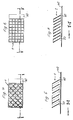
- Fig. 3 shows a manufacturing method for sun protection elements according to the invention, e.g. acc. Fig. 4.
- a clay strand 20 is extruded from an extrusion die of a press 10, which would result in normal hollow blocks in cuts perpendicular to the direction of ejection.
- a miter cut is now carried out at a (variable, adapted to the respective intended use) cutting angle ⁇ to the flow direction A, so that sun protection elements according to the invention are produced which have flat, mutually parallel bottom and top surfaces and contain oblique hollow cylinders.
- FIG. 4 shows a plan view of a further embodiment of a sun protection element that can be produced using the method according to FIG. 3, and FIG. 5 shows a section X-X through FIG. 4.
- Fig. 6 shows yet another embodiment with a different orientation of the surface edges of the cylindrical hollow cylinder, but with the same axis orientation and Fig. 7 is a section on the line X'-X 'of FIG. 6th
- the partial sun protection elements in particular those made of clay, can also be provided with a lime paint to reduce the effect of the sun's rays.
Description
Die Erfindung betrifft ein Verfahren zur Herstellung eines, als Sonnenschutz-Teilelement dienenden, oben und unten offenen, schiefen Hohlzylinders.The invention relates to a method for producing an oblique hollow cylinder, which serves as a partial sun protection element and is open at the top and bottom.
Aus der FR-A-2 287 557 ist ein Verfahren zur Herstellung von Sonnenschutzelementen bekannt.From FR-A-2 287 557 a method for producing sun protection elements is known.
Die Erfindung stellt sich die Aufgabe, ein entsprechendes Herstellungsverfahren derart weiterzuentwickeln, daß auf einfache Weise und mit einfachen Mitteln ein wirksames Sonnenschutz-Teilelement erzeugt werden kann.The object of the invention is to further develop a corresponding manufacturing process in such a way that an effective partial sun protection element can be produced in a simple manner and with simple means.
Diese Aufgabe wird gemäß der Erfindung dadurch gelöst, daß als Ausgangsmaterial Ton verwendet wird, der Ton in einem zylindrischen Hohlstrange extrudiert wird und die Einzelelemente durch einen oder zwei Gehrungsschnitte abgetrennt werden.This object is achieved according to the invention in that clay is used as the starting material, the clay is extruded in a cylindrical hollow strand and the individual elements are separated by one or two miter cuts.
Insbesondere in südlichen Ländern, aber auch in mitteleuropäischen Breiten, besteht das Bedürfnis, Terrassen, Dächer, Schwimmbecken und dgl. vor einer direkten Sonneneinstrahlung zu schützen, insbesondere um eine übermäßige Bestrahlung und eine Erhitzung der Baukörper zu vermeiden.In southern countries in particular, but also in Central European latitudes, there is a need to protect terraces, roofs, swimming pools and the like from direct sunlight, in particular in order to avoid excessive radiation and heating of the structures.
Andererseits soll der Zutritt von Luft und Licht auch nicht unnötig behindert werden, sowie ggfs. der Abfluß von Regenwasser ermöglicht und eine unnötige Belastung einer Abschirmung durch Schnee vermieden werden.On the other hand, the access of air and light should not be unnecessarily hindered, the drainage of rainwater should be made possible and an unnecessary load on a shield by snow should be avoided.
Ton ist ein in ungebranntem Zustand verhältnismäßig leicht zu formendes Material, das sich gebrannt als Baustoff bewährt hat.Clay is a material that is relatively easy to form in the unfired state and has proven itself as a building material when fired.
In der FR-A-2 287 557, die Sonnenschutz-Gesamtelemente betrifft, ist das Herstellungsverfahren nicht näher erläutert. Als Materialien sind pauschal "beton, bois, metal, ou tout autres materiaux plastic ou derivée" genannt.The manufacturing process is not explained in more detail in FR-A-2 287 557, which relates to overall sun protection elements. The materials used are "concrete, bois, metal, ou tout autres materiaux plastic ou derivée".
In der US-A-2 441 819 sind nur "rubber, plastic material, waterproof fabric or synthetic material" angegeben.In US-A-2 441 819 only "rubber, plastic material, waterproof fabric or synthetic material" is specified.
Die FR-A- 1 463 000 zeigt eine lamellenartige Gesamtanordnung.FR-A-1 463 000 shows an overall lamellar arrangement.
Die (sich ergebende) schiefzylindrische Gestalt des erfindungsgemäßen Teilelementes erlaubt durch entsprechende Ausrichtung des schiefen Zylinders eine jeweilige Anpassung an die Haupt-Sonneneinfallsrichtung des Anwendungsortes.The (resulting) oblique-cylindrical shape of the partial element according to the invention permits a respective adaptation to the main direction of sunshine of the application site by appropriate alignment of the oblique cylinder.
Unter einem schiefen Zylinder wird, wie üblich, ein Zylinder verstanden, bei dem zumindest eine der beiden Abschlußflächen, die Boden- oder die Deckfläche, nicht senkrecht, d. h. nicht in einem 90°-Winkel, zur Zylinderachse ist.An oblique cylinder is, as usual, a cylinder in which at least one of the two end surfaces, the bottom or the top surface, is not perpendicular, i.e. H. not at a 90 ° angle to the cylinder axis.
Unter Bodenfläche wird hier die (im wesentlichen gedachte; da es sich ja um einen Hohlzylinder handelt, nur als Ringfläche vorhandene) Fläche verstanden, die der zu schützenden Fläche zugewandt ist, während die Deckfläche die andere Fläche ist.Bottom surface is understood here to mean the (essentially imagined; since it is a hollow cylinder, only existing as an annular surface) surface which faces the surface to be protected, while the top surface is the other surface.
Bevorzugt wird der extrudierte Strang so bemessen, daß beim getrockneten oder gebrannten Endprodukt die, ggfs. anteilige, Querschnittsfläche der Zylinderwand 1/60 bis 1/10 der Querschnittsfläche des Hohlraums beträgt. In besonderen Fällen liegt das Verhältnis zwischen 1/10 und 1/4. D. h. es soll sich um verhältnismäßig dünnwandige Zylinder handeln.The extruded strand is preferably dimensioned such that the cross-sectional area of the cylinder wall, which may be proportional, is 1/60 to 1/10 of the cross-sectional area of the cavity in the dried or fired end product. In special cases the ratio is between 1/10 and 1/4. That is, it should be relatively thin-walled cylinders.
Dadurch wird die Lichtabschirmwirkung nicht beeinträchtigt, die zusätzliche statische Belastung durch die Sonnenschutzmaßnahmen kann aber gering gehalten werden.This does not affect the light shielding effect, but the additional static load from the sun protection measures can be kept low.
Unter Querschnittsfläche wird jeweils die Fläche eines Schnittes verstanden, der senkrecht zur Zylinderachse liegt.Cross-sectional area is understood to mean the area of a cut that is perpendicular to the cylinder axis.
Das Wort "anteilige" ist eingefügt, weil, wie unten noch erläutert wird, ggfs. mehrere derartige Hohlzylinder ein einstückiges Gebilde bilden.The word "proportionate" is inserted because, as will be explained below, several hollow cylinders of this type may form an integral structure.
Bevorzugt wird der Abstand der Gehrungsschnitte so bemessen, daß die Länge der Achse des getrockneten oder gebrannten Zylinders das 1- bis 20-fache der Wurzel aus der Querschnittsfläche des Hohlraums beträgt. Dadurch kann für unterschiedliche Sonneneinfallswinkel zuverlässig eine direkte Bestrahlung der unter dem Hohlzylinder angeordneten Fläche verhindert werden.The distance between the miter cuts is preferably such that the length of the axis of the dried or fired cylinder is 1 to 20 times the root of the cross-sectional area of the cavity. Direct irradiation of the surface arranged under the hollow cylinder can thereby be reliably prevented for different angles of incidence of the sun.
Unter der Achse des Zylinders wird (auch bei nicht parallelen Boden- und Deckflächen) die Verbindung der Flächenschwerpunkte der den Hohlraum abdeckenden gedachten Boden- und Deckflächen verstanden.The axis of the cylinder is understood (even in the case of non-parallel floor and cover surfaces) to be the connection of the centroids of the imaginary floor and cover surfaces covering the cavity.
Bevorzugt wird der Gehrungswinkel so bemessen, daß die Bodenfläche des Zylinders einen Winkel zu einer auf der Zylinderachse senkrechten Ebene aufweist, der ungefähr gleich dem Winkel der vor der Sonne zu schützenden Fläche zur horizontalen Ebene ist.The miter angle is preferably dimensioned such that the bottom surface of the cylinder has an angle to a plane perpendicular to the cylinder axis which is approximately equal to the angle of the surface to be protected from the sun to the horizontal plane.
Dann ist, bei zur Horizontalen senkrechter, also lotrechter, Achse des Zylinders, die Bodenfläche zumindest ungefähr parallel zu der zu schützenden Fläche angeordnet.Then, with the axis of the cylinder perpendicular to the horizontal, that is perpendicular, the bottom surface is arranged at least approximately parallel to the surface to be protected.
Bevorzugt sind die Gehrungswinkel zweier den Hohlzylinder erzeugender Gehrungsschnitte gleich.The miter angles of two miter cuts producing the hollow cylinder are preferably the same.
Bevorzugt hat der Zylinder durch die Gehrungsschnitte zumindest eine schiefe Deckfläche. Er wird dann, bei (zur Horizontalen) senkrechter (also lotrechter) Achse, so angeordnet, daß die höchste Stelle des Mantels von der Achse gesehen in Richtung des höchsten mittleren Sonnenstandes weist.Because of the miter cuts, the cylinder preferably has at least one oblique top surface. It is then arranged with the axis vertical (ie vertical) so that the highest point of the mantle, viewed from the axis, points in the direction of the highest average position of the sun.
Bevorzugt sind die Gehrungswinkel zweier den Hohlzylinder erzeugender Gehrungsschnitte gleich.The miter angles of two miter cuts producing the hollow cylinder are preferably the same.
Dadurch weist der Hohlzylinder eine schiefe Bodenfläche und eine dazu parallele Deckfläche auf, wobei zweckmäßig die Bodenfläche parallel zur vor Sonne zu schützenden Fläche angeordnet wird und die Zylinderachse so angeordnet wird, daß sie nach Norden weist.As a result, the hollow cylinder has an inclined base surface and a cover surface parallel to it, the base surface advantageously being arranged parallel to the surface to be protected from the sun and the cylinder axis being arranged such that it faces north.
Dadurch läßt sich auch in Gegenden mit sehr hohem Sonnenstand sicher eine Direktbestrahlung der zu schützenden Fläche durch die Sonne vermeiden.As a result, direct exposure of the area to be protected by the sun can be safely avoided even in areas with a very high position of the sun.
Bevorzugt weist der Extrusionsstrang mehrere parallele Hohlzylinder auf.The extrusion strand preferably has a plurality of parallel hollow cylinders.
Besonders bevorzugt ist das Sonnenschutzelement ein Hohlziegel mit rechteckiger Grundfläche. Ein solcher Hohlziegel läßt sich im wesentlichen unter Verwendung von Techniken herstellen und verbauen, die auch bei den bekannten Hohlziegeln angewandt werden.The sun protection element is particularly preferably a hollow brick with a rectangular base area. Such a hollow brick can essentially be produced and installed using techniques which are also used in the known hollow bricks.
Bevorzugt wird beim Trennschnitt eine unebene Kante erzeugt.An uneven edge is preferably produced in the separating cut.
Die unebene Kante kann eine unregelmäßige Unebenheit, aber auch eine sägezahnartige, gewellte oder mit kleinen Stützen versehene Form der Bodenfläche sein.The uneven edge can be an irregular unevenness, but it can also be a sawtooth-like, corrugated or with small supports of the bottom surface.
Damit läßt sich auf einfache Weise ein gewisser Abstand der Sonnenschutzelemente von der durch sie zu schützenden Fläche erzielen. Dadurch wird ein Wärmeübergang erschwert und es ist z. B. möglich, daß das in die ja oben und unten offenen Hohlräume eindringende Regenwasser ungehindert wieder abfließen kann.A certain distance of the sun protection elements from the surface to be protected by them can thus be achieved in a simple manner. This makes heat transfer difficult and it is e.g. B. possible that the rainwater penetrating into the cavities open at the top and bottom can flow freely again.
Die Erfindung betrifft auch ein Sonnenschutzelement, bei dem mehrere gleichartige, oben und unten offene, schiefe Hohlzylinder zu einem Gesamtelement verbunden sind. Ein solches Sonnenschutzelement ist, zumindest im Ergebnis, aus der FR-A-2 287 557 bekannt.The invention also relates to a sun protection element in which several oblique hollow cylinders of the same type, open at the top and bottom, are connected to form an overall element. Such a sun protection element is known, at least as a result, from FR-A-2 287 557.
Ein solches Sonnenschutzelement soll verbessert und insbesondere den Verhältnissen in denjenigen Ländern, in denen es vorwiegend angewandt wird, angepaßt werden.Such a sun protection element is to be improved and, in particular, to be adapted to the conditions in those countries in which it is predominantly used.
Dies wird dadurch erreicht, daß die Zylinder aus Ton bestehen, der in einem zylindrischen Hohlstrange extrudiert wurde und wobei die Zylinder durch einen oder zwei Gehrungsschnitte abgetrennt wurden, und die gleichartigen Zylinder zu einem Gesamtelement verbacken sind.This is achieved in that the cylinders consist of clay which has been extruded in a cylindrical hollow strand and the cylinders have been separated by one or two miter cuts, and the similar cylinders are baked to form an overall element.
Wie an sich bekannt, ist es zweckmäßig, für Baumaßnahmen ggfs. auch größere Sonnenschutzelemente zur Hand zu haben, die als Einheit gehandhabt und entsprechend leicht angebracht werden können.As is known per se, it is expedient to also have larger sun protection elements at hand for construction measures, which can be handled as a unit and correspondingly easily attached.
Bevorzugt weisen die verbackenen Hohlzylinder parallele Boden- und Deckenflächen sowie gleiche Achslängen auf und sind so verbacken, daß die Boden- bzw. Deckenflächen jeweils in einer Ebene liegen.The baked hollow cylinders preferably have parallel floor and ceiling surfaces and the same axis lengths and are baked in such a way that the floor and ceiling surfaces each lie in one plane.
Auf diese Weise können mit einer größeren Anzahl Hohlzylindern flächige Gebilde geschaffen werden, die insgesamt eine einheitliche Höhe und parallele Boden- und Deckflächen haben. Diese können dann auf Dachflächen verlegt oder z. B. über Kopfhöhe über Terrassen angebracht werden.In this way, flat structures can be created with a larger number of hollow cylinders, which overall have a uniform height and parallel bottom and top surfaces. These can then be laid on roof areas or z. B. be installed above head height over terraces.
Nachfolgend wird die Erfindung anhand bevorzugter Ausführungsbeispiele unter Bezugnahme auf die beigefügten Zeichnungen, auf die bzgl. der Offenbarung ausdrücklich verwiesen wird, noch näher erläutert.The invention is explained in more detail below on the basis of preferred exemplary embodiments with reference to the accompanying drawings, to which express reference is made to the disclosure.
Es zeigen:
- Fig. 1:
- Schematisch ein Sonnenschutzelement aus drei Sonnenschutz-Teilelementen, im Schnitt;
- Fig. 2:
- Schematisch eine Aufsicht auf ein Sonnenschutzelement aus acht Sonnenschutz-Teilelementen mit achteckigem bzw. viereckigem Querschnitt;
- Fig. 3:
- Schematisch einen Verfahrensschritt zur Herstellung von Sonnenschutzelementen gemäß der Erfindung;
- Fig. 4:
- Eine Aufsicht auf ein Sonnenschutzelement mit rechteckiger Grundfläche, das einstückig aus schiefen Hohlzylindern mit viereckigem bzw. dreieckigem Querschnitt aufgebaut ist;
- Fig. 5:
- Einen Schnitt an der Linie X-X der Fig. 4;
- Fig. 6:
- Ein Sonnenschutzelement, das integral aus gleichartigen Zylindern mit rechteckigem Querschnitt aufgebaut ist;
- Fig. 7:
- Einen Schnitt an der Linie X′-X′ der Fig. 6.
- Fig. 1:
- Schematically a sun protection element from three sun protection sub-elements, in section;
- Fig. 2:
- Schematic is a top view of a sun protection element made up of eight partial sun protection elements with an octagonal or square cross section;
- Fig. 3:
- Schematically a process step for the production of sun protection elements according to the invention;
- Fig. 4:
- A top view of a sun protection element with a rectangular base, which is constructed in one piece from oblique hollow cylinders with a square or triangular cross section;
- Fig. 5:
- A section on the line XX of Fig. 4;
- Fig. 6:
- A sun protection element which is integrally constructed from cylinders of the same type with a rectangular cross section;
- Fig. 7:
- A section on the line X'-X 'of FIG. 6.
Fig. 1 zeigt im Schnitt drei erfindungsgemäße Sonnenschutz-Teilelemente 2, 4, 6, die integral oder einstückig zu einem Sonnenschutzelement 1 verbunden sind.1 shows in section three partial
Die Teilelemente 2, 4, 6 haben achteckige Bodenflächen 12, 14, 16 und achteckige, dazu parallele Deckflächen 22, 24, 26. Die jeweiligen Mittelachsen sind bei 32 bzw. 34 bzw. 36 angedeutet und stehen unter einem Winkel α, im Ausführungsbeispiel von 60°, zu den Boden- und Deckflächen.The
Das gesamte Sonnenschutzelement (auch aus Fig. 2 ersichtlich) ist auf der Dachfläche 40 etwas im Abstand von der Dachfläche 40 mittels Zwischenstücken, z.B. Kunststoffsupporten, gelagert, von denen in Fig. 1 die Zwischenstücke 50 bzw. 60 sichtbar sind. Der Einfall der Sonnenstrahlen ist bei 70 angedeutet und deren Einfallswinkel γ auf die Deckflächen sei für einen vorgegebenen Ort der maximale Einfallswinkel. Die (immer) im Schatten verbleibenden Bereiche der Hohlzylinder sind schraffiert und es zeigt sich insbesondere, daß bei der entsprechenden Wahl der Höhe h, des Winkels der Zylinderachse α zur Bodenfläche und dem Durchmesser der Teilelemente, hier 1/3 a, das Dach von den Sonnenstrahlen nicht mehr getroffen wird. Dies wird auch dadurch erreicht, daß die Zylinderachsen nach Norden ausgerichtet sind.The entire sun protection element (also shown in Fig. 2) is on the
Entsprechend kann auch eine Terrasse, die sich dann eben in größerem Abstand von den Teilelementen 2 bzw. 4 bzw. 6 als das Dach 40 befände, vor direkter Sonneneinstrahlung geschützt werden.Accordingly, a terrace, which would then be located at a greater distance from the
Die Fig. 2 zeigt eine Aufsicht auf das Sonnenschutzelement der Fig. 1, wobei gleiche bzw. entsprechende Elemente mit den gleichen Bezugszeichen versehen sind. An der Linie X-X ist der Schnitt für Fig. 1 angedeutet.FIG. 2 shows a top view of the sun protection element of FIG. 1, the same or corresponding elements being provided with the same reference symbols. The section for Fig. 1 is indicated on the line X-X.
Aus Fig. 2 ist ersichtlich, daß das Teilelement zusätzlich zu den Hohlzylindern 2, 4 und 6 noch ebenfalls achteckige Hohlzylinder 3, 5 und 7 aufweist, die allerdings mit den Hohlzylindern 2, 4 und 6 - wie diese untereinander - einstückig durch teilweise gemeinsame Wände ausgebildet sind.From Fig. 2 it can be seen that the sub-element in addition to the
Durch die Zusammensetzung der regelmäßig achteckigen Form der Boden- und Deckflächen entstehen auch zusätzliche Hohlzylinder 8 und 9 mit quadratischen Boden- bzw. Deckflächen. Solche zusätzlichen Hohlzylinder entstehen auch beim Zusammensetzen mehrerer Sonnenschutzelemente der Fig. 2 zu einer flächigen Sonnenschutzabdeckung.The composition of the regular octagonal shape of the floor and top surfaces also creates additional hollow cylinders 8 and 9 with square bottom and top surfaces. Such additional hollow cylinders also arise when several sun protection elements of FIG. 2 are put together to form a flat sun protection cover.
Fig. 3 zeigt ein erfindungsgemäßes Herstellungsverfahren für Sonnenschutzelemente, z.B. gem. Fig. 4. Aus einer Extrusionsdüse einer Presse 10 wird ein Tonstrang 20 extrudiert, der bei Schnitten senkrecht zur Ausstoßrichtung normale Hohlblocksteine ergäbe. Gemäß der Erfindung wird nun unter einem (variablen, dem jeweiligen Verwendungszweck angepaßten) Schnittwinkel β zur Fließrichtung A ein Gehrungsschnitt durchgeführt, so daß erfindungsgemäße Sonnenschutzelemente entstehen, die ebene, zueinander parallele Boden- und Deckflächen aufweisen und schiefe Hohlzylinder enthalten.Fig. 3 shows a manufacturing method for sun protection elements according to the invention, e.g. acc. Fig. 4. A
Fig. 4 zeigt eine Aufsicht auf eine weitere Ausführungsform eines Sonnenschutzelementes, das mit dem Verfahren nach Fig. 3 herstellbar ist und Fig. 5 zeigt einen Schnitt X-X durch Fig. 4.FIG. 4 shows a plan view of a further embodiment of a sun protection element that can be produced using the method according to FIG. 3, and FIG. 5 shows a section X-X through FIG. 4.
Fig. 6 zeigt noch eine weitere Ausführungsform mit einer anderen Ausrichtung der Flächenkanten der zylindrischen Hohlzylinder, jedoch bei gleicher Achsausrichtung und Fig. 7 einen Schnitt an der Linie X′-X′ der Fig. 6.Fig. 6 shows yet another embodiment with a different orientation of the surface edges of the cylindrical hollow cylinder, but with the same axis orientation and Fig. 7 is a section on the line X'-X 'of FIG. 6th
Die Sonnenschutz-Teilelemente, insbesondere solche aus Ton, können noch mit einem Kalkanstrich versehen sein, um die Auswirkung der Sonnenstrahlen zu reduzieren.The partial sun protection elements, in particular those made of clay, can also be provided with a lime paint to reduce the effect of the sun's rays.
Um die Sonnenschutzelemente auch auf gewölbten Bedachungen, bspw. von Werkhallen, anzubringen, können sie an der Außenseite mit einem verzinkten Drahtnetz befestigt werden.In order to attach the sun protection elements to arched roofs, e.g. in workshops, they can be attached to the outside with a galvanized wire mesh.
Claims (11)
- A process for producing an inclined hollow cylinder open at the top and bottom and acting as a sun-protection partial member, characterized in that clay is used as the starting material, the clay is extruded in a cylindrical hollow billet and the individual members are separated by one or two mitre cuts.
- A process according to claim 1, characterized in that the extruded billet is so dimensioned that, with a dried or fired end product, the possibly shared cross-sectional area of the cylinder wall amounts to from 1/60 to 1/10 of the cross-sectional area of the hollow space.
- A process according to claim 1 or claim 2, characterized in that the distance between the mitre cuts is such that the length of the axis of the dried or fired cylinder amounts to from 1 to 20 times the root of the cross-sectional area of the hollow space.
- A process according to any one of claims 1 to 3, characterized in that the mitre angle is such that the base area of the cylinder forms an angle with a plane perpendicular to the cylinder axis which is approximately equal to the angle between the sun-protection area and the horizontal plane.
- A process according to any one of claims 1 to 4, characterized in that the mitre angles of two mitre cuts generating the hollow cylinder are equal.
- A process according to any one of the preceding claims, characterized in that the extrusion billet comprises several parallel hollow cylinders.
- A process according to any one of the preceding claims, characterized in that an uneven edge is produced during the separating cut.
- A sun-protection element, in which a plurality of like, inclined hollow cylinders open at the top and bottom are connected to form a whole element, characterized in that the cylinders consist of clay which has been extruded in a cylindrical hollow billet, the cylinders being separated by one or two mitre cuts and the like cylinders being fired to form a whole element.
- A sun-protection element according to claim 8, characterized in that the fired hollow cylinders have parallel base and cover surfaces as well as the same axial lengths and are fired in such a way that the base and cover surfaces lie in one plane.
- A sun-protection element according to claim 8 or claim 9, characterized in that the shared cross-sectional area of the walls of the sun-protection element amounts to from 1/60 to 1/10 of the cross-sectional area of the hollow spaces.
- A sun-protection element according to any one of claims 8 to 10, characterized in that the axial length of the cylinders amounts to from one to twenty times the root of the cross-sectional area of the respective hollow space.
Applications Claiming Priority (2)
| Application Number | Priority Date | Filing Date | Title |
|---|---|---|---|
| DE19904028958 DE4028958C1 (en) | 1990-09-12 | 1990-09-12 | |
| DE4028958 | 1990-09-12 |
Publications (2)
| Publication Number | Publication Date |
|---|---|
| EP0477687A1 EP0477687A1 (en) | 1992-04-01 |
| EP0477687B1 true EP0477687B1 (en) | 1994-06-01 |
Family
ID=6414118
Family Applications (1)
| Application Number | Title | Priority Date | Filing Date |
|---|---|---|---|
| EP19910115466 Expired - Lifetime EP0477687B1 (en) | 1990-09-12 | 1991-09-12 | Method and device for the protection of roofs, terraces and the like from the sun |
Country Status (3)
| Country | Link |
|---|---|
| EP (1) | EP0477687B1 (en) |
| DE (1) | DE4028958C1 (en) |
| ES (1) | ES2055951T3 (en) |
Families Citing this family (3)
| Publication number | Priority date | Publication date | Assignee | Title |
|---|---|---|---|---|
| CH687214A5 (en) * | 1994-02-28 | 1996-10-15 | Dietrich Schwarz | Translucent wall sheet. |
| DE19811444A1 (en) * | 1998-03-17 | 1999-09-30 | Gregor Hellenthal | Shading device |
| DE102006030244A1 (en) * | 2006-06-30 | 2008-01-03 | Fraunhofer-Gesellschaft zur Förderung der angewandten Forschung e.V. | Semitransparent static sunscreen |
Family Cites Families (8)
| Publication number | Priority date | Publication date | Assignee | Title |
|---|---|---|---|---|
| US2441819A (en) * | 1945-04-04 | 1948-05-18 | Herbert R Jensen | Ventilating body or screen |
| US3086629A (en) * | 1959-07-08 | 1963-04-23 | Blitzer Bud | Structural panels and elements thereof |
| US3191729A (en) * | 1964-06-01 | 1965-06-29 | Lemual G Brown | Grille or screen |
| DE1509673A1 (en) * | 1965-02-06 | 1969-02-20 | Roberto Merlo | Assemblable parts for making a sun-breaking grid and related connecting elements |
| FR1463000A (en) * | 1965-07-16 | 1966-06-03 | Jaeger Sa | screen |
| FR1488264A (en) * | 1966-03-10 | 1967-07-13 | Fixed louvers with natural light recovery | |
| FR2287557A1 (en) * | 1974-10-08 | 1976-05-07 | Romney Emile | Sun protection partition for walls - gives either complete or partial protection horizontally or vertically |
| DE3500768A1 (en) * | 1985-01-11 | 1986-07-17 | Josef Gartner & Co, 8883 Gundelfingen | Sunshade |
-
1990
- 1990-09-12 DE DE19904028958 patent/DE4028958C1/de not_active Expired - Fee Related
-
1991
- 1991-09-12 EP EP19910115466 patent/EP0477687B1/en not_active Expired - Lifetime
- 1991-09-12 ES ES91115466T patent/ES2055951T3/en not_active Expired - Lifetime
Also Published As
| Publication number | Publication date |
|---|---|
| DE4028958C1 (en) | 1992-02-27 |
| ES2055951T3 (en) | 1994-09-01 |
| EP0477687A1 (en) | 1992-04-01 |
Similar Documents
| Publication | Publication Date | Title |
|---|---|---|
| DE19739749A1 (en) | Curtain wall construction | |
| EP0025959A1 (en) | Method for manufacturing a stone panel for surface heating | |
| DE3431208A1 (en) | ROOF VENTILATION | |
| DE60017556T2 (en) | LOST BLOCKING BLOCK UNIT FOR A CONCRETE WALL | |
| DE2842123A1 (en) | FIRST CAP SYSTEM | |
| EP0041181A2 (en) | Curtain wall or building or decorative panel | |
| EP0477687B1 (en) | Method and device for the protection of roofs, terraces and the like from the sun | |
| EP0116153A1 (en) | Protective device for reducing wind velocity | |
| DE2733361A1 (en) | INSTALLATION ELEMENT FOR LIQUID SURFACE HEATING SYSTEMS | |
| DE2934074C2 (en) | Swimming pool | |
| DE60316512T2 (en) | Windproof roof tile | |
| AT390465B (en) | DOUBLE FLOOR WITH A FIRE-RESISTANT LAYER | |
| DE102010034600B4 (en) | Deckle board | |
| DE8608407U1 (en) | Stand base for fence posts or the like. | |
| DE2146286C2 (en) | Weather and privacy shield | |
| DE102020118104B4 (en) | Protection device for building scaffolding | |
| DE2441164C2 (en) | Sound-absorbing wall element | |
| EP0610157A1 (en) | Covering for vertical or sloping outer surfaces of buildings | |
| DE840591C (en) | In the style of Moench and Nun, hollow tile for roofing that can be laid | |
| DE3036620C2 (en) | Device for protecting structural parts made of concrete against moisture | |
| DE3207413C2 (en) | Industrially prefabricated wall element | |
| DE804860C (en) | Transportable greenhouse or the like. | |
| DE19840650A1 (en) | Environmentally friendly noise protection wall for roads etc. is constructed from modules with parallel walls, containing esp. rye straw bales | |
| DE1838423U (en) | DEVICE FOR FASTENING CLADDING PANELS TO WALLS, CEILINGS AND THE LIKE, IN PARTICULAR FOR THE FACADE CLADDING OF BUILDINGS. | |
| EP0593006A1 (en) | Roof covering panel |
Legal Events
| Date | Code | Title | Description |
|---|---|---|---|
| PUAI | Public reference made under article 153(3) epc to a published international application that has entered the european phase |
Free format text: ORIGINAL CODE: 0009012 |
|
| AK | Designated contracting states |
Kind code of ref document: A1 Designated state(s): ES GR IT |
|
| 17P | Request for examination filed |
Effective date: 19920928 |
|
| 17Q | First examination report despatched |
Effective date: 19930215 |
|
| GRAA | (expected) grant |
Free format text: ORIGINAL CODE: 0009210 |
|
| AK | Designated contracting states |
Kind code of ref document: B1 Designated state(s): ES GR IT |
|
| ITF | It: translation for a ep patent filed |
Owner name: BARZANO' E ZANARDO MILANO S.P.A. |
|
| REG | Reference to a national code |
Ref country code: ES Ref legal event code: FG2A Ref document number: 2055951 Country of ref document: ES Kind code of ref document: T3 |
|
| REG | Reference to a national code |
Ref country code: GR Ref legal event code: FG4A Free format text: 3012902 |
|
| PLBE | No opposition filed within time limit |
Free format text: ORIGINAL CODE: 0009261 |
|
| STAA | Information on the status of an ep patent application or granted ep patent |
Free format text: STATUS: NO OPPOSITION FILED WITHIN TIME LIMIT |
|
| 26N | No opposition filed | ||
| PGFP | Annual fee paid to national office [announced via postgrant information from national office to epo] |
Ref country code: GR Payment date: 19960904 Year of fee payment: 6 |
|
| PGFP | Annual fee paid to national office [announced via postgrant information from national office to epo] |
Ref country code: ES Payment date: 19960926 Year of fee payment: 6 |
|
| PG25 | Lapsed in a contracting state [announced via postgrant information from national office to epo] |
Ref country code: ES Free format text: LAPSE BECAUSE OF EXPIRATION OF PROTECTION Effective date: 19970913 |
|
| PG25 | Lapsed in a contracting state [announced via postgrant information from national office to epo] |
Ref country code: GR Free format text: LAPSE BECAUSE OF NON-PAYMENT OF DUE FEES Effective date: 19970930 |
|
| REG | Reference to a national code |
Ref country code: ES Ref legal event code: FD2A Effective date: 20010201 |
|
| PG25 | Lapsed in a contracting state [announced via postgrant information from national office to epo] |
Ref country code: IT Free format text: LAPSE BECAUSE OF NON-PAYMENT OF DUE FEES Effective date: 20050912 |