EP0475181A2 - Flugzeug-höhenmesser - Google Patents
Flugzeug-höhenmesser Download PDFInfo
- Publication number
- EP0475181A2 EP0475181A2 EP91114285A EP91114285A EP0475181A2 EP 0475181 A2 EP0475181 A2 EP 0475181A2 EP 91114285 A EP91114285 A EP 91114285A EP 91114285 A EP91114285 A EP 91114285A EP 0475181 A2 EP0475181 A2 EP 0475181A2
- Authority
- EP
- European Patent Office
- Prior art keywords
- tracking
- altitude
- pulses
- radar
- radar altimeter
- Prior art date
- Legal status (The legal status is an assumption and is not a legal conclusion. Google has not performed a legal analysis and makes no representation as to the accuracy of the status listed.)
- Granted
Links
- 230000008878 coupling Effects 0.000 claims 2
- 238000010168 coupling process Methods 0.000 claims 2
- 238000005859 coupling reaction Methods 0.000 claims 2
- 238000010586 diagram Methods 0.000 description 5
- 230000006870 function Effects 0.000 description 5
- 238000002310 reflectometry Methods 0.000 description 4
- 238000001514 detection method Methods 0.000 description 2
- 230000003321 amplification Effects 0.000 description 1
- 238000006243 chemical reaction Methods 0.000 description 1
- 238000010276 construction Methods 0.000 description 1
- 230000001419 dependent effect Effects 0.000 description 1
- 238000003199 nucleic acid amplification method Methods 0.000 description 1
- XLYOFNOQVPJJNP-UHFFFAOYSA-N water Substances O XLYOFNOQVPJJNP-UHFFFAOYSA-N 0.000 description 1
Images

Classifications
-
- G—PHYSICS
- G01—MEASURING; TESTING
- G01S—RADIO DIRECTION-FINDING; RADIO NAVIGATION; DETERMINING DISTANCE OR VELOCITY BY USE OF RADIO WAVES; LOCATING OR PRESENCE-DETECTING BY USE OF THE REFLECTION OR RERADIATION OF RADIO WAVES; ANALOGOUS ARRANGEMENTS USING OTHER WAVES
- G01S13/00—Systems using the reflection or reradiation of radio waves, e.g. radar systems; Analogous systems using reflection or reradiation of waves whose nature or wavelength is irrelevant or unspecified
- G01S13/88—Radar or analogous systems specially adapted for specific applications
- G01S13/93—Radar or analogous systems specially adapted for specific applications for anti-collision purposes
- G01S13/933—Radar or analogous systems specially adapted for specific applications for anti-collision purposes of aircraft or spacecraft
- G01S13/935—Radar or analogous systems specially adapted for specific applications for anti-collision purposes of aircraft or spacecraft for terrain-avoidance
-
- G—PHYSICS
- G01—MEASURING; TESTING
- G01S—RADIO DIRECTION-FINDING; RADIO NAVIGATION; DETERMINING DISTANCE OR VELOCITY BY USE OF RADIO WAVES; LOCATING OR PRESENCE-DETECTING BY USE OF THE REFLECTION OR RERADIATION OF RADIO WAVES; ANALOGOUS ARRANGEMENTS USING OTHER WAVES
- G01S13/00—Systems using the reflection or reradiation of radio waves, e.g. radar systems; Analogous systems using reflection or reradiation of waves whose nature or wavelength is irrelevant or unspecified
- G01S13/66—Radar-tracking systems; Analogous systems
- G01S13/70—Radar-tracking systems; Analogous systems for range tracking only
-
- G—PHYSICS
- G01—MEASURING; TESTING
- G01S—RADIO DIRECTION-FINDING; RADIO NAVIGATION; DETERMINING DISTANCE OR VELOCITY BY USE OF RADIO WAVES; LOCATING OR PRESENCE-DETECTING BY USE OF THE REFLECTION OR RERADIATION OF RADIO WAVES; ANALOGOUS ARRANGEMENTS USING OTHER WAVES
- G01S13/00—Systems using the reflection or reradiation of radio waves, e.g. radar systems; Analogous systems using reflection or reradiation of waves whose nature or wavelength is irrelevant or unspecified
- G01S13/87—Combinations of radar systems, e.g. primary radar and secondary radar
-
- G—PHYSICS
- G01—MEASURING; TESTING
- G01S—RADIO DIRECTION-FINDING; RADIO NAVIGATION; DETERMINING DISTANCE OR VELOCITY BY USE OF RADIO WAVES; LOCATING OR PRESENCE-DETECTING BY USE OF THE REFLECTION OR RERADIATION OF RADIO WAVES; ANALOGOUS ARRANGEMENTS USING OTHER WAVES
- G01S13/00—Systems using the reflection or reradiation of radio waves, e.g. radar systems; Analogous systems using reflection or reradiation of waves whose nature or wavelength is irrelevant or unspecified
- G01S13/02—Systems using reflection of radio waves, e.g. primary radar systems; Analogous systems
- G01S13/06—Systems determining position data of a target
- G01S13/08—Systems for measuring distance only
- G01S13/10—Systems for measuring distance only using transmission of interrupted, pulse modulated waves
- G01S13/18—Systems for measuring distance only using transmission of interrupted, pulse modulated waves wherein range gates are used
-
- G—PHYSICS
- G01—MEASURING; TESTING
- G01S—RADIO DIRECTION-FINDING; RADIO NAVIGATION; DETERMINING DISTANCE OR VELOCITY BY USE OF RADIO WAVES; LOCATING OR PRESENCE-DETECTING BY USE OF THE REFLECTION OR RERADIATION OF RADIO WAVES; ANALOGOUS ARRANGEMENTS USING OTHER WAVES
- G01S13/00—Systems using the reflection or reradiation of radio waves, e.g. radar systems; Analogous systems using reflection or reradiation of waves whose nature or wavelength is irrelevant or unspecified
- G01S13/88—Radar or analogous systems specially adapted for specific applications
- G01S13/882—Radar or analogous systems specially adapted for specific applications for altimeters
-
- G—PHYSICS
- G01—MEASURING; TESTING
- G01S—RADIO DIRECTION-FINDING; RADIO NAVIGATION; DETERMINING DISTANCE OR VELOCITY BY USE OF RADIO WAVES; LOCATING OR PRESENCE-DETECTING BY USE OF THE REFLECTION OR RERADIATION OF RADIO WAVES; ANALOGOUS ARRANGEMENTS USING OTHER WAVES
- G01S7/00—Details of systems according to groups G01S13/00, G01S15/00, G01S17/00
- G01S7/02—Details of systems according to groups G01S13/00, G01S15/00, G01S17/00 of systems according to group G01S13/00
- G01S7/40—Means for monitoring or calibrating
- G01S7/4004—Means for monitoring or calibrating of parts of a radar system
- G01S7/4008—Means for monitoring or calibrating of parts of a radar system of transmitters
Definitions
- This invention relates generally to apparatus for measuring the altitude of an aircraft above the earth's surface.
- Radar systems are commonly used to implement altimeters for aircraft.
- Such an altimeter typically includes a transmitter for applying pulses of electromagnetic energy at regular intervals to an antenna which then radiates the energy towards the earth's surface.
- the altimeter further includes a signal receiver located in the aircraft for picking up echo or return signals reflected from the earth's surface.
- a closed loop servo tracker for measuring the time interval between the transmitted pulse and its associated return pulse also forms a part of the receiver. The interval is, of course, directly related to the altitude of the aircraft above sea level.
- Prior art radar aircraft altimeters are generally incapable of distinguishing between the earth's surface, be it ground or water, and objects projecting upward from the earth's surface. Specifically, such prior art radar altimeters are incapable of distinguishing between treetops and ground or between man-made objects, such as bridges, towers, etc., and the earth's surface.
- the inventive radar altimeter permits a pilot to more safely maneuver at low altitudes over treetops, bridges and mountainous terrain.
- Simultaneous tracking of multiple targets by a radar altimeter is achieved in accordance with the present invention by providing a radar transmitter and a receiver on the aircraft where the transmitter emits pulses of electromagnetic energy at a predetermined repetition rate towards the earth's surface and the receiver picks up the return pulse signals from the earth's surface and from objects which may be extending upwardly from the earth's surface.
- a closed loop servo tracker which is operative to determine from the time interval between transmitted pulses and the corresponding return pulse signals from the earth's surface, the altitude of the aircraft relative to the earth's surface.
- the receiver monitors the amplitude of the return pulse signals and the rate of change of altitude.
- Forming a part of the tracking loop is a programmed microcontroller which periodically interrupts the tracking of the earth's surface and stores away in its memory the altitude, rate and amplitude information.
- the microcontroller also is programmed for adjusting the gain of the transmitter, causing it to emit higher energy pulses while the receiver searches for returns from objects or obstructions projecting upward from the earth's surface. When such returns are found, the programmed microcontroller reinitiates the tracker to lock onto the return signal from the object.
- the microcontroller switches back to the mode where only the earth's surface is being tracked while searching obstructions.
- both altitude information and forward obstacle avoidance can be achieved.
- the invention described herein is a general altitude range tracking radar, i.e., range is measured and indicated by measuring the time for transmitted energy to be reflected from the surface and returned.
- the radar transmitter repeatedly sends out bursts of electromagnetic energy at a predetermined repetition rate from a relatively wide-beam antenna, as indicated by the transmit pulse 10.
- a ground return pulse 12 is received by a receiving antenna feeding a receiver.
- a second return 14 from objects such as treetops may also be applied to the receiver input.
- the ground reflectivity is considerably greater than that of the treetops, and the aircraft has been flying over ground with no trees, a conventional radar would continue to track the ground as it flies over trees. This is due in part to the automatic transmit power level control maintaining the ground return at a nominal level, thereby reducing the low reflectivity treetop return 14 below the track reference level 16.
- the range between the ground and the treetop return is sufficiently large so that a relatively narrow range gate 20 will never overlap the treetop return 14 while tracking the ground return 12 and, hence, the treetop return will not be reflected as a separate received signal.
- the present invention overcomes these two constraints by periodically interrupting the normal ground track for an insignificantly small time interval so as not to degrade the normal track operation and then searching a short distance above and below the main ground return 12. While performing this search operation on either side of the main return, the automatic transmit power level is disabled, providing maximum transmit power so that the return from the lower reflectivity treetops will cross the track threshold 16. If no secondary target is detected with the transmitter at full power, tracking is continued on the original target. If a secondary target, e.g., treetops, is detected, the two targets are tracked together on a time multiplexed basis.
- FIG. 2 illustrates the components of a radar altimeter designed for multiple target tracking.
- Overall timing and control of the system is achieved by providing a digital control module 22 having a random access memory 24 coupled to the memory port 26 thereof.
- the digital controller 22 is coupled to the radar transmitter 29 via line 28 for establishing the time, T0, at which transmit pulses 10 are generated and applied to the transmitting antenna 30.
- the digital controller 22 also has an output line 32 leading to the transmitter 29 for establishing the amplitude level or power of the transmitted signal.
- the automatic transmit power level control is disabled, thereby providing a maximum transmit power so that the return from the lower reflectivity target, e.g., treetops, will cross the track reference threshold 16.
- the return pulse is picked up by a receiving antenna 34 and is fed through a range gate 36 to the radar altimeter receiver shown enclosed by the broken line box 38.
- the receiver includes conventional amplification, band-limiting down-conversion and peak detection circuitry 40 well known to those skilled in the art.
- the resulting signal is then fed to an A/D converter 44 whose output, in turn, is applied to a threshold detector circuit 42 and a determination is made whether a target is present by establishing whether the return signal exceeds a prescribed threshold.
- a return meeting the prescribed criteria is then fed via bus 46 to the digital controller 22.
- An output from the digital controller on line 48 is applied to the range gate and used to align the range gate with the leading edge of a return pulse.
- the aircraft altitude then, is directly proportional to the delay interval between the time that the transmitter 29 issues its output and the leading edge of the range gate pulse 20 ( Figure 1).
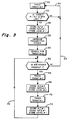
- FIG. 3 there is shown a software flow diagram of the algorithm used by the digital controller 22 for tracking multiple targets.
- the operation can be considered as beginning when the closed loop tracker of the receiver operates to position the range gate in alignment with the leading edge of the strongest return, i.e., that reflected from ground. See block 50 in Figure 3.
- a determination is made whether the aircraft is a greater distance (altitude) relative to ground than some predetermined minimum (block 52). If it is, there is no need to track a second target (treetops) because, presumably, the aircraft is at a high enough altitude that treetops or other obstructions are of no concern to the pilot. Thus, operation loops back via path 54 so that only target 1 (ground) is tracked.
- the digital controller 22 will undertake to store away the altitude of target 1 (ground), the rate in feet per second that the altitude of target 1 is changing and the signal level control voltage on line 32 which establishes the transmitter power for target 1 so that the receiver will appropriately respond. These three operations are represented by block 56 in Figure 3.
- the digital controller 22 provides a signal via line 32 to the transmitter 29 to effectively increase the power of the transmitter (block 58) to its maximum output.
- a search is made for a secondary target (block 60). If no secondary target is detected, control follows the path 64 and only target no. 1 is tracked. However, if decision block 62 reveals that a second target is present, the tracking loop in the receiver will function to position the range gate on the secondary return 14 and the transit time of the transmitted pulse from the transmitter to the secondary target (treetops, bridge, etc.) and back to the receiver will be measured (block 66).
- the altitude of target number 2, its rate of rise or fall and the power level needed to provide a constant amplitude output are stored in the RAM memory 24 (block 68).
- the digital control 22 will again cause the receiver to track target no. 1 with the initial condition for altitude, rate and power level relating thereto being read out from the RAM memory and serving as a starting point for the resumption of tracking of target 1.
- the parameters including altitude, rate of rise and fall and transmitter power level will be stored and control loops back via path 74 to the input of decision block 62 where a decision is again made as to whether there is still a second target present.
- tracking of two targets is time shared so long as a second target is deemed to be present.
- the time shared mechanization results in the capability to search for a target while tracking the surface and then to track both targets simultaneously once two such targets are acquired. By indicating both the surface and obstructions, a pilot can safely maneuver at lower altitudes over treetops, bridges, mountain terrain, etc.
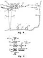
- FIG. 4 an aircraft 100 is represented as flying over ground 102 having objects, such as trees 104 and buildings 106 extending upwardly therefrom. Located out ahead of the aircraft is an obstacle, such as a mountainside 108.
- the aircraft 100 is equipped with a downward looking, relatively wide beam transmitting antenna 110 and a similar receiving antenna 112.
- the path of the transmitted pulses from the downward looking antenna are represented by the arrow 114 while the path of the return signal is represented by arrow 116.
- the radar altimeter of Figure 2 is located in the aircraft 100 and is represented by the box 118.
- a forward-looking antenna 120 which is a relatively narrow beam design and it functions both as a transmitting antenna and a receiving antenna on a time-multiplexed basis.
- the transmitted radar signals are represented by the arrow 122 and the echo or return signals from the forward-looking antenna are represented by the arrow 124.
- Figure 5 illustrates the downward-looking transmitting antenna 110 and receiving antenna 112 as well as the forward-looking transmit/receive antenna 120.
- the transmitter 29 of Figure 2 is adapted to be connected to the downward-looking antenna 110 through an electronic switch or duplexer 128 and, likewise, the receiving antenna 112 is adapted to be coupled to the range gate 36 of Figure 2 by way of the duplexer 130.
- Duplexers 128 and 130 are also connected to a further duplexer 132 such that if the duplexer switches are appropriately positioned, the output of the radar altimeter transmitter 29 can be routed through duplexer 128 and duplexer 132 to the up converter or mixer 134 and through that device to the forward-looking transmit/receive antenna 120.
- the return signal 124 picked up by the antenna 120 will also be fed back through the converter 134 and through the duplexers 132 and 130 to the input to the range gate 36 of Figure 2.
- the size (diameter) of the antenna 120 is a function of the wavelength of the transmitted and receive signals and that because of the constraints of where such an antenna may be placed on an aircraft, there is a practical limit to the physical size that the antenna may assume.
- the up converter 134 By providing the up converter 134, it is possible to obtain a narrow beam width from the antenna 120 while maintaining that antenna a reasonable size. For example, if a beam width of 3° is desired, it can be accomplished with a 7.5" diameter antenna, provided the transmitting frequency is 35 GHz.
- the downward-looking transmitting and receiving antennas 110 and 112 should preferably provide a beam width of about 40° which corresponds to a frequency of 4.3 GHz.
- a 4.3 GHz transmitter can then be used, provided the up converter includes a local oscillator 136 operating at a frequency of 30.7 GHz. It is possible to realize such an oscillator using a Gunn diode as the active element thereof.
- the duplexers 128, 130 and 132 are under control of the digital control 22 of Figure 2 such that following the generation of a transmitter output from the downward-looking transmitting antenna 110, a switch-over of the duplexers will occur such that the return signal picked up by the receive antenna 112 will be fed through the duplexer 130 to the receiver electronics.
- the digital control 22 is effective to switch over the duplexers 132 and 130 such that the return echo picked up by the antenna 120 will be fed through the mixer 134, the duplexer 132 and the duplexer 130 to the receive electronics.
- the system of the present invention can, hence, be used for tracking multiple targets where the targets are located more or less directly below the aircraft or where one target is below the aircraft and the other is forward of the aircraft.
- a local oscillator may be coupled to separate mixers, one for the transmitting channel and one for the receive channel where the forward-looking antenna 120 would be coupled to a duplexer used to route the transmit pulses to the antenna and the received pulses back through its down converter to the receiver channel.
Landscapes
- Engineering & Computer Science (AREA)
- Radar, Positioning & Navigation (AREA)
- Remote Sensing (AREA)
- Physics & Mathematics (AREA)
- Computer Networks & Wireless Communication (AREA)
- General Physics & Mathematics (AREA)
- Aviation & Aerospace Engineering (AREA)
- Electromagnetism (AREA)
- Radar Systems Or Details Thereof (AREA)
Applications Claiming Priority (2)
| Application Number | Priority Date | Filing Date | Title |
|---|---|---|---|
| US07/574,586 US5047779A (en) | 1990-08-28 | 1990-08-28 | Aircraft radar altimeter with multiple target tracking capability |
| US574586 | 1990-08-28 |
Publications (3)
| Publication Number | Publication Date |
|---|---|
| EP0475181A2 true EP0475181A2 (de) | 1992-03-18 |
| EP0475181A3 EP0475181A3 (en) | 1993-05-26 |
| EP0475181B1 EP0475181B1 (de) | 1996-11-13 |
Family
ID=24296753
Family Applications (1)
| Application Number | Title | Priority Date | Filing Date |
|---|---|---|---|
| EP91114285A Expired - Lifetime EP0475181B1 (de) | 1990-08-28 | 1991-08-26 | Flugzeug-höhenmesser |
Country Status (5)
| Country | Link |
|---|---|
| US (1) | US5047779A (de) |
| EP (1) | EP0475181B1 (de) |
| JP (1) | JP3030791B2 (de) |
| CA (1) | CA2050059C (de) |
| DE (1) | DE69123108T2 (de) |
Cited By (5)
| Publication number | Priority date | Publication date | Assignee | Title |
|---|---|---|---|---|
| WO2001059407A1 (en) * | 2000-02-14 | 2001-08-16 | Saab Dynamics Ab | A plant and a method for navigating a vehicle |
| WO2004111679A1 (en) * | 2003-06-11 | 2004-12-23 | Honeywell International Inc. | Radar altimeter with forward ranging capabilities |
| WO2005001509A1 (en) * | 2003-06-11 | 2005-01-06 | Honeywell International, Inc. | Radar altimeter with forward looking nm-wave terrain avoidance radar |
| WO2005101052A1 (en) * | 2004-04-06 | 2005-10-27 | Honeywell International, Inc. | Method and system for terrain avoidance utilizing radar altimeter, digital elevation maps and forward looking terrain avoidance radar |
| US7777668B2 (en) | 2008-04-08 | 2010-08-17 | Honeywell International Inc. | Radar altimeter with forward looking radar and data transfer capabilities |
Families Citing this family (32)
| Publication number | Priority date | Publication date | Assignee | Title |
|---|---|---|---|---|
| US5160933A (en) * | 1990-08-28 | 1992-11-03 | Honeywell Inc. | Radar altimeter with self-calibration feature |
| JPH0580150A (ja) * | 1991-09-20 | 1993-04-02 | Kawasaki Heavy Ind Ltd | 対地距離測定装置 |
| FR2690754B1 (fr) * | 1992-04-30 | 1994-06-10 | Thomson Csf | Procede de detection et de localisation d'objets sur un sol relativement plan et dispositif de mise en óoeuvre. |
| US5477226A (en) * | 1994-05-09 | 1995-12-19 | Honeywell Inc. | Low cost radar altimeter with accuracy enhancement |
| US5719582A (en) * | 1994-10-21 | 1998-02-17 | Honeywell Inc. | Software/hardware digital signal processing (DSP) altimeter |
| US6204805B1 (en) * | 1998-02-06 | 2001-03-20 | Honeywell Inc. | Dual target tracking altimeter |
| RU2133045C1 (ru) * | 1998-02-23 | 1999-07-10 | Григорьев Владимир Григорьевич | Способ определения дальности |
| CA2390487C (en) * | 2001-06-11 | 2009-02-10 | Robert D. Wiplinger | Gear status indicator aircraft landing system |
| US7486228B2 (en) * | 2006-03-02 | 2009-02-03 | Honeywell International Inc. | Methods and systems for piecewise curve fitting or radar altimeter range gate data |
| DE102006050354A1 (de) * | 2006-10-25 | 2008-04-30 | Siemens Ag | Verfahren und Anordnung zur Leistungssteuerung |
| US7808423B2 (en) * | 2007-04-05 | 2010-10-05 | Honeywell International Inc. | Methods for rapid target acquisitions in range measurement systems |
| US8896480B1 (en) | 2011-09-28 | 2014-11-25 | Rockwell Collins, Inc. | System for and method of displaying an image derived from weather radar data |
| US9733349B1 (en) | 2007-09-06 | 2017-08-15 | Rockwell Collins, Inc. | System for and method of radar data processing for low visibility landing applications |
| US9939526B2 (en) | 2007-09-06 | 2018-04-10 | Rockwell Collins, Inc. | Display system and method using weather radar sensing |
| US8515600B1 (en) * | 2007-09-06 | 2013-08-20 | Rockwell Collins, Inc. | System and method for sensor-based terrain avoidance |
| US8917191B1 (en) | 2011-09-22 | 2014-12-23 | Rockwell Collins, Inc. | Dual threaded system for low visibility operations |
| US9354633B1 (en) | 2008-10-31 | 2016-05-31 | Rockwell Collins, Inc. | System and method for ground navigation |
| FR2950149B1 (fr) * | 2009-09-17 | 2012-08-17 | Mbda France | Procede et systeme d'evitement d'un engin d'interception par un mobile aerien |
| DE102010012071B4 (de) * | 2010-03-19 | 2013-04-04 | Airbus Operations Gmbh | Verfahren und System zur Steuerung einer Flugzeugkomponente bei einer Wasserlandung |
| FR2972537B1 (fr) * | 2011-03-11 | 2014-08-22 | Eurocopter France | Procede de mesure de hauteur et de detection d'obstacle, radioaltimetre et aeronef |
| WO2013119151A1 (en) * | 2012-02-08 | 2013-08-15 | Saab Ab | A method for variable control of a zone sensor in a combat aircraft. |
| IN2014DN03126A (de) * | 2012-02-16 | 2015-05-22 | Saab Ab | |
| US9081094B2 (en) * | 2012-02-22 | 2015-07-14 | Honeywell International Inc. | Aircraft radar altimeter structure |
| US9116239B1 (en) * | 2013-01-14 | 2015-08-25 | Rockwell Collins, Inc. | Low range altimeter antenna |
| US9998202B2 (en) | 2013-03-15 | 2018-06-12 | Smartsky Networks LLC | Position information assisted beamforming |
| US9262932B1 (en) | 2013-04-05 | 2016-02-16 | Rockwell Collins, Inc. | Extended runway centerline systems and methods |
| US10928510B1 (en) | 2014-09-10 | 2021-02-23 | Rockwell Collins, Inc. | System for and method of image processing for low visibility landing applications |
| US10705201B1 (en) | 2015-08-31 | 2020-07-07 | Rockwell Collins, Inc. | Radar beam sharpening system and method |
| US10228460B1 (en) | 2016-05-26 | 2019-03-12 | Rockwell Collins, Inc. | Weather radar enabled low visibility operation system and method |
| US10353068B1 (en) | 2016-07-28 | 2019-07-16 | Rockwell Collins, Inc. | Weather radar enabled offshore operation system and method |
| US10989802B2 (en) * | 2017-10-12 | 2021-04-27 | Honeywell International Inc. | Altimeter with high-resolution radar |
| TR202013126A2 (tr) * | 2020-08-19 | 2022-03-21 | Roketsan Roket Sanayi Ve Ticaret Anonim Sirketi | Mi̇krodalga alti̇metreli̇ algilayici si̇stemi̇ ve yöntemi̇ |
Family Cites Families (10)
| Publication number | Priority date | Publication date | Assignee | Title |
|---|---|---|---|---|
| US3739379A (en) * | 1971-02-03 | 1973-06-12 | Hoffman Electronics Corp | Coherent pulse doppler altimeter |
| US4023171A (en) * | 1975-11-12 | 1977-05-10 | The Singer Company | Microwave velocity sensor using altimeter echo |
| US4144571A (en) * | 1977-03-15 | 1979-03-13 | E-Systems, Inc. | Vehicle guidance system |
| US4174520A (en) * | 1978-02-13 | 1979-11-13 | Canadian Patents & Development Limited | Radar altimeter for tropical areas |
| US4320397A (en) * | 1979-06-29 | 1982-03-16 | Nasa | Echo tracker/range finder for radars and sonars |
| FR2579760B1 (fr) * | 1985-03-29 | 1987-05-15 | Trt Telecom Radio Electr | Dispositif pour mesurer la vitesse de defilement d'une surface |
| US4698635A (en) * | 1986-03-02 | 1987-10-06 | The United States Of America As Represented By The Secretary Of The Navy | Radar guidance system |
| US4758839A (en) * | 1987-07-22 | 1988-07-19 | Mcdonnell Douglas Corporation | Terrain profile radar system |
| US4806935A (en) * | 1987-09-17 | 1989-02-21 | Fosket Timothy G | Closed loop velocity/altitude sensor for FM-CW doppler radars |
| EP0311312A3 (de) * | 1987-10-07 | 1990-12-12 | Smiths Industries Public Limited Company | Radar-Höhenmesssysteme |
-
1990
- 1990-08-28 US US07/574,586 patent/US5047779A/en not_active Expired - Lifetime
-
1991
- 1991-08-26 EP EP91114285A patent/EP0475181B1/de not_active Expired - Lifetime
- 1991-08-26 DE DE69123108T patent/DE69123108T2/de not_active Expired - Fee Related
- 1991-08-27 CA CA002050059A patent/CA2050059C/en not_active Expired - Fee Related
- 1991-08-28 JP JP3240308A patent/JP3030791B2/ja not_active Expired - Fee Related
Cited By (7)
| Publication number | Priority date | Publication date | Assignee | Title |
|---|---|---|---|---|
| WO2001059407A1 (en) * | 2000-02-14 | 2001-08-16 | Saab Dynamics Ab | A plant and a method for navigating a vehicle |
| US6725153B2 (en) | 2000-02-14 | 2004-04-20 | Saab Ab | System and a method for navigating a vehicle |
| WO2004111679A1 (en) * | 2003-06-11 | 2004-12-23 | Honeywell International Inc. | Radar altimeter with forward ranging capabilities |
| WO2005001509A1 (en) * | 2003-06-11 | 2005-01-06 | Honeywell International, Inc. | Radar altimeter with forward looking nm-wave terrain avoidance radar |
| US6897803B2 (en) | 2003-06-11 | 2005-05-24 | Honeywell International Inc. | Radar altimeter with forward ranging capabilities |
| WO2005101052A1 (en) * | 2004-04-06 | 2005-10-27 | Honeywell International, Inc. | Method and system for terrain avoidance utilizing radar altimeter, digital elevation maps and forward looking terrain avoidance radar |
| US7777668B2 (en) | 2008-04-08 | 2010-08-17 | Honeywell International Inc. | Radar altimeter with forward looking radar and data transfer capabilities |
Also Published As
| Publication number | Publication date |
|---|---|
| CA2050059A1 (en) | 1992-03-01 |
| EP0475181B1 (de) | 1996-11-13 |
| EP0475181A3 (en) | 1993-05-26 |
| DE69123108T2 (de) | 1997-05-15 |
| US5047779A (en) | 1991-09-10 |
| CA2050059C (en) | 2001-02-27 |
| JPH04254781A (ja) | 1992-09-10 |
| DE69123108D1 (de) | 1996-12-19 |
| JP3030791B2 (ja) | 2000-04-10 |
Similar Documents
| Publication | Publication Date | Title |
|---|---|---|
| US5047779A (en) | Aircraft radar altimeter with multiple target tracking capability | |
| US4170773A (en) | Precision approach sensor system for aircraft | |
| EP0321877B1 (de) | Wetterradar mit Turbulenzdetektion | |
| EP1631837B1 (de) | Radar-höhenmesser mit zusätzlich vorwärts gerichteter entfernungsmessung | |
| US4897660A (en) | Structure resonant radar detection apparatus and method | |
| US5097269A (en) | Multistatic radar systems | |
| US20090243911A1 (en) | Method and device for positioning aircraft, such as for automatic guiding during the landing phase | |
| US6750807B1 (en) | Radar altimeter with forward obstacle avoidance capabilities | |
| US6414622B1 (en) | Anti-radar missile (ARM) countermeasure method | |
| US3277467A (en) | Time sharing radar-altimeter | |
| US3246322A (en) | Distance measuring equipment | |
| GB2032723A (en) | Synthetic aperture radar | |
| US3713147A (en) | Obstacle detection with crossed fan beam | |
| EP0093753B1 (de) | Navigationssystem | |
| US3331070A (en) | Radar moving target simulator | |
| GB2177870A (en) | High resolution radar system | |
| GB2185869A (en) | Doppler technique of synthetic aperture radar motion compensation | |
| US4008470A (en) | Passive ranging system | |
| CN115079151A (zh) | 基于多普勒雷达的探测系统及探测方法 | |
| IL39603A (en) | Airborne telemetry apparatus | |
| RU2236695C2 (ru) | Способ предотвращения случайного столкновения самолетов с горной местностью и устройство для его осуществления | |
| JPH0142392B2 (de) | ||
| JPH01260387A (ja) | 合成開口レーダ装置 | |
| EP0235932A1 (de) | Radarsystem mit zwei Funktionen | |
| Compans et al. | MM-wave radar sensor with proven capabilities of enhanced vision |
Legal Events
| Date | Code | Title | Description |
|---|---|---|---|
| PUAI | Public reference made under article 153(3) epc to a published international application that has entered the european phase |
Free format text: ORIGINAL CODE: 0009012 |
|
| AK | Designated contracting states |
Kind code of ref document: A2 Designated state(s): DE FR GB IT |
|
| PUAL | Search report despatched |
Free format text: ORIGINAL CODE: 0009013 |
|
| AK | Designated contracting states |
Kind code of ref document: A3 Designated state(s): DE FR GB IT |
|
| 17P | Request for examination filed |
Effective date: 19931112 |
|
| 17Q | First examination report despatched |
Effective date: 19950627 |
|
| GRAG | Despatch of communication of intention to grant |
Free format text: ORIGINAL CODE: EPIDOS AGRA |
|
| GRAH | Despatch of communication of intention to grant a patent |
Free format text: ORIGINAL CODE: EPIDOS IGRA |
|
| GRAH | Despatch of communication of intention to grant a patent |
Free format text: ORIGINAL CODE: EPIDOS IGRA |
|
| GRAA | (expected) grant |
Free format text: ORIGINAL CODE: 0009210 |
|
| AK | Designated contracting states |
Kind code of ref document: B1 Designated state(s): DE FR GB IT |
|
| REF | Corresponds to: |
Ref document number: 69123108 Country of ref document: DE Date of ref document: 19961219 |
|
| ET | Fr: translation filed | ||
| ITF | It: translation for a ep patent filed | ||
| PLBE | No opposition filed within time limit |
Free format text: ORIGINAL CODE: 0009261 |
|
| STAA | Information on the status of an ep patent application or granted ep patent |
Free format text: STATUS: NO OPPOSITION FILED WITHIN TIME LIMIT |
|
| 26N | No opposition filed | ||
| REG | Reference to a national code |
Ref country code: GB Ref legal event code: IF02 |
|
| PGFP | Annual fee paid to national office [announced via postgrant information from national office to epo] |
Ref country code: FR Payment date: 20060803 Year of fee payment: 16 |
|
| PGFP | Annual fee paid to national office [announced via postgrant information from national office to epo] |
Ref country code: DE Payment date: 20060831 Year of fee payment: 16 Ref country code: IT Payment date: 20060831 Year of fee payment: 16 |
|
| REG | Reference to a national code |
Ref country code: FR Ref legal event code: ST Effective date: 20080430 |
|
| PG25 | Lapsed in a contracting state [announced via postgrant information from national office to epo] |
Ref country code: DE Free format text: LAPSE BECAUSE OF NON-PAYMENT OF DUE FEES Effective date: 20080301 |
|
| PG25 | Lapsed in a contracting state [announced via postgrant information from national office to epo] |
Ref country code: FR Free format text: LAPSE BECAUSE OF NON-PAYMENT OF DUE FEES Effective date: 20070831 |
|
| PG25 | Lapsed in a contracting state [announced via postgrant information from national office to epo] |
Ref country code: IT Free format text: LAPSE BECAUSE OF NON-PAYMENT OF DUE FEES Effective date: 20070826 |
|
| PGFP | Annual fee paid to national office [announced via postgrant information from national office to epo] |
Ref country code: GB Payment date: 20090708 Year of fee payment: 19 |
|
| GBPC | Gb: european patent ceased through non-payment of renewal fee |
Effective date: 20100826 |
|
| PG25 | Lapsed in a contracting state [announced via postgrant information from national office to epo] |
Ref country code: GB Free format text: LAPSE BECAUSE OF NON-PAYMENT OF DUE FEES Effective date: 20100826 |
|
| P01 | Opt-out of the competence of the unified patent court (upc) registered |
Effective date: 20230525 |