EP0474871A1 - Digital controller - Google Patents
Digital controller Download PDFInfo
- Publication number
- EP0474871A1 EP0474871A1 EP91900917A EP91900917A EP0474871A1 EP 0474871 A1 EP0474871 A1 EP 0474871A1 EP 91900917 A EP91900917 A EP 91900917A EP 91900917 A EP91900917 A EP 91900917A EP 0474871 A1 EP0474871 A1 EP 0474871A1
- Authority
- EP
- European Patent Office
- Prior art keywords
- aforementioned
- rotating speed
- control
- value
- control value
- Prior art date
- Legal status (The legal status is an assumption and is not a legal conclusion. Google has not performed a legal analysis and makes no representation as to the accuracy of the status listed.)
- Granted
Links
Images


Classifications
-
- F—MECHANICAL ENGINEERING; LIGHTING; HEATING; WEAPONS; BLASTING
- F02—COMBUSTION ENGINES; HOT-GAS OR COMBUSTION-PRODUCT ENGINE PLANTS
- F02D—CONTROLLING COMBUSTION ENGINES
- F02D41/00—Electrical control of supply of combustible mixture or its constituents
- F02D41/02—Circuit arrangements for generating control signals
- F02D41/14—Introducing closed-loop corrections
- F02D41/16—Introducing closed-loop corrections for idling
-
- F—MECHANICAL ENGINEERING; LIGHTING; HEATING; WEAPONS; BLASTING
- F02—COMBUSTION ENGINES; HOT-GAS OR COMBUSTION-PRODUCT ENGINE PLANTS
- F02D—CONTROLLING COMBUSTION ENGINES
- F02D31/00—Use of speed-sensing governors to control combustion engines, not otherwise provided for
- F02D31/001—Electric control of rotation speed
- F02D31/002—Electric control of rotation speed controlling air supply
- F02D31/003—Electric control of rotation speed controlling air supply for idle speed control
- F02D31/005—Electric control of rotation speed controlling air supply for idle speed control by controlling a throttle by-pass
-
- F—MECHANICAL ENGINEERING; LIGHTING; HEATING; WEAPONS; BLASTING
- F02—COMBUSTION ENGINES; HOT-GAS OR COMBUSTION-PRODUCT ENGINE PLANTS
- F02D—CONTROLLING COMBUSTION ENGINES
- F02D41/00—Electrical control of supply of combustible mixture or its constituents
- F02D41/02—Circuit arrangements for generating control signals
- F02D41/04—Introducing corrections for particular operating conditions
- F02D41/08—Introducing corrections for particular operating conditions for idling
- F02D41/083—Introducing corrections for particular operating conditions for idling taking into account engine load variation, e.g. air-conditionning
-
- F—MECHANICAL ENGINEERING; LIGHTING; HEATING; WEAPONS; BLASTING
- F02—COMBUSTION ENGINES; HOT-GAS OR COMBUSTION-PRODUCT ENGINE PLANTS
- F02D—CONTROLLING COMBUSTION ENGINES
- F02D41/00—Electrical control of supply of combustible mixture or its constituents
- F02D41/02—Circuit arrangements for generating control signals
- F02D41/14—Introducing closed-loop corrections
- F02D41/1401—Introducing closed-loop corrections characterised by the control or regulation method
- F02D2041/1413—Controller structures or design
- F02D2041/1415—Controller structures or design using a state feedback or a state space representation
-
- F—MECHANICAL ENGINEERING; LIGHTING; HEATING; WEAPONS; BLASTING
- F02—COMBUSTION ENGINES; HOT-GAS OR COMBUSTION-PRODUCT ENGINE PLANTS
- F02D—CONTROLLING COMBUSTION ENGINES
- F02D41/00—Electrical control of supply of combustible mixture or its constituents
- F02D41/02—Circuit arrangements for generating control signals
- F02D41/14—Introducing closed-loop corrections
- F02D41/1401—Introducing closed-loop corrections characterised by the control or regulation method
- F02D2041/1413—Controller structures or design
- F02D2041/1431—Controller structures or design the system including an input-output delay
-
- F—MECHANICAL ENGINEERING; LIGHTING; HEATING; WEAPONS; BLASTING
- F02—COMBUSTION ENGINES; HOT-GAS OR COMBUSTION-PRODUCT ENGINE PLANTS
- F02D—CONTROLLING COMBUSTION ENGINES
- F02D41/00—Electrical control of supply of combustible mixture or its constituents
- F02D41/02—Circuit arrangements for generating control signals
- F02D41/14—Introducing closed-loop corrections
- F02D41/1401—Introducing closed-loop corrections characterised by the control or regulation method
- F02D2041/1433—Introducing closed-loop corrections characterised by the control or regulation method using a model or simulation of the system
Definitions
- the present invention relates to a digital control unit, and more particularly relates to a unit to control an idling engine speed in such a manner that: consideration is given to the internal state of a system to control the idling speed of an internal combustion engine; the system is grasped as a dynamic system; and the idling engine speed is controlled corresponding to a control value which is found in accordance with a state variable which determines the internal state.
- this kind of idling speed control unit of an internal combustion engine has been disclosed, for example, in the official gazette of Japanese Patent Application Laid Open No. 145339-1984.
- this official gazette is shown a composition characterized in that: when the engine condition is changed from the one in which the idling engine speed is not fed back, to the one in which the idling engine speed is fed back, the engine speed can be smoothly changed to a target value.
- the initial values of the state variable used when the control value to control the engine speed is found, and the initial value of the integral term of the deviation between the detected engine speed and the target engine speed are given in accordance with the engine speed detected when the throttle valve has been completely opened, and the engine speed detected when it has been judged that feedback control is started. Therefore, the initial value of the state variable and that of the integral term must be prepared corresponding to the engine speed detected when the throttle valve has been completely closed, and the engine speed detected when it has been judged that feedback control is started.
- the present invention has been achieved to solve the aforementioned problems. It is a primary object of the present invention to provide a digital control unit characterized in that: the convergence to a target engine speed can be improved when the engine condition is changed from the one in which the aforementioned actuator is driven without any relation with the internal state of an internal combustion engine, to the one in which the aforementioned actuator is driven by the value which is set according to the internal state of the internal combustion engine.
- the transient response of the idling engine speed is conventionally improved by correcting a value computed by feedback control in accordance with the disturbance.
- an idling speed control unit of an internal combustion engine consideration is given to the operable range of an actuator (for example, an idling speed control valve) to control the idling engine speed, and the finally outputted control value (the duty ratio of a duty signal to control a control solenoid) is generally controlled so that it can be within a predetermined upper and lower limit (0 - 100%).
- an actuator for example, an idling speed control valve
- the finally outputted control value the duty ratio of a duty signal to control a control solenoid
- the upper and lower limit are also set to the integral value and the state variable, in order to prevent the actuator from being affected when the control value found by the previous calculation timing used for determining the finally outputted control value, the state variable determined by the detected engine speed, and the integral value of the deviation between the target engine speed and the detected engine speed, become excessively high or low.
- the conventional composition in which the calculation value obtained by feedback control is corrected by the correction in accordance with a disturbance is applied to the aforementioned apparatus in which the upper and lower limit are set to the final control value, the integral value, and the state variable, the following problems are caused: even when the detected engine speed is higher than the target engine speed and the final control value is made minimum, the correction is added as a load disturbance is given, so that the engine speed can not be reduced to not more than the value which is larger than the lower limit of the final control value by a predetermined value. In this case, the idle speed control valve is maintained in a condition in which it is opened by a predetermined open value. Therefore, the detected engine speed can not be converged to the target engine speed, so that there is a possibility that the engine speed is maintained high.
- the second object of the present invention is to provide an improved digital control unit which is characterized in that: when the control value is corrected in the manner of feedforward, giving consideration to the influence caused by a load disturbance, the detected engine speed can be very precisely controlled to the target engine speed, without causing the aforementioned problems.
- the third object of the present invention is to provide a digital control unit characterized in that: a highly precise dynamic model of low degree is constructed, and very accurate control can be conducted according to the constructed dynamic model.
- the state variable is always set.
- the integral value when the change of load state is detected, the integral value is corrected in the manner of feedforward before the integral value is restricted within a predetermined range in accordance with the change of state, so that the integral value can be fully changed within the predetermined value, and the control value is also fully changed within a predetermined value even when a feedforward correction is conducted according to a load disturbance.
- the conventional problems can be solved which are described as follows: even when the detected engine speed is higher than the target engine speed and the final control value is made minimum, the correction is added as a load disturbance is given, so that the engine speed can not be reduced to not more than the value which is larger than the lower limit of the final control value by a predetermined value; the idle speed control valve is maintained in a condition in which it is opened by a predetermined open; and therefore, the detected engine speed can not be converged to the target engine speed, so that there is a possibility that the engine speed is maintained high. Accordingly, the detected engine speed can be accurately converged to the target engine speed.
- composition of the present invention when a dynamic model of the control system is constructed, consideration is given to dead time, and more particularly a portion of dead time and a portion after that are divided so that the dynamic model is identified with a discrete system.
- the entire dynamic model is previously constructed on the basis of the identified dynamic model.
- the state variable is determined according to the control input and output, and the control input is outputted according to the determined state variable, so that highly precise control can be realized with a simple structure (using a dynamic model of low degree).
- the block of this embodiment is an idling speed control unit of an internal combustion engine, comprising: a rotating speed detecting means to detect the engine speed of an internal combustion engine; a rotating speed adjusting means to adjust the engine speed of the internal combustion engine; and a control means which calculates a control value to control the aforementioned rotating speed adjusting means at a predetermined cycle so that the detected rotating speed which has been detected by the aforementioned rotating speed detecting means, can coincide with a desirable target rotating speed, and which outputs a control signal according to the control value.
- the aforementioned control means is provided with: the first control value setting means which sets a state variable according to the aforementioned detected rotating speed, a state variable set by the previous operation timing, and the aforementioned control value corresponding to the aforementioned control signal outputted to the aforementioned rotating speed adjusting means, and which sets the present control value according to the aforementioned state variable; the second control value setting means which sets a state variable according to the aforementioned detected rotating speed, the state variable set by the previous operation timing, and the aforementioned control value corresponding to the aforementioned control signal outputted to the aforementioned rotating speed adjusting means, and which sets the present control value to a value having no relation with the state variable; and a selecting means which selects either the aforementioned first control value setting means or the aforementioned second control value setting means according to the state of the aforementioned internal combustion engine.
- Fig. 2 is a schematic illustration showing an engine 10 in which the idling speed control are explained as follows, and its peripheral equipments are shown.
- the control of an ignition timing, a fuel injection and an idling speed of the engine 10 is conducted by an electronic control unit 20.
- the control of an idling speed will be mainly explained here.
- the engine 10 is installed in a vehicle. As illustrated in Fig. 2, the engine 10 is a spark-ignition engine.
- Suction air is sucked from the upstream to each cylinder through an air cleaner 21, an air flow meter 22, a suction pipe 23, a surge tank 24, and a suction manifold 25.
- fuel is fed with pressure from a fuel tank not shown in the drawing, and injected from fuel injection valves 26a, 26b, 26c, 26d which are provided in a suction manifold 25.
- the engine 10 is provided with: a distributor 29 which distributes an electric signal of high voltage supplied from an ignition circuit 27, to ignition plugs 28a, 28b, 28c, 28d of the cylinders; a rotating speed sensor 30 which is provided in the distributor 29 to detect rotating speed Ne of the engine 10; a throttle sensor 32 which detects opening TH of a throttle valve 31; a warming-up sensor 33 which detects cooling water temperature Thw of the engine 10; and a suction temperature sensor 34 which detects suction temperature Tam of the engine 10.
- the rotating speed sensor 30 is provided in such a manner that it is opposed to a ring gear which rotates synchronously with the crank shaft of the engine 10, and outputs a pulse signal proportionally to the engine speed in such a manner that 24 pulses are outputted while the engine 10 is rotated one revolution, that is, 720°CA.
- the throttle sensor 32 outputs an analog signal in accordance with open TH of the throttle valve 31, and outputs an on-off signal sent from an idle switch which detects that the throttle valve 31 is approximately completely closed.
- a bypass passage 40 which bypasses the throttle valve 31 and controls air intake AR in an idling operation of the engine 10.
- the bypass passage 40 is composed of air pipes 42, 43 and an air control valve (referred to as an ISC valve, hereinafter) 44.
- This ISC valve 44 is essentially a linear solenoid control valve, which variably controls the air passage area between the aforementioned air pipes 42, 43 by adjusting the position of a plunger 46 which is movably set in a housing 45.
- ISC valve 44 is set in such a manner that: the plunger 46 is usually pushed by a compression coil spring 47 so that the aforementioned air passage area can be zero; and when an exciting current flows in an exciting coil 48, the plunger 46 is driven and the air passage is opened. That is, when the exciting current of the exciting coil 48 is continuously varied, the bypass air flow can be controlled.
- the exciting current of the exciting coil 48 is controlled when the duty ratio of a pulse width impressed upon the exciting coil 48 is controlled, that is, when what is called a pulse width modulation PWM is conducted.
- this ISC valve 44 is controlled by the electronic control unit 20.
- a diaphragm control type of valve and a step motor control type of valve are used for ISC valve 44.
- the electronic control unit 20 is composed as an arithmetic and logic operation circuit which comprises a widely known central processing unit (CPU) 52, a read only memory (ROM) 52, a random access memory (RAM) 53, and a back-up RAM 54.
- CPU central processing unit
- ROM read only memory
- RAM random access memory
- an input port 56 to which signals of the aforementioned sensors are inputted, and an output port 58 from which control signals are outputted to the actuators, are connected with each other through a bus 59.
- Air intake AR, intake air temperature Tam, throttle open TH, cooling water temperature Thw, and rotating speed Ne are inputted into the electronic control circuit 20 through the input port 56.
- fuel injection ⁇ , ignition timing Iq, ISC valve open ⁇ , and the like are calculated in the electronic unit 20, and control signals are outputted to the fuel injection valves 26a - 26d, the ignition circuit 27, and the ISC valve 44 through the output port 58.
- the control of idling speed will be explained as follows.
- the electronic control unit 20 is previously designed by the following technique.
- the model of a system to control an idling speed in which an autoregressive moving average model is utilized, can be approximated as follows. Further, giving consideration to disturbance d, the model of the control system in this case, can be approximated as follows.
- Ne(i) a1 ⁇ Ne(i-1)+a2 ⁇ Ne(i-2)+b1 ⁇ u(i-3)+b2 ⁇ u(i-4) (3)
- consideration is given to disturbance d and the idling speed control system can be approximated by the following model.
- u shows a control value of ISC valve 44.
- u corresponds to the duty ratio of the pulse signal impressed upon the exciting coil 48
- i is a variable showing the number of control conducted from the start of the first sampling.
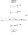
- step 101 the step response of the controlled object is observed.
- Duty ratio signal D1 D0 + ⁇ D (D0 is a present duty ratio, and ⁇ D is a duty ratio by which the open of ISC valve can be increased by ⁇ ) is outputted so that the open of SC valve can be increased by a predetermined open ⁇ , and the behavior of the rotating speed is measured at that time.
- the behavior of the rotating speed is as follows: when a signal of duty ratio D1 which increases the open of ISC valve by predetermined open ⁇ , is outputted, rotating speed Ne starts to increase being delayed by dead time L.
- step 102 the model is separated.
- the dynamic model of the control system is separated into a portion of dead time L and a portion after that.
- step 103 identification of model is conducted with regard to the portion of dead time L as the first dynamic model.
- transfer function G( s ) can be given as follows, and the degree of which is infinite.
- transfer function G a1 (z) in the case where dead time L is identified by a discrete system can be expressed as follows.
- G a1 (z) 1/z N
- L 240 msec
- G a1 (z) 1/z2 (1) Accordingly, the transfer function of the first dynamic model becomes simple in the discrete system as shown by the equation (1).
- step 104 model identification of the portion after dead time L is conducted as the second dynamic model.
- Constants a1, a2, b1, b2 of transfer function G a2 (z) can be experimentally found by means of the method of least square.
- Ne(z) is a function of the rotating speed which is a control output, and u(z) is a function of the duty ratio of the pulse signal which is a control input.
- the equation (3) is arranged with regard to Ne(z) as follows.
- Ne(z) (a1z ⁇ 1+a2z ⁇ 2) ⁇ Ne(z)+(b1z ⁇ 3+b2z ⁇ 4) ⁇ u(z) 3 ⁇ '
- z ⁇ 1 expresses a time delay operator.
- an estimated rotating speed Ne(i) can be estimated by the following equation according to the equation (3)'.
- Ne(i) a1 ⁇ Ne(i-1)+a2 ⁇ Ne(i-2)+b1 ⁇ u(i-3)+b2 ⁇ u(i-4) 4 ⁇
- estimated rotating speed Ne(i) a1 ⁇ Ne(i-1)+a2 ⁇ Ne(i-2)+b1 ⁇ u(i-3)+b2 ⁇ u(i-4)+d(i-1) 5 ⁇
- u shows a control input of ISC valve 44.
- u corresponds to the duty ratio of the pulse signal impressed upon the exciting coil 48
- i is a variable indicating the number of control conducted from the start of the first sampling.
- step 104 shown in Fig. 3 the dynamic model of the discrete system is directly found.
- the dynamic model of the continuous system is expressed as follows.
- G( s ) K ⁇ m 2/(S2+2T ⁇ m S+ ⁇ m 2)
- the raise of rotating speed is ⁇ Ne1
- the overshoot is ⁇ Ne2
- the time of occurrence of overshoot is t ov
- the variation of overshoot is ⁇ .
- Transfer function Gaz(z) of discrete system may be found by discretizing this transfer function G( s ) of the continuous system with sampling period ⁇ t.
- the following problems are caused: when the target rotating speed is changed stepwise (for example, when an air-conditioner is turned on and off, or when a transmission is shifted between N range and D range), the rotating speed converges to the target value without causing a deviation, however, when the target rotating speed varies ramp-wise (for example, in a warming-up operation, in a starting operation, and after racing), the engine speed is controlled while there is a constant amount of deviation. Therefore, the following are aimed at in this embodiment: when the target rotating speed is varied ramp-wise, calculation is carried out by two integrators; and when the target rotating speed is varied stepwise, or not varied, calculation is carried out by one integrator.
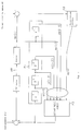
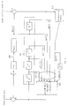
- Fig. 5 and Fig. 6 are block diagrams of the idling engine speed control system which is modeled in the aforementioned manner.
- the Z ⁇ 1 transformation is used in order to introduce control value u(i-1) from u(i). This corresponds to a process in which the past control value u(i-1) is stored in RAM 53 and read out in the next control so that is can be used.
- block P1 which is enclosed by a one-dotted line represents a portion to determine state variable X(i) under the condition that the rotating speed is fed back to the target rotating speed.
- Block P2 represents a portion (an accumulated portion) in which the aforementioned integral term u I (i) is found.
- Block P3 represents a portion in which the present control value u(i) is calculated from state variable X(i) determined in block P1, and from the integral term u I (i) found in block P2.
- the most optimum feedback gain K and integral constants Ka and Kb can be determined by the following technique.
- the most optimum feedback gain K and integral constants Ka and Kb are determined so that the following evaluation function can become minimum.
- Evaluation function J is intended to make the deviation of idling rotating speed Ne(i) as a control output from target rotating speed NF to be minimum while the control value u(i) of ISC valve 44 is being restricted. Weighting of restriction with regard to the control value u(i) can be changed according to parameters Q and R of weighting. Consequently, the most optimum feedback gain
- K [K1 K2 K3 K4 K5] and integral constants Ka and Kb may be determined in such a manner that: the values of weighting parameters Q and R are variously changed and simulation is repeatedly conducted until the most optimum control characteristic can be obtained.
- a load variation can be considered to be a variation factor.
- Concerning the most optimum feedback gains K, Ka and Kb, a plurality of them may be previously provided in such a manner that: for example, one is provided for a light load change, and the other is provided for a heavy load change; and the most optimum feedback gains are changed over according to the state of load variation.
- the feed back processing is conducted in this embodiment using the equations (8) and (9) or the equations (8)' and (9)'.
- the processing to prepare for the following feed back processing is executed in an open state at each computing timing to determine the control value.
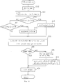
- the flow chart shown in Fig. 7 is a control program of ISC valve 44 which is conducted in the manner of interruption at each predetermined time (for example, 100msec) under the condition that an IG switch not shown in the drawing is closed.
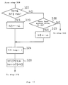
- step 302 When the interruption processing is started, it is judged in step 302 whether 3sec has passed after the start of the engine 10 or not.
- the object of the aforementioned judgment is to start the control from when the engine condition has become stable, getting out of an unstable condition of engine start. For example, the completion of an engine start operation is judged when rotating speed Ne of the engine 10 has exceeded 500rpm.
- step 302 When it is judged in step 302 that 3sec have passed after engine start, the process advances to step 304, and it is judged whether the throttle valve 31 is completely closed and the idle switch is turned on (LL : ON) or not.
- step 304 When it is judged in step 304 that LL : ON, the process advances to step 306, and it is judged whether a warm-up operation has been completed or not. When the warm-up operation has been completed, the process advances to step 308.
- step 308 it is judged whether a flag (an F/B flag) which is set to 1 when feed back (F/B) processing is carried out, is 1 or not.
- F/B flag 1
- the process advances to step 310.
- step 310 it is judged whether a target value raise NFOPEN which is set right after the state has been changed from an open state to a feed back processing executing state, is not more than 5rpm or not.
- NFOPEN ⁇ 5rpm the raise NFOPEN is made 0 in step 312, and then the process advances to step 314.
- NFOPEN ⁇ 5rpm it is judged in step 316 whether 1sec has passed or not after the F/B processing has been started. When 1sec has not passed yet, the process advances to step 314.
- the raise NFOPEN is corrected to a value smaller by 5rpm (NFOPEN ⁇ NFOPEN - 5rpm), and then the process advances to step 314.
- the aforementioned raise NFOPEN is added to a reference rotaitng speed NFB (for example, 700rpm) so that a target rotating speed NF is determined.
- step 320 an F/B processing which will be described later, is carried out corresponding to the target rotating speed NF determined in the aforementioned step 314.
- NA for example, 200rpm
- step 324 When Nen ⁇ NFB + NA, the process advances to step 324.
- step 326 it is judged whether 3sec have passed after LL : ON, or not. When 3sec have passed, the process advances to step 324.
- step 324 1 is set to the F/B flag, and then the process advances to step 328.
- step 328 the raise NFOPEN is found by subtracting the reference rotating speed NFB from the latest rotating speed Nen, and then the process advances to the aforementioned step 310. Accordingly, the rotating speed at the time when it is judged that F/B processing is started, is set to the initial value of the target rotating speed NF at the time of the start of F/B processing, by the processing of step 328.
- step 330 The process advances to step 330 in the following cases: in step 302, 3sec have not passed after the start; in step 304, LL : OFF; in srep 306, warming-up has not been completed; and in step 326, 3sec have not passed after LL: ON.
- step 330 the F/B flag is set to 0, and in step 332, an open processing which will be described later is carried out.
- step 320 or step 332 After the processing in step 320 or step 332 has been completed, storing processing to prepare for the following feed back processing, which will be described later, is carried out, and the control program is once completed, and then another engine control program is started.
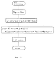
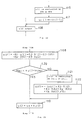
- the flow chart in Fig. 8 shows a case in which the disturbance and target rotating speed are constant in the F/B processing in step 320, and the processing according to the aforementioned equations (8) and (9) is carried out. Specifically, the latest rotating speed Nen is substituted into Ne(i) in step 402, and then the operation of the aforementioned equation (9) is carried out in step 404 so that u1(i) is found, and the operation of the equation (8) is carried out in step 406 so that the present control value u(i) is found. Then, a control signal of the duty ratio according to the present control value u(i) which has been found in the manner described above, is outputted from an output port 58 to ISC valve 44.
- the latest rotating speed Nen is set to Ne(i) for calculation.
- the deviation of Ne(i) from the target rotating speed NF is added to an integral term u1(i-1) which was found by the previous processing and stored in RAM53 so that the present u I (i) can be determined.
- the present state variable [Ne(i) Ne(i-1) u(i-1) u(i-2) u(i-3)] is determined from Ne(i) and the previous state variables Ne(i-1), u(i-1), u(i-2), u(i-3) which are stored in RAM53 being prepared for the present F/B processing.
- the present state variable and the most optimum feed back gain are calculated by means of a matrix calculation, and further Ka ⁇ u I (i) is added so that the present control value u(i) is determined.
- Fig. 9 is a flow chart showing an open processing of step 332.
- the present control value u(i) is set to a predetermined value u0 in step 502.
- the predetermined value u0 may be an arbitrary constant value as a duty ratio such as 100%, 0% and 50%, and it may be a value which can be determined in accordance with a detected parameter such as cooling water temperature Thw.
- step 504 the latest rotating speed Nen is substituted into Ne(i).
- step 506 the control value u(i) which has been set in the present time according to the equation (8), and the integral term u I (i) which agrees with the present state variable, are reversely calculated according to: Ne(i) which has been set in step 504; Ne(i-1), u(i-1), u(i-2), and u(i-3) which are stored in RAM53; and the present control value u(i) which has been set in step 502.
- the state variable at the open processing can be expressed by [Ne(i) Ne(i-1) u(i-1) u(i-2) u(i-3)] using Ne(i) which has been set in step 540 and Ne(i-1), u(i-1), u(i-2), u(i-3) which are sotered in RAM 53.
- step 508 a control signal of a duty ratio is outputted to ISC valve 44 from the output port 58 in accordance with the present control value u(i) which has been set in step 502.
- step 602 Ne(i), u(i-2), u(i-1) in the state variable which has been set either in step 320 (F/B processing) conducted right before or step 332 (open processing), are respectively substituted into Ne(i-1), u(i-3), u(i-2). Further, the present control values u(i) and uI(i) which have been determined in the aforementioned step 320 or step 332, are respectively substituted into u(i-1) and u1(i-1).
- step 604 Ne(i-1), u(i-3), u(i-2), u(i-1), u I (i-1) which have been determined in the aforementioned step 602, are stored in RAM 53.
- the state variable which is stored preparing for a reverse calculation of u(i) in the following F/B processing and open processing is renewed and stored, using Ne(i), u(i-2), u(i-1) which were utilized in steps 320, 332, and the control value u(i) which was determined in those steps.
- the value of u I (i) which was determined in step 320 (F/B processing) is stored, preparing for the following F/B processing.
- u I (i) calculated in step 332 (open processing) is also stored as an initial value which is used when u I (i) is calculated by the equation (9).
- u I (i) is stored after u I (i) has been changed into a form which is used for the following processing of calculation timing (step 602).
- the state variable stored in RAM 53 is renewed according to the rotating speed in the open state and the control value of ISC valve 44.
- the initial value of u I is calculated from the state variable and the control value at the time when the open processing is carried out, preparing for the following F/B processing, so that the state variable used for F/B processing when the state is changed from the open state to the F/B state, and the initial value of u I express the state of the system which controls the idling speed in the open state immediately before. Consequently, the variation of the rotating speed right after the state has been changed to the F/B state can be made very smooth. Since the most optimum state variable can be determined right after F/B control has started, the rotating speed can be quickly converged to the target rotating speed.
- the initial value of the target rotating speed NF at the time when the state has been changed from the open state to the F/B state so that the F/B processing is started is made equal to the actual rotating speed Ne at the time when it has been judged that the F/B processing is started.
- the target rotating speed is determined at the time of F/B processing start without any relation with the actual rotating speed
- a deviation is caused between the target rotating speed and the actual rotating speed at the start of the F/B processing, and in some cases, the actual rotating speed is higher than the target rotating speed by 400 - 500 rpm.
- the initial value of the target rotating speed is set in the manner described above at the start of F/B control operation, and the aforementioned problems can be solved.
- the raise NFOPEN at the start of F/B control is set so that it can be the difference value between the actual rotaing speed Nen and the reference rotating speed NFB, and this raise NFOPEN is held for 1 second after F/B.
- the slowdown of rotating speed can be restricted, and a sharp decrease in the rotating speed can be prevented.
- the raise NFOPEN is reduced to zero by a predetermined value after 1 sec has passed after the start of F/B, so that the actual rotating speed is smoothly lowered to the reference rotating speed NFB following the decrease in the target rotating speed NF.
- the rotating speed is very smoothly changed from the open state to the F/B state, so that a very stable idling condition can be obtained and drivability can be remarkably improved.
- the state variable and integral term are stored in the form corresponding to the next processing.
- the state variable and integral term are stored in the forms which have been used in the calculation processing of steps 320 and 332; and when the next processing is conducted in steps 320 and 332, the state variable is changed to a value corresponding to the calculation of the next processing.
- the F/B processing is conducted as follows: the previous state variables Ne(i), u(i-2), u(i-1), u(i) which are sotred in step 702, are respectively substituted into Ne(i-1), u(i-3), u(i-2), u(i-1); the previous integral term u I (i) is substituted into u I (i-1); and further the latest rotating speed Nen is substituted into Ne(i).
- the present state variable [Ne(i) Ne(i-1) u(i-1) u(i-2) u(i-3)] can be set.
- steps 704, 706, 708, the same processing as that of steps 404, 406, 408 is conducted.
- the open processing is conducted as follows: the previous state variables Ne(i), u(i-2), u(i-1), u(i) which are stored in step 802, are respectively substituted into Ne(i-1), u(i-3), u(i-2), u(i-1); and the latest rotating speed Nen is substituted into Ne(i).
- the present state variable [Ne(i) Ne(i-1) u(i-1) u(i-2) u(i-3)] can be set.
- the same processing as that in steps 502, 506, 508 in Fig. 9 is conducted in steps 804, 806, 808.
- the state variables Ne(i), u(i-2), u(i-1), u(i) and u I (i) which are obtained by the processing in step 902 shown in Fig. 14 and Fig. 15, are stored in RAM 53 in order to prepare for the next processing.
- the rotating speed at the time when it is judged that the F/B processing is started is used for the initial value of the target rotating speed in the F/B processing when the state has been changed from an open state to an F/B state.
- the value obtained by adding a predetermied value to the rotating speed at the time when it is judged that the F/B processing is started, or the value obtained by subtracting may be used for the initial value.
- + ⁇ : for example, + 50 rpm
- step 325 When the process advances to step 325 under the condition that LL : ON, not under the condition that Nen ⁇ NFB + NA, - ⁇ is set to the correction value NB, and then the process advances to step 324.
- the calculation result of Nen - NFB + NB is substituted into the raise NFOPEN in step 328, and then the process advances to step 310.
- the correction value NB is added so that the raise NFOPEN can be increased.
- the target rotating speed NF at the time of F/B start is set higher than the actual rotating speed at the time when it is judged that the F/B starts, by the correction value NB, so that this case is superior to the aforementioned embodiment in terms of restricting the slowdown speed.
- the initial value of the target rotating speed NF is made small in such a manner that the raise NFOPEN is made small by the correction value NB, when F/B processing starts after 3 sec have passed after LL : ON. Accordingly, the rotating speed of this case converges to the reference rotating speed NFB of a usual idling operation more quickly than the aforementioned embodiment.
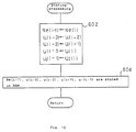
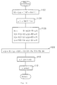
- step 1102 the deviation between the target rotating speed NF and the actual rotating speed Nen is added to the integral term u I0 which has been stored in the previous calculation timing so that the present integral term u I can be calculated.
- step 1104 the slip ⁇ N of the actual rotating speed Nen from the reference setting value Na (for example, 650 rpm) is calculated.
- step 1106 the state variables X10, X20, X30 which are sotred at the previous calculation timing, the increment ⁇ u0 of the control value u with regard to the reference setting value ua, and the slip ⁇ N which are found in step 1104, are weighted by the most optimum gains (b1, b2, b3, b4) and (q1, q2, q3, q4) and the present state variables X1, X2, X3, X4 are found.
- step 1108 the present uI which is found in step 1102, and the present state variables X1, X2, X3, X4 found in step 1106 are multiplied by the most optimum gains K1, K2, K3, K4, K5 so that the present increment ⁇ u is found.
- step 1110 the present control value u is determined from the reference setting value ua and the increment ⁇ u.
- step 1112 according to the determined present control value u, the control signal of the duty ratio is outputted from the output port 58 to ISC valve 44.
- step 1202 the present control value u is set to a predetermined value u0.
- This predetermined value u0 is the same as that in step 502 in the aforementioned embodiment.
- step 1204 the present increment ⁇ u is found from the control value u which is set in step 1202 and the reference setting value ua.
- step 1206 the slip ⁇ N of the actual rotating speed Nen from the reference setting value Na is calculated.
- step 1210 in the same manner as the aforementioned embodiment, u1 corresponding to the state is reversely calculated according to the present increment ⁇ u found in steps 1204, 1208 and the state variables X1, X2, X3, X4.
- step 1212 a control signal of the duty ratio according to the control value u which is set in step 1202, is outputted to ISC valve 44 from the output port 58.
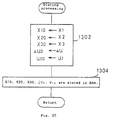
- step 1302 the values of X1, X2, X3, ⁇ u and u I of the present calulation timing which are determined when either the aforementioned F/B processing or the open processing is carried out in order to prepare for the next F/B processing, are defined as X10, X20, X30, ⁇ u0 and u I0 , and in step 1304, these X10, X20, X30, ⁇ u0 and u I0 are stored in RAM 53.
- the state variables X1, X2, X3, and X4 are also found corresponding to the state at the point of time, and the integral term u I is reversely calculated from the found state variables and the increment ⁇ u relating to the determined control value u.
- the previous state variables X10, X20, X30 which are stored at present for the next F/B processing, are replaced with the state variables X1, X2, X3 which have been found in the open state, in other words, the previous state variables are renewed and stored.
- Concerning u I instead of u I0 which is stored at the previous calculating timing, u I which has been found by a reverse calculation is stored.
- the completion of a warming-up operation is set as a condition of F/B.
- this condition may be eliminated, and the F/B processing may be conducted from the time in which a warming-up operation is being conducted.
- a mechanical air valve is installed in parallel with ISC valve 44 in order to supply air during the warming-up operation.
- the second embodiment will be explained which is suited for restricting the control value (the duty ratio) of ISC valve 44 to 20% - 80%, giving consideration to the adjustable range and linearity and of ISC valve 44.
- the flow chart shown in Fig. 21 can be obtained in such a manner that the processing of steps 410 - 413 is inserted into steps 404 - 406 in Fig. 8, and that the processing of steps of 414 - 416 is inserted into steps 406 - 408.
- step 402 the latest rotating speed Nen is substituted into Ne(i), and the calculation of the aforementioned equation (9) is carried out in step 404 so that u I (i) is found.
- step 410 it is judged whether u I (i) found in step 404 is larger than the value obtained by adding a predetermined value ⁇ to u I (i-1) determined at the previous calculation timing, or not.
- step 411 it is judged whether the integral term u I (i) found in step 404 is smaller than the value obtained by subtracting a predetermined value ⁇ from u I (i-1) determined at the previous timing, or not.
- u I (i) > u I (i-1) + ⁇ u I (i-1) + ⁇ is substituted into u I (i) in step 412.
- step 411 u I (i) ⁇ u I (i-1) - ⁇
- the value of u I (i-1) - ⁇ is substituted into u I (i) in step 413.
- the present u I (i) is maintained to be in the predetermined range in accordance with the previous u I (i-1).
- the present control value u I (i) is calculated according to the equation (8).
- the values of Ne(i-1), u(i-1), u(i-2) and u(i-3) which are used to calculate the present control value u I (i), are stored by the storing processing of step 334 in Fig. 7, preparing for the feed back processing.
- the present state variable X [Ne(i) Ne(i-1) u(i-1) u(i-2) u(i-3)] T can be set by these Ne(i-1), u(i-1), u(i-2) and u(i-3), and Ne(i) which has been found in the present processing. That is, in step 406, the present control value u I (i) is determined in such a manner that: the present state variable X which has been set in the aforementioned manner, and the most optimum gain
- K [K1 K2 K3 K4 K5[ which has been determined previously, are calculated by means of the matrix calculation; and further the present u I (i) is added.
- step 414 it is judged whether the present control value u I (i) calculated in step 406 is in the predetermined upper and lower limit (20 - 80%) or not.
- step 415 when the present control value u I (i) exceeds the upper limit (80%), the present control value u I (i) is set to 80%, and when the present control value u I (i) is smaller than the lower limit (20%), the present control value u I (i) is set to 20%.
- step 416 u I (i) is reversely calculated so that the restricted control value u(i) and the state variable can be satisfied by the eighth equation corresponding to the restriction of the control value u(i).
- step 408 the control signal of the duty ratio according to the present control value u(i) which has been set in step 406 or step 415, is outputted from the output port 58 to ISC valve 44.
- the final control value u(i) is controlled into the predetermined range of the upper and lower limit in the feed back processing. While the control value u(i) is restricted, u I (i) is reversely calculated so that the restricted control value u(i) and the state variable can be satisfied by the equation (8).
- control value u(i) can be varied in the direction opposite to the restriction sensitively to the engine state, so that the valve 44 can be operated in a quick response. That is, the problem of response delay described in the aforementioned prior art can be sufficiently solved.
- the initial value u I (i) immediately after the state has been changed from the state in which the control value is restricted, into the state in which the control value is not restricted, is determined corresponding to the state variable of an engine just before its state is changed. Consequently, the value of u I can be smoothly changed when the state is changed in the aforementioned manner, so that the variation in rotating speed can be restricted when the state is changed.
- step 415 while the present control value u(i) is restricted in step 415, the value of u I (i) is reversely calculated in step 415. However, while the present control value u(i) is restricted in step 415 as shown in Fig. 22, the present u I (i) may be held to be u I (i-1) of the previous calculation timing.
- FIG. 23 a flow chart shown in Fig. 23, the embodiment shown in Fig. 18 will be explained in the case where the present control value u(i) is restricted in the manner described above.
- the flow chart shown in Fig. 23 is composed in such a manner that: steps 1120 - 1122 are inserted between step 1108 and step 1110 in the flow chart of Fig. 18.
- step 1120 it is judged whether the present increment ⁇ u(i) calculated in the manner described above in step 1108 is within a predetermined upper and lower limit ( ⁇ u min - ⁇ u max ) or not.
- step 1121 when the present increment ⁇ u(i) is out of the range and exceeds the upper limit ⁇ u max , the present increment ⁇ u(i) is set to the upper limit ⁇ u max .
- the present increment ⁇ u(i) is smaller than the lower limit ⁇ u min , the present increment ⁇ u(i) is set to the lower limit ⁇ u min .
- u I (i) is reversely calculated according to the following equation.
- u I (i) -( ⁇ u(i) + K2 ⁇ X1(i) + K3 ⁇ X2(i) + K4 ⁇ X3(i) + K5 ⁇ X4(i))/K1
- step 1110 the present control value u is determined according to the present increment ⁇ u(i) which has been set in step 1108 or step 1121, and according to the reference setting value ua.
- the flow chart of Fig. 24 is a control program of a step type of control valve.
- the processing when the processing is started at each predetermined period of time (for example, each 100msec), it is judged in step 2001 whether the operating condition of the engine 10 agrees with the condition to carry out the feed back control of idling speed.
- the feed back conditions are as follows: a predetermined period of time (for example, 3 sec) has passed after the start of the engine; the throttle valve 31 is completely closed; and a warming-up operation has been completed. When all the conditions are satisfied, the process advances to step 2004, and feed back control is conducted so that the engine speed can become the target speed.
- step 2001 when it is judged in step 2001 that the feed back conditions are not satisfied, the open processing after step 2002 is conducted.
- the present control value u(i) is set to a predetermined value u0 in a step.
- This predetermined value u0 may be an arbitrary constant value such as 100% and 50% as a duty ratio, or it may be a value which can be determined according to a detection parameter such as cooling water temperature Thw.
- detected rotating speed Nen is substituted into Ne(i) in step 2003, and then the process advances to step 2016.
- step 2004 the target rotating speed NF is determined according to cooling water temperature Thw, intake temperature Tam, the ON-OFF state of an air-conditioner, and the range position of an automatic transmission.
- step 2005 the latest detected rotating speed Nen is substituted into Ne.
- step 2006 the integral value u I (i) is renewed according to the ninth equation on the basis of the deviation between the aforementioned target rotating speed determined in step 2004 and Ne(i) determined in step 2004.
- the present control value u(i) is calculated according to the equation (8).
- the values of Ne(i-1), u(i-1), u(i-2) and u(i-3) which are used to calculate the present control value u(i), are stored in step 2022, preparing for the feed back processing.
- the present state variable X [Ne(i) Ne(i-1) u(i-1) u(i-2) u(i-3)] T can be set by these Ne(i-1), u(i-1), u(i-2) and u(i-3), and Ne(i) which has been found in the present processing.
- step 2007, the present control value uI(i) is determined in such a manner that: the present state variable X which has been set in the aforementioned way and the most optimum gain
- K [K1 K2 K3 K4 K5] which has been determined previously are calculated by means of the matrix calculation; and further the present u I (i) is added.
- step 2008 it is judged whether the present control value u(i) calculated in step 2007 is in the predetermined upper and lower limit (20 - 80%) or not.
- step 2009 when the present control value u(i) exceeds the upper limit (80%), the present control value u(i) is set to 80%, and when the present control value u I (i) is smaller than the lower limit (20%), the present control value u(i) is set to 20%.
- step 2009 After the restriction has been conducted on the present control value u(i) in step 2009, the process advances to step 2016.
- step 2010 it is judged whether the absolute value of the deviation of the detected rotating speed Ne(i) from the target rotating speed NF is not more than a predetermined value (for example, 25 rpm in this embodiment), or not.
- a predetermined value for example, 25 rpm in this embodiment
- flag FSTA 1 or not.
- Flag FSTA is set when the rotating speed is close to the target rotating speed in a steady condition.
- step 2011 When flag FSTA is not set in step 2011, counter C is counted up in step 2012 (C ⁇ C+1). Counter C is used to measure the time which has passed from when the absolute value of the aforementioned deviation became not more than the predetermined value. In step 2013, it is judged whether the value counted by counter C is not less than a predetermined value (for example, in this embodiment, 50) or not, that is, whether a predetermined period of time (for example, in this embodiment, 5 seconds) has passed or not after the absolute value of the aforementioned deviation became not more than a predetermined value. When the predetermined period of time has not passed yet, the process advances to step 2019.
- a predetermined value for example, in this embodiment, 50
- a predetermined period of time for example, in this embodiment, 5 seconds
- step 2104 flag FSTA is set in step 2104 (FSTA ⁇ 1) and the process advances to step 2015.
- step 2016, u I (i) is reversely calculated according to the following equation so that the present control value u(i) and state variable X can satisfy the eighth equation, when the present control value u(i) is restricted in step 2009, when the present control control value u(i) is set to the predetermined value u(i) in an open processing in step 2002, and when the present control value u(i) is set to the steady condition control value uAV(i) in a steady condition in step 2015, that is, when the present control value u(i) is set to a value having no relation with state variable X.
- step 202 the control signal of the duty ratio corresponding to the present control value u(i) which has been set in either step 2002, step 2007, step 2009 or step 2015, is outputted from the output port 58 to a step motor type of control valve.
- Ne(i), u(i-2), u(i-1), u(i), u I (i) and uAV(i) which have been set in the manner described above, are respectively substituted into Ne(i-1), u(i-3), u(i-2), u(i-1), u I (i-1) and uAV(i).
- Ne(i-1), u(i-3), u(i-2), u(i-1), u I (i-1) and uAV(i-1) which have been set in step 2021, are stored in RAM 53, and then the processing is completed.
- step 2019, the steady state control value uAV(i) is set by processing the present control value u(i).
- the average of the control value u(i) may be used for the steady state control value uAV(i) as shown by the following equation.
- uAV(i) ⁇ u(i) + u(i-1) + u(i-2) + u(i-3) ⁇ /4
- the present control value u(i) is set to the steady state control value uAV(i).
- this steady state control value uAV(i) is not renewed. Consequently, the variation of the operation of a step motor type of control valve can be inhibited, so that the durability can be improved.
- the state variable can be always set even in an open loop state. Therefore, even in the case where the state is changed from a state in which the present control value is set without any relation to the present state variable, into a state in which the present control value is set in accordance with the present dtate variable, the present state variable has been already set, so that the adjusting means can be operated in a quick response and the convergence to the target rotating speed can be improved.
- control value (the duty ratio) with regard to ISC valve 44 is limited by the upper and lower limit of 0% - 100% in accordance with the adjustable range of ISC valve 44. Further, state variables X1(i) - X5(i) and the integral term u I (i) are also limited by a predetermined upper and lower limit.
- feedforward control is also conducted in accordance with the state of load given to the engine 10 by the aforementioned air conditioner and transmission, and in accordance with the state of rotating speed Ne obtained from the rotating speed sensor 30.
- feedforward processing is carried out to the cases in which the upper and lower limit are respectively set to the control value, the state variable and the integral term.
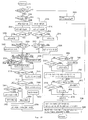
- a flow chart in Fig. 25 is a control program of ISC 44, and this control program is carried out at each predetermined time (for example, at each 100msec) in the manner of interruption under the condition that an IG switch not shown in the drawing is closed.
- step 3302 When interruption processing is started, it is judged in step 3302 whether the operating condition of the engine 10 satisfies the conditions to carry out feedback control of the idling speed, or not.
- the feedback conditions are as follows: a predetermined period of time (for example, 3 sec) has passed after the start of the engine; the throttle valve 31 has been completely closed; and a warming-up operation has been finished. When all the conditions are satisfied, the process advances to step 3304.
- step 3304 it is judged whether a neutral switch 64 is turned on or not, that is, the automatic transmission is in the neutral range (the neutral range or parking range) or not.
- the process advances to step 3306.
- the automatic transmission is in a drive range (one of the low, second, drive and reverse range) and the switch 64 is turned off, the process advances to step 3308.
- step 3306 reference rotating speed NFB is set to 700 rpm, and in the next step 3310, the rotation of 5 rpm is added to the previously set target rotating speed NF.
- step 3312 target rotating speed NF and reference rotating speed NFB are compared, and when NF > NFB, reference rotating speed NFB is set to be used for target rotating speed NF.
- step 3308 reference rotating speed NFB is set to 600 rpm, and in the next step 3316, the rotation of 5 rpm is subtracted from target rotating speed NF.
- step 3318 target rotating speed NF found in step 3316 and reference rotating speed NFB are compared, and when NF ⁇ NFB, reference rotating speed NFB is set as target rotating speed NF in step 3320.
- the basic level of the target rotating speed is changed over according to the state of the automatic transmission whether it is in the neutral range or the drive range.
- Target rotating speed is not set according to the changed-over range right after the automatic transmission has been changed over between the neutral and drive range.
- the rotating speed is gradually changed to the target rotating speed as the time passes after the change-over.
- target rotating speed NF is gradually reduced from 700 rpm to 600 rpm at a ratio of 5 rpm per 100 msec.
- target rotating speed NF is increased from 600 rpm to 700 rpm at a ratio of 5 rpm per 100 msec.
- step 3322 and step 3324 the position of the neutral switch 64 is checked, and when it is judged that the present state of the neutral switch is different from the previous state so that the range of the automatic transmission has been changed over, the integral term u I (i-1) stored in the aforementioned RAM is corrected once in the manner of feedforward in steps 3326 and 3328.
- the automatic transmission is changed over from the drive range to the neutral range in step 3326 so that the load given to the engine 10 is decreased. Therefore, the integral term u I (i-1) is once decrease-corrected by ⁇ 1 after change-over.
- step 3328 the load given to the engine 10 is increased. Therefore, the integral term u I (i-1) is once increase-corrected by ⁇ 1 after change-over.
- steps 3338 and 3340 it is judged whether the variation in rotating speed which can be found by subtracting detected rotating speed Nen at the present proceeing timing from detected rotating speed Neo at the previous processing timing, especially the decrease, is larger than a predetermined value A or not.
- the integral term u I (i-1) is increase-corrected by ⁇ 3.
- steps 3342 and 3344 it is judged whether detected rotating speed Nen is in the range of upper limit Ne max (for example, 1600 rpm) and and lower limnit Ne min (for example, 400 rpm).
- step 3350 the aforementioned lower limit Nemin is substituted into Ne(i) which will be used in a calculation which will be described later.
- step 3354 detected rotating speed Nen is substituted into Ne(i). That is, in steps 3350, 3352 and 3354, Ne(i) is limited into the predetermined upper and lower range (Ne min - Ne max ).
- the present integral term u I (i) is calculated according to the aforementioned ninth equation, using NF, Ne(i) and u I (i-1) which are determined or corrected by the aforementioned processing. Then in the next steps 3358, 3360, it is judged whether the calculated integral term u I (i) is in a predetermined upper and lower limit (0% - 100%). When the integral term u I (i) exceeds the upper limit (100%), the integral term u(i) is set to 100% in step 3362, and when the integral term u I (i) is lower than the lower limit (0%), the integral term u I (i) is set to 0% in step 3364. The upper and lower limit of this integral term u I (i) are set to a range in which the control value u(i) found by the aforementioned eighth equation can actually operate ISC valve 44.
- the present control value u(i) is found according to the eighth equation.
- the values of Ne(i-1), u(i-1), u(i-2) and u(i-3) which are utilized for calculating the present control value u(i), are stored in the previous processing, being prepared for this feedback processing.
- the present state variable X [Ne(i) Ne(i-1) u(i-1) u(i-2) u(i-3)] T can be set according to these Ne(i-1), u(i-1), u(i-2), u(i-3), and Ne(i) which is found by the present processing.
- the values of Ne(i) and Ne(i-1) in the aforementioned state variable X are limited to be in a predetermined upper and lower limit by the aforementioned processing of steps 3342, 3344, 3350, 3352 and 3354.
- step 3368 and 3370 it is judged whether the present control value u(i) calculated in step 3366 is in a predetermined upper and lower limit (0% - 100%) or not.
- the present control value u(i) is set to 100% in step 3372, and when it is lower than the lower limit (0%), the present control value u(i) is set to 0%.
- the upper and lower limit of the control value u(i) is set in such a manner that it is in a range within which ISC valve 44 can be actually operated.
- u(i-1), u(i-2) and u(i-3) at the aforementioned state variable X are also limited within the upper and lower limit (0% - 100%).
- step 3376 a control signal of the duty ratio according to the present control value u(i) determined in the manner described above, is outputted from the output port 58 to ISC valve 44.
- step 3302 When it is judged in the aforementioned step 3302 that the feedback conditions are not satisfied, the process advances to the open processing in step 390.
- Fig. 4 shows the content of the open processing.
- the present control value u(i) is set to the predetermined value u0 in step 402.
- This predetermined value u0 may be an arbitrary value such as 100%, 0% and 50% as a duty ratio, or it may be a value determined according to a detected parameter such as a cooling water temperature Thw.
- steps 404, 406, 408, 410 and 412 upper limit Ne max and lower limit Ne min at detected rotating speed Nen and idling rotating speed are compared in the same manner as the aforementioned steps 342, 344, 350 and 354.
- Ne min ⁇ Nen ⁇ Ne max Nen is substituted into Ne(i).
- the control value u(i) which has been set this time and the integral term u I (i) which agrees with the present state variable are reversely calculated according to the eighth equation from; Ne(i) which have been set in steps 408, 410 and 412; Ne(i-1), u(i-1), u(i-2) and u(i-3) which have been stored in RAM 53; and the present control value u(i) which has been set in step 402.
- the state variable in this open processing can be expressed by [Ne(i) Na(i-1) u(i-1) u(i-2) u(i-3)] from; Ne(i) which has been set in steps 3408, 3410 and 3412; and Ne(i-1), u(i-1), u(i-2) and u(i-3) which are stored in RAM 53.
- step 3378 the values of Ne(i), u(i-2) and u(i-1) in the state variable which has been set either in the feedback processing of steps 3304 - 3374 or in the open processing of step 3390, are respectively substituted into Ne(i-1), u(i-3) and u(i-2), and then the present control value u(i) which has been determined in the aforementioned feedback processing or open processing, and u I (i), are respectively substituted into u(i-1) and u I (i-1).
- step 3380 the values of Ne(i-1), u(i-3), u(i-2), u(i-1) and u I (i-1) which have been determined in the aforementioned step 3378 arestored in RAM 53.
- the state variable which is stored, being prepared for the next feedback processing and the reverse calculation processing of the integral term in the next open processing is renewed and stored, utilizing Ne(i), u(i-2), and u(i-1) used in the feedback processing and open processing, and utilizing the control value u(i) determined in each processing.
- the integral term u I (i) determined in the feedback processing is also stored, being prepared for the next feedback processing.
- the integral term u I (i) calculated in the open processing is also stored as the initial value used when the integral term is calculated according to the equation (9) in the next feedback processing.
- the values are stored after they have been changed into the form which can be used in the processing of the next calculation timing (step 3378).
- the stored integral term u I (i-1) is corrected only once in the manner of feedforward corresponding to the change of load given to the engine 10 which is caused when the air-conditioner or automatic transmission is operated. Therefore, the integral term u I (i) is not influenced by the aforementioned feedback and feedforward processing and can be fully changed in the range of the upper and lower limit. Accordingly, the following problem caused in conventional technique can be solved: although the detected rotating speed is higher than the target rotating speed, the control value u I (i) can not be reduced so that ISC valve 44 can not be closed.
- the integral term u I (i-1) is immediately corrected in the manner of feedforward, so that engine stall can be sufficiently prevented even when the load given to the engine 10 is suddenly increased by a disturbance caused by some reasons. Furthermore, when the idling engine speed has reached a predetermined upper and lower limit, the integral term u I (i-1) is corrected in the manner of feedforward so that the idling engine speed can be settled in the range of the upper and lower limit.
- the open of ISC valve 44 is increased or decreased corresponding to the aforementioned feedforward correction, so that the idling engine speed can be immediately returned to the target rotating speed side.
- feedback processing is simultaneously conducted, so that the idling rotating speed can be smoothly returned to the target rotating speed.
- the target rotating speed is suddenly changed in the aforementioned idling engine speed control in which recent control having excellent response property is utilized, an extreme overshoot and undershoot are caused, so that the engine speed is varied sharply.
- the target rotating speed is not changed over immediately after the automatic transmission has been changed over between the neutral range and the drive range, but the target rotating speed is gradually changed over to the value corresponding to the directed range as the time passes. Accordingly, the aforementioned extreme variation in engine speed is not caused by the overshoot and undershoot.
- the target rotating speed is lowered in order to prevent a creep.
- the control is conducted in the manner described before, so that the present invention is especially effective in the case where the target rotating speed must be lowered although the load is increased, and this technique is essential in the idling engine speed control in which recent control having excellent response property is utilized.
- the present integral term u I (i) is obtained in such a manner that: the stored integral term u I (i-1) is corrected in the manner of feedforward; accumulation processing is conducted on the corrected integral term u I (i-1) in accordance with the difference between NF and Ne(i).
- the integral term corrected in the manner of feedforward may be used for the present integral term u I (i), and accumulation processing may not be conducted on the aforementioned integral term corrected in the manner of feedforward in accordance with the difference between NF and Ne(i).
- step 3342 - step 3354 the upper and lower limit with regard to detected rotating speed Nen for correcting the integral term u I (i-1) in the manner of feedforward, and the upper and lower limit of Ne(i) used for a state variable, are set to the same values of Ne max and Ne min .
- the upper and lower limit may be respectively set to different values.
- the stored integral term u I (i-1) is directly incresed or decreased by predetermined values ( ⁇ 1, ⁇ 2, ⁇ 3, ⁇ 4, ⁇ 1, ⁇ 2, and ⁇ 4) so that the integral term u I (i) is corrected.
- the integral term u I (i) may be corrected in such a manner that: the target rotating speed NF which has been set at the time is adjusted corresponding to the aforementioned variation, and a temporary target rotating speed NF' is made.
- step 3365 when the process advances to step 3365 through one of step 3322 and step 3324, step 3330, step 3332, step 3338, step 3342, step 3344, and step 3354 without causing the aforementioned changes, the same processing as described above, is carried out.
- the temporary target rotating speed NF' is set in one of step 3326', step 3328', step 3334', step 3336', step 3340', step 3346', and step 3348', and then the present integral term u I (i) can be determined in step 3365'.
- step 3365' the setting process of Ne(i) is previously conducted, that is, Ne(i) is previously set by the same processing as that in steps 3342, 3344, 3350, 3352 and 3354.
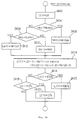
- steps 3302 - 3348 are the same as those shown in Fig. 3.
- the integral term u I (i-1) which is stored at the previous calculation timing in step 3602 and corrected in the aforementioned processing of steps 3304 - 3348 when necessary, is found, and the integral term u I (i) is found according to the deviation of detected rotating speed Nen from target rotating speed NF.
- step 3604 it is judged whether the found integral term u I (i) is in the upper and lower limit (-u a ⁇ 100 -u a ) or not.
- step 3608 slip ⁇ N of detected rotating speed from reference setting value Na (for example, 650 rpm) is calculated.
- state variables X1(i-1), X2(i-1), X3(i-1) which are stored in the previous calculation timing, increment ⁇ u(i-1) of the control value u(i) with regard to the reference setting value ua, which is also stored, and slip ⁇ N which is found in step 3608, are weighted and added so that state variables X1(i), X2(i), X3(i) and X4(i) are found.
- step 3612 and 3614 it is judged whether the values of state variables X1(i) - X4(i) which are found in step 3610 are in the range of a predetermined upper and lower limit or not. When the state variables are out of the range, they are restricted by the upper or lower limit.
- step 3616 the present integral term u I (i) which has been obtained through the processing of steps 3602 - 3606, and the present state variables X1(i), X2(i), X3(i) X4(i), are multiplied by the most optimum gains K1, K2, K3, K4, K5 and added so that the present integral value ⁇ u(i) is found.
- step 3618 the control value u(i) is found from the reference setting value ua and the increment ⁇ u(i).
- steps 3620 and 3622 it is judged whether the control value u(i) found in step 3618 is in the range of a predetermined upper and lower limit (0 - 100) or not. When the control value u(i) is out of the range, it is restricted by the upper limit (100) or the lower limit (0) so that the present control value u(i) is determined.
- step 642 a control signal of the duty ratio corresponding to the determined present control value u(i) is outputted from the output port 58 into ISC valve 44.
- the present control value u(i) is set to a predetermined value u0 in step 3624.
- This predetermined value u0 is the same as that in step 3402 in the aforementioned embodiment.
- the present increment ⁇ u(i) is found from the control value u(i) which has been set in step 3624 and the reference setting value ua.
- a slip ⁇ N is calculated which is a slip of detected rotating speed Nen from reference setting value Na.
- step 3630 state variables X1(i), X2(i), X3(i) and X4(i) in this open state are found by the same processing as that used in step 3610, preparing for the next feeback processing.
- steps 3632 and 3634 values X1(i) - X4(i) composing the state variable are restricted into the range of the upper and lower limit by the same processing as that in steps 3612 and 3614.
- step 3636 the integral term u I (i) is reversely calculated in the same manner as the aforementioned embodiment according to the present increment ⁇ u(i) and state variables X1(i), X2(i), X3(i) and X4(i) which have been found through the steps of the aforementioned open processing.
- steps 3638 and 3640 the integral term u I (i) which have been found in the same manner as steps 3604 and 3606, is restricted into the range of the upper and lower limit.
- step 3642 a control signal of the duty ratio corresponding to the control value u I (i) which has been set in step 3624, is outputted from the output port 58 into ISC valve 44.
- step 3644 being prepared for the next feedback processing, X1(i), X2(i), X3(i), ⁇ u(i) and u I (i) at the present calculation timing which have been determined through either the aforementioned feedback processing or the open processing, are respectively set to X1(i-1), X2(i-1), X3(i-1), ⁇ u(i-1) and u I (i-1).
- step 646 these X1(i-1), X2(i-1), X3(i-1), ⁇ u(i-1) and u I (i-1) are stored in RAM 53 so that the present calculation and cotrol processing is completed and other procssing is started.
- the calculation is performed at a constant period. However, the calculation may be carried out each time when a predetermined rotating angle is detected.
- target rotating speed NF is gradually changed by the processing of steps 3304 - 3320 shown in Fig. 25 when the range of the automatic transmission is changed over, so that while target rotating speed NF is being changed, detected rotating speed Nen differs from target rotating speed NF. Therefore, the processing of step 3356 in Fig. 25 is conducted in accordance with the following equation.
- U I (i) 2 ⁇ u-(i-1) - u-(i-2) + Ka ⁇ (NF - Ne(i))
- step 3378 the processing of u I (i-2) ⁇ u I (i-1) is added in step 3378, and u I (i-2) is also stored in step 3380.
- u I (i-2) is also stored in step 3380.
- the integral value which is calculated by the integral value calculating means is corrected in the manner of feedforward, before the integral value is restricted into a predetermined range in accordance with the sate change by the integral value restricting means, so that the integral value can be fully varied within the predetermined range, and even when a feedforward correction is conducted in accordance with a load disturbance, the control value can be also varied within the predetermined range.
- the following conventional problems can be solved: even when a detected rotating speed is higher than a target rotating speed and the final control value is made minimum, if a load disturbance is given and correction is conducted, the rotating speed can not become not more than a value which is larger than the lower limit of the final control value by a predetermined value; and the idle control valve is maintained open by a predetermined open value, so that the detected rotating speed can not be converged to the target rotating speed, and the rotating speed is maintained high. Accordingly, the present invention can provide an excellent effect that the detected rotating speed can be accurately converged to the target rotating speed.
Abstract
Description
- The present invention relates to a digital control unit, and more particularly relates to a unit to control an idling engine speed in such a manner that: consideration is given to the internal state of a system to control the idling speed of an internal combustion engine; the system is grasped as a dynamic system; and the idling engine speed is controlled corresponding to a control value which is found in accordance with a state variable which determines the internal state.
- Conventionally, this kind of idling speed control unit of an internal combustion engine has been disclosed, for example, in the official gazette of Japanese Patent Application Laid Open No. 145339-1984. In this official gazette is shown a composition characterized in that: when the engine condition is changed from the one in which the idling engine speed is not fed back, to the one in which the idling engine speed is fed back, the engine speed can be smoothly changed to a target value.
- However, in the composition shown in the aforementioned official gazette, when it has been judged that the feedback control of the engine speed is started, the initial values of the state variable used when the control value to control the engine speed is found, and the initial value of the integral term of the deviation between the detected engine speed and the target engine speed, are given in accordance with the engine speed detected when the throttle valve has been completely opened, and the engine speed detected when it has been judged that feedback control is started. Therefore, the initial value of the state variable and that of the integral term must be prepared corresponding to the engine speed detected when the throttle valve has been completely closed, and the engine speed detected when it has been judged that feedback control is started. Even when the initial values are finely set corresponding to the aforementioned engine speed, as the internal state of the system to control the idling speed of an internal combustion engine and the engine speed can not be determined definitely, it is not clear whether the given initial values are appropriate or not. Therefore, there is a possibility that the convergence to the target engine speed is deteriorated depending on a case.
- Accordingly, the present invention has been achieved to solve the aforementioned problems. It is a primary object of the present invention to provide a digital control unit characterized in that: the convergence to a target engine speed can be improved when the engine condition is changed from the one in which the aforementioned actuator is driven without any relation with the internal state of an internal combustion engine, to the one in which the aforementioned actuator is driven by the value which is set according to the internal state of the internal combustion engine.
- When a disturbance load such as a load of an air-conditioner is given to an engine, the transient response of the idling engine speed is conventionally improved by correcting a value computed by feedback control in accordance with the disturbance.
- In the case of an idling speed control unit of an internal combustion engine, consideration is given to the operable range of an actuator (for example, an idling speed control valve) to control the idling engine speed, and the finally outputted control value (the duty ratio of a duty signal to control a control solenoid) is generally controlled so that it can be within a predetermined upper and lower limit (0 - 100%). As shown in the official gazette of Japanese Patent Application Laid Open No. 43942-1984, the upper and lower limit are also set to the integral value and the state variable, in order to prevent the actuator from being affected when the control value found by the previous calculation timing used for determining the finally outputted control value, the state variable determined by the detected engine speed, and the integral value of the deviation between the target engine speed and the detected engine speed, become excessively high or low.
- Therefore, when the conventional composition in which the calculation value obtained by feedback control is corrected by the correction in accordance with a disturbance, is applied to the aforementioned apparatus in which the upper and lower limit are set to the final control value, the integral value, and the state variable, the following problems are caused: even when the detected engine speed is higher than the target engine speed and the final control value is made minimum, the correction is added as a load disturbance is given, so that the engine speed can not be reduced to not more than the value which is larger than the lower limit of the final control value by a predetermined value. In this case, the idle speed control valve is maintained in a condition in which it is opened by a predetermined open value. Therefore, the detected engine speed can not be converged to the target engine speed, so that there is a possibility that the engine speed is maintained high.
- Consequently, the second object of the present invention is to provide an improved digital control unit which is characterized in that: when the control value is corrected in the manner of feedforward, giving consideration to the influence caused by a load disturbance, the detected engine speed can be very precisely controlled to the target engine speed, without causing the aforementioned problems.
- The third object of the present invention is to provide a digital control unit characterized in that: a highly precise dynamic model of low degree is constructed, and very accurate control can be conducted according to the constructed dynamic model.
- In the present invention, even while the present control value is set without any relation to the present state variable, the state variable is always set.
- Accordingly, even when the engine condition is changed from the condition in which the present control value is set without any relation to the present state variable, to the condition in which the present control value is set according to the present state variable, the convergence to the target value can be greatly improved since the present state variable has already been set.
- In the present invention, when the change of load state is detected, the integral value is corrected in the manner of feedforward before the integral value is restricted within a predetermined range in accordance with the change of state, so that the integral value can be fully changed within the predetermined value, and the control value is also fully changed within a predetermined value even when a feedforward correction is conducted according to a load disturbance. Therefore, the conventional problems can be solved which are described as follows: even when the detected engine speed is higher than the target engine speed and the final control value is made minimum, the correction is added as a load disturbance is given, so that the engine speed can not be reduced to not more than the value which is larger than the lower limit of the final control value by a predetermined value; the idle speed control valve is maintained in a condition in which it is opened by a predetermined open; and therefore, the detected engine speed can not be converged to the target engine speed, so that there is a possibility that the engine speed is maintained high. Accordingly, the detected engine speed can be accurately converged to the target engine speed.
- In the composition of the present invention, when a dynamic model of the control system is constructed, consideration is given to dead time, and more particularly a portion of dead time and a portion after that are divided so that the dynamic model is identified with a discrete system. The entire dynamic model is previously constructed on the basis of the identified dynamic model. When the dynamic model is constructed giving consideration to dead time, a highly precise dynamic model can be obtained. In the present invention, on the basis of the previously constructed dynamic model, the state variable is determined according to the control input and output, and the control input is outputted according to the determined state variable, so that highly precise control can be realized with a simple structure (using a dynamic model of low degree).
- When the present invention is applied to the control of idling speed of an internal combustion engine, highly accurate idling engine speed control can be realized using a dynamic model of low degree, in other words, using a simple structure.
-
- Fig. 1 is a block diagram of the present invention;
- Fig. 2 is a schematic illustration showing an internal combustion engine to which the embodiment of the present invention is applied, and its peripheral equipments;
- Fig. 3 is a view explaining a modeled operation;
- Fig. 4 is a characteristic diagram of a rotating speed with regard to a control signal;
- Fig. 5 and Fig. 6 are block diagrams of a system to control an idling engine speed;
- Fig. 7 - Fig. 10 are flow charts of an ISC valve control program in the case where one integrator is provided;
- Fig. 11 - Fig. 13 are flow charts of an ISC valve control program in the case where two integrators are provided; and
- Fig. 14 - Fig. 28 are flow charts showing an essential content of other embodiments.
- An embodiment will be explained as follows. As shown in Fig. 1, the block of this embodiment is an idling speed control unit of an internal combustion engine, comprising: a rotating speed detecting means to detect the engine speed of an internal combustion engine; a rotating speed adjusting means to adjust the engine speed of the internal combustion engine; and a control means which calculates a control value to control the aforementioned rotating speed adjusting means at a predetermined cycle so that the detected rotating speed which has been detected by the aforementioned rotating speed detecting means, can coincide with a desirable target rotating speed, and which outputs a control signal according to the control value. The aforementioned control means is provided with: the first control value setting means which sets a state variable according to the aforementioned detected rotating speed, a state variable set by the previous operation timing, and the aforementioned control value corresponding to the aforementioned control signal outputted to the aforementioned rotating speed adjusting means, and which sets the present control value according to the aforementioned state variable; the second control value setting means which sets a state variable according to the aforementioned detected rotating speed, the state variable set by the previous operation timing, and the aforementioned control value corresponding to the aforementioned control signal outputted to the aforementioned rotating speed adjusting means, and which sets the present control value to a value having no relation with the state variable; and a selecting means which selects either the aforementioned first control value setting means or the aforementioned second control value setting means according to the state of the aforementioned internal combustion engine.
- Referring now to the drawings, an idling speed control unit will be explained to which the present invention is applied. Fig. 2 is a schematic illustration showing an
engine 10 in which the idling speed control are explained as follows, and its peripheral equipments are shown. As illustrated in the drawing, in this embodiment, the control of an ignition timing, a fuel injection and an idling speed of theengine 10 is conducted by anelectronic control unit 20. However, the control of an idling speed will be mainly explained here. Theengine 10 is installed in a vehicle. As illustrated in Fig. 2, theengine 10 is a spark-ignition engine. Suction air is sucked from the upstream to each cylinder through anair cleaner 21, anair flow meter 22, asuction pipe 23, asurge tank 24, and asuction manifold 25. On the other hand, fuel is fed with pressure from a fuel tank not shown in the drawing, and injected fromfuel injection valves suction manifold 25. Theengine 10 is provided with: adistributor 29 which distributes an electric signal of high voltage supplied from anignition circuit 27, toignition plugs speed sensor 30 which is provided in thedistributor 29 to detect rotating speed Ne of theengine 10; athrottle sensor 32 which detects opening TH of athrottle valve 31; a warming-up sensor 33 which detects cooling water temperature Thw of theengine 10; and asuction temperature sensor 34 which detects suction temperature Tam of theengine 10. The rotatingspeed sensor 30 is provided in such a manner that it is opposed to a ring gear which rotates synchronously with the crank shaft of theengine 10, and outputs a pulse signal proportionally to the engine speed in such a manner that 24 pulses are outputted while theengine 10 is rotated one revolution, that is, 720°CA. Thethrottle sensor 32 outputs an analog signal in accordance with open TH of thethrottle valve 31, and outputs an on-off signal sent from an idle switch which detects that thethrottle valve 31 is approximately completely closed. - In the suction system of the
engine 10 is provided abypass passage 40 which bypasses thethrottle valve 31 and controls air intake AR in an idling operation of theengine 10. Thebypass passage 40 is composed ofair pipes ISC valve 44 is essentially a linear solenoid control valve, which variably controls the air passage area between theaforementioned air pipes plunger 46 which is movably set in ahousing 45.ISC valve 44 is set in such a manner that: theplunger 46 is usually pushed by acompression coil spring 47 so that the aforementioned air passage area can be zero; and when an exciting current flows in anexciting coil 48, theplunger 46 is driven and the air passage is opened. That is, when the exciting current of theexciting coil 48 is continuously varied, the bypass air flow can be controlled. In this case, the exciting current of theexciting coil 48 is controlled when the duty ratio of a pulse width impressed upon theexciting coil 48 is controlled, that is, when what is called a pulse width modulation PWM is conducted. - In the same manner as the fuel injection valves 26a - 26d and the
ignition circuit 27, thisISC valve 44 is controlled by theelectronic control unit 20. Other than the aforementioned type of valve, a diaphragm control type of valve and a step motor control type of valve are used forISC valve 44. - The
electronic control unit 20 is composed as an arithmetic and logic operation circuit which comprises a widely known central processing unit (CPU) 52, a read only memory (ROM) 52, a random access memory (RAM) 53, and a back-up RAM 54. In theelectronic control circuit 20, aninput port 56 to which signals of the aforementioned sensors are inputted, and anoutput port 58 from which control signals are outputted to the actuators, are connected with each other through a bus 59. Air intake AR, intake air temperature Tam, throttle open TH, cooling water temperature Thw, and rotating speed Ne, are inputted into theelectronic control circuit 20 through theinput port 56. According to the inputted values, fuel injection τ, ignition timing Iq, ISC valve open ϑ, and the like, are calculated in theelectronic unit 20, and control signals are outputted to the fuel injection valves 26a - 26d, theignition circuit 27, and theISC valve 44 through theoutput port 58. The control of idling speed will be explained as follows. - In order to conduct the control of idling speed, the
electronic control unit 20 is previously designed by the following technique. -
- In this case, an autoregressive moving average model of the degree [n, m] having dead time P (= 0, 1, 2, ...) is utilized for the model of a system which controls the idling speed of the
engine 10, and further consideration is given to a disturbance so that the model can be approximated. - First, the model of a system to control an idling speed, in which an autoregressive moving average model is utilized, can be approximated as follows.

Further, giving consideration to disturbance d, the model of the control system in this case, can be approximated as follows.
- In this embodiment, on the assumption that n = m = 2, the autoregressive moving average model of degree [2, 2] is utilized, and delay p due to the sampling time (the dead time) is set to be p = 2, and then the following idling speed control system can be obtained.

Further, in the aforementioned model, consideration is given to disturbance d, and the idling speed control system can be approximated by the following model.

In the above equation, u shows a control value ofISC valve 44. In this embodiment, u corresponds to the duty ratio of the pulse signal impressed upon theexciting coil 48, and i is a variable showing the number of control conducted from the start of the first sampling. - With regard to the model approximated in the manner described above, it is easy to experimentally determine constants a₁, a₂, b₁, b₂ of the aforementioned model from transfer function G of the idling speed control system by means of step response. When constants a₁, a₂, b₁, b₂ are determined, the model to control the idling speed can be fixed.
- Referring to a flow chart shown in Fig. 3, an improved procedure to fix the controlled object will be explained as follows.
- First, in
step 101, the step response of the controlled object is observed. Duty ratio signal
- Next, in
step 102, the model is separated. According to dead time L measured instep 101, the dynamic model of the control system is separated into a portion of dead time L and a portion after that. - In
step 103, identification of model is conducted with regard to the portion of dead time L as the first dynamic model. In this case, when dead time L is model-identified by a continuous system, transfer function G(s) can be given as follows, and the degree of which is infinite.
However, when a sampling period Δt is set to

(N is an optional integer), transfer function Ga1(z) in the case where dead time L is identified by a discrete system, can be expressed as follows.

In this embodiment, L = 240msec, and it is set that N = 2, and Δt = 240/2 = 120msec.
That is, the following equation is obtained.

Accordingly, the transfer function of the first dynamic model becomes simple in the discrete system as shown by the equation (1). - Next, in
step 104, model identification of the portion after dead time L is conducted as the second dynamic model. The dynamic model of the discrete system in which the sampling period is the aforementioned Δt, can be expressed by the following transfer function.

- Constants a₁, a₂, b₁, b₂ of transfer function Ga2(z) can be experimentally found by means of the method of least square.
- Finally, in
step 105, according to transfer functions Ga1(z) and Ga2(z) with regard to the dynamic models which are respectively identified insteps 
where

In the above-described equation, z⁻¹ expresses a time delay operator. - Accordingly, an estimated rotating speed Ne(i) can be estimated by the following equation according to the equation (3)'.

When consideration is given to the disturbance d to the egnation 4 , estimated rotating speed Ne(i) can be calculated by the following equation.

- In the above-described equation, u shows a control input of
ISC valve 44. In this embodiment, u corresponds to the duty ratio of the pulse signal impressed upon theexciting coil 48, and i is a variable indicating the number of control conducted from the start of the first sampling. - In
step 104 shown in Fig. 3, the dynamic model of the discrete system is directly found. The dynamic model of the continuous system is expressed as follows.

In this case, the raise of rotating speed is ΔNe₁, the overshoot is ΔNe₂, the time of occurrence of overshoot is tov, and the variation of overshoot is Δϑ. Then, the following equations are satisfied.


- Transfer function Gaz(z) of discrete system may be found by discretizing this transfer function G(s) of the continuous system with sampling period Δt.
- In the aforementioned case, a system is explained in which an idling engine speed is controlled. However, this modeling technique can be applied to any system as far as it is a system in which the control output is varied after a certain period of time (dead time) has passed after the control input was inputted into the actuator.
- As described above, in the improved modeling technique, consideration is given to dead time, and more particularly dead time is separated from the portion after the dead time, and the dynamic model of a control system is identified to each portion by a discrete system. The dynamic model of the entire control system is previously constructed according to the dynamic model identified in the aforementioned manner. When a dynamic model is constructed giving consideration to dead time, a highly accurate dynamic model can be obtained. On the basis of the previously constructed dynamic model, state variables are determined in accordance with a control input and output, and a control input is outputted according to the state variables. Therefore, the following excellent effect can be provided: highly accurate control can be realized with a simple structure (using a dynamic model of a low degree).
- When this technique is applied to the idling engine speed control of an internal combustion engine, highly accurate idling engine speed control can be realized with a dynamic model of a low degree, that is, using a simple structure.
- When a dynamic model is identified in such a manner that the sampling period set to 1/N of dead time (N is an arbitrary integer) and the dynamic model is identified by a discrete system, the portion of dead time can be identified to a dynamic model of a low degree. Consequently, equations used for the control calculation in the control unit become simple, so that the calculation load can be lessened.
- When the above-described equation (4) is rewritten using state variable


Consequently, state variable X(i) can be expressed as follows.


- The most optimum regulator which is used conventionally is not provided with ability to converge an output to a target value. Consequently, when the idling engine speed is controlled, an extension type of regulator is required in which an error (e(i) = NT(i) - Nei)) caused between a target rotating speed and an actual rotating speed is introduced. Accordingly, the target of this embodiment is

- When the apparatus is provided with only one integrator as shown in the official gazette of Japanese Patent Application Laid Open No. 8336-1989, the following problems are caused: when the target rotating speed is changed stepwise (for example, when an air-conditioner is turned on and off, or when a transmission is shifted between N range and D range), the rotating speed converges to the target value without causing a deviation, however, when the target rotating speed varies ramp-wise (for example, in a warming-up operation, in a starting operation, and after racing), the engine speed is controlled while there is a constant amount of deviation. Therefore, the following are aimed at in this embodiment: when the target rotating speed is varied ramp-wise, calculation is carried out by two integrators; and when the target rotating speed is varied stepwise, or not varied, calculation is carried out by one integrator.
- (i) When a disturbance d(i) and target rotating speed NF(i) are constant
from the conditions
Consequently, when (1-q⁻¹) is acted on


Consequently, the control value u(i) ofISC valve 44 can be found by the following equation, wherein |K = [K1, K2, K3, K4, K5] is the most appropriate feedback gain, and Ka is an integral constant.
- (ii) In the case where disturbance d(i) and target rotating speed are changed rampwise
Since disturbance d(i) and target rotating speed are changed rampwise,

(the gradient is constant)
Namely,
Accordingly, when (1-q⁻¹)² is acted on


Consequently, the following equation can be satisfied.

Cosequently, the control value u(i) can be found by the following equation. - Fig. 5 and Fig. 6 are block diagrams of the idling engine speed control system which is modeled in the aforementioned manner. In Fig. 5 and Fig. 6, the Z⁻¹ transformation is used in order to introduce control value u(i-1) from u(i). This corresponds to a process in which the past control value u(i-1) is stored in
RAM 53 and read out in the next control so that is can be used. - In Fig. 5 and Fig. 6, block P1 which is enclosed by a one-dotted line represents a portion to determine state variable X(i) under the condition that the rotating speed is fed back to the target rotating speed. Block P2 represents a portion (an accumulated portion) in which the aforementioned integral term uI(i) is found. Block P3 represents a portion in which the present control value u(i) is calculated from state variable X(i) determined in block P1, and from the integral term uI(i) found in block P2.
- For example, the most optimum feedback gain K and integral constants Ka and Kb can be determined by the following technique.
-
- The most optimum feedback gain K and integral constants Ka and Kb are determined so that the following evaluation function can become minimum.

Evaluation function J is intended to make the deviation of idling rotating speed Ne(i) as a control output from target rotating speed NF to be minimum while the control value u(i) ofISC valve 44 is being restricted. Weighting of restriction with regard to the control value u(i) can be changed according to parameters Q and R of weighting. Consequently, the most optimum feedback gain |K = [K₁ K₂ K₃ K₄ K₅] and integral constants Ka and Kb may be determined in such a manner that: the values of weighting parameters Q and R are variously changed and simulation is repeatedly conducted until the most optimum control characteristic can be obtained. - The aforementioned most optimum feedback gain |K = [K₁ K₂ K₃ K₄ K₅] and integral constants Ka and Kb depend on model constants a₁, a₂, b₁ and b₂. In order to guarantee the stability (the robust property) of the system with regard to the variation (the parameter variation) of the system to control the actual idling speed, it is necessary to design the most optimum feedback gain K and integral constants Ka, Kb while consideration is given to model constants a₁, a₂, b₁ and b₂. Consequently, the variation of model constants a₁, a₂, b₁ and b₂, which can be actually caused, is incorporated into the simulation, and the most optimum feedback gain K and integral constants Ka and Kb are determined so that stability can be satisfied. Other than a secular change such as a permanent set in fatigue of
ISC valve 44 and blinding of a bypass passage, a load variation can be considered to be a variation factor. Concerning the most optimum feedback gains K, Ka and Kb, a plurality of them may be previously provided in such a manner that: for example, one is provided for a light load change, and the other is provided for a heavy load change; and the most optimum feedback gains are changed over according to the state of load variation. - Above explanations have been conducted on the modeling of a control object, the mothod of displaying a state variable, the design of a regulator, and the determination of the most optimum feed back gain. These are previously determined and found, so that the actual control is conducted in the
electronic control unit 20 using the results, that is, using only the equations (8) and (9) or the equations (8)' and (9)'. - Only when the state of the
engine 10 satisfies a predetermined feed back executing condition, the feed back processing is conducted in this embodiment using the equations (8) and (9) or the equations (8)' and (9)'. When the feed back condition is not satisfied (in an open state), the processing in which the equations (8) and (9) or the equations (8)' and (9)' is not executed in theelectronic control unit 20, and the control value ofISC valve 44 is determined according another predetermined processing. Further, in this embodiment, the processing to prepare for the following feed back processing is executed in an open state at each computing timing to determine the control value. - Referring to Fig. 7, Fig. 8, Fig. 9 and Fig. 10, the processing executed in CPU51 in the
electronic control unit 20 will be explained as follows, into which not only the feed back processing but also the open processing in an opening state is incorporated. - The flow chart shown in Fig. 7 is a control program of
ISC valve 44 which is conducted in the manner of interruption at each predetermined time (for example, 100msec) under the condition that an IG switch not shown in the drawing is closed. - When the interruption processing is started, it is judged in
step 302 whether 3sec has passed after the start of theengine 10 or not. The object of the aforementioned judgment is to start the control from when the engine condition has become stable, getting out of an unstable condition of engine start. For example, the completion of an engine start operation is judged when rotating speed Ne of theengine 10 has exceeded 500rpm. - When it is judged in
step 302 that 3sec have passed after engine start, the process advances to step 304, and it is judged whether thethrottle valve 31 is completely closed and the idle switch is turned on (LL : ON) or not. When it is judged instep 304 that LL : ON, the process advances to step 306, and it is judged whether a warm-up operation has been completed or not. When the warm-up operation has been completed, the process advances to step 308. - In
step 308, it is judged whether a flag (an F/B flag) which is set to 1 when feed back (F/B) processing is carried out, is 1 or not. When F/B flag = 1, the process advances to step 310. Instep 310, it is judged whether a target value raise NFOPEN which is set right after the state has been changed from an open state to a feed back processing executing state, is not more than 5rpm or not. When NFOPEN < 5rpm, the raise NFOPEN is made 0 instep 312, and then the process advances to step 314. When NFOPEN ≧ 5rpm, it is judged instep 316 whether 1sec has passed or not after the F/B processing has been started. When 1sec has not passed yet, the process advances to step 314. When 1sec has passed, the raise NFOPEN is corrected to a value smaller by 5rpm (NFOPEN ← NFOPEN - 5rpm), and then the process advances to step 314. Instep 314, the aforementioned raise NFOPEN is added to a reference rotaitng speed NFB (for example, 700rpm) so that a target rotating speed NF is determined. - In
step 320, an F/B processing which will be described later, is carried out corresponding to the target rotating speed NF determined in theaforementioned step 314. - On the other hand, when it is judged in the
aforementioned step 308 that F/B flag = 0, the process advances to step 322, and the latest rotating speed Nen obtained according to the signal of therotating speed sensor 30 is compared with the reference rotating speed to which a predetermined value NA (for example, 200rpm) is added. When Nen ≦ NFB + NA, the process advances to step 324. When Nen > NFB + NA, the process advances to step 326. Instep 326, it is judged whether 3sec have passed after LL : ON, or not. When 3sec have passed, the process advances to step 324. - In
step step 328, the raise NFOPEN is found by subtracting the reference rotating speed NFB from the latest rotating speed Nen, and then the process advances to theaforementioned step 310. Accordingly, the rotating speed at the time when it is judged that F/B processing is started, is set to the initial value of the target rotating speed NF at the time of the start of F/B processing, by the processing ofstep 328. - The process advances to step 330 in the following cases: in
step 302, 3sec have not passed after the start; instep 304, LL : OFF; insrep 306, warming-up has not been completed; and instep 326, 3sec have not passed after LL: ON. Instep 330, the F/B flag is set to 0, and instep 332, an open processing which will be described later is carried out. - After the processing in
step 320 or step 332 has been completed, storing processing to prepare for the following feed back processing, which will be described later, is carried out, and the control program is once completed, and then another engine control program is started. - The flow chart in Fig. 8 shows a case in which the disturbance and target rotating speed are constant in the F/B processing in
step 320, and the processing according to the aforementioned equations (8) and (9) is carried out. Specifically, the latest rotating speed Nen is substituted into Ne(i) instep 402, and then the operation of the aforementioned equation (9) is carried out instep 404 so that u₁(i) is found, and the operation of the equation (8) is carried out instep 406 so that the present control value u(i) is found. Then, a control signal of the duty ratio according to the present control value u(i) which has been found in the manner described above, is outputted from anoutput port 58 toISC valve 44. - The latest rotating speed Nen is set to Ne(i) for calculation. The deviation of Ne(i) from the target rotating speed NF is added to an integral term u₁(i-1) which was found by the previous processing and stored in RAM53 so that the present uI(i) can be determined. Then, the present state variable [Ne(i) Ne(i-1) u(i-1) u(i-2) u(i-3)] is determined from Ne(i) and the previous state variables Ne(i-1), u(i-1), u(i-2), u(i-3) which are stored in RAM53 being prepared for the present F/B processing. The present state variable and the most optimum feed back gain are calculated by means of a matrix calculation, and further

- Fig. 9 is a flow chart showing an open processing of
step 332. In this open processing, the present control value u(i) is set to a predetermined value u₀ instep 502. The predetermined value u₀ may be an arbitrary constant value as a duty ratio such as 100%, 0% and 50%, and it may be a value which can be determined in accordance with a detected parameter such as cooling water temperature Thw. - In
step 504, the latest rotating speed Nen is substituted into Ne(i). Instep 506, the control value u(i) which has been set in the present time according to the equation (8), and the integral term uI(i) which agrees with the present state variable, are reversely calculated according to: Ne(i) which has been set instep 504; Ne(i-1), u(i-1), u(i-2), and u(i-3) which are stored in RAM53; and the present control value u(i) which has been set instep 502. - The state variable at the open processing can be expressed by [Ne(i) Ne(i-1) u(i-1) u(i-2) u(i-3)] using Ne(i) which has been set in step 540 and Ne(i-1), u(i-1), u(i-2), u(i-3) which are sotered in
RAM 53. - In
step 508, a control signal of a duty ratio is outputted toISC valve 44 from theoutput port 58 in accordance with the present control value u(i) which has been set instep 502. - Referring now to the flow chart in Fig. 10, the storing processing of
step 334 will be explained. First, instep 602, Ne(i), u(i-2), u(i-1) in the state variable which has been set either in step 320 (F/B processing) conducted right before or step 332 (open processing), are respectively substituted into Ne(i-1), u(i-3), u(i-2). Further, the present control values u(i) and uI(i) which have been determined in theaforementioned step 320 or step 332, are respectively substituted into u(i-1) and u₁(i-1). - Next, in
step 604, Ne(i-1), u(i-3), u(i-2), u(i-1), uI(i-1) which have been determined in theaforementioned step 602, are stored inRAM 53. - In the aforementioned storing processing, the state variable which is stored preparing for a reverse calculation of u(i) in the following F/B processing and open processing, is renewed and stored, using Ne(i), u(i-2), u(i-1) which were utilized in
steps - Consequently, according to the control program of the
aforementioned ISC valve 44, even in an open state, the state variable stored inRAM 53 is renewed according to the rotating speed in the open state and the control value ofISC valve 44. In the open state, the initial value of uI is calculated from the state variable and the control value at the time when the open processing is carried out, preparing for the following F/B processing, so that the state variable used for F/B processing when the state is changed from the open state to the F/B state, and the initial value of uI express the state of the system which controls the idling speed in the open state immediately before. Consequently, the variation of the rotating speed right after the state has been changed to the F/B state can be made very smooth. Since the most optimum state variable can be determined right after F/B control has started, the rotating speed can be quickly converged to the target rotating speed. - In the aforementioned processing, the initial value of the target rotating speed NF at the time when the state has been changed from the open state to the F/B state so that the F/B processing is started, is made equal to the actual rotating speed Ne at the time when it has been judged that the F/B processing is started.
- For example, in the case where the target rotating speed is determined at the time of F/B processing start without any relation with the actual rotating speed, a deviation is caused between the target rotating speed and the actual rotating speed at the start of the F/B processing, and in some cases, the actual rotating speed is higher than the target rotating speed by 400 - 500 rpm. When the F/B processing is started under the condition described above, a large deviation is generated, and
ISC valve 44 is controlled so that it can be suddenly closed due to the large deviation. When a load is given, for example, an air-conditioner installed in the vehicle is turned on, in the aforementioned condition in which the actual rotaitng speed is being lowered, the rotating speed is excessively lowered and the actual rotating speed excessively misses the target rotating speed, and there is a possibility of engine stall. However, the initial value of the target rotating speed is set in the manner described above at the start of F/B control operation, and the aforementioned problems can be solved. In the aforementioned processing, the raise NFOPEN at the start of F/B control is set so that it can be the difference value between the actual rotaing speed Nen and the reference rotating speed NFB, and this raise NFOPEN is held for 1 second after F/B. Accordingly, for example, when a vehicle speed is lowered from the state of deceleration to the state of idling so that the state becomes an F/B control state, the slowdown of rotating speed can be restricted, and a sharp decrease in the rotating speed can be prevented. - Further, the raise NFOPEN is reduced to zero by a predetermined value after 1 sec has passed after the start of F/B, so that the actual rotating speed is smoothly lowered to the reference rotating speed NFB following the decrease in the target rotating speed NF.
- According to the aforementioned processing, the rotating speed is very smoothly changed from the open state to the F/B state, so that a very stable idling condition can be obtained and drivability can be remarkably improved.
- In Figs. 8, 9 and 10, a case is explained in which the disturbance and target rotating speed are constant or changed stepwise (equations (8) and (9)). Flow charts in the case in which the disturbance and target rotating speed are changed rampwise (equations (8)' and (9)'), are shown in Figs. 11, 12, and 13.
- In the manner described above, when the target rotating speed is the same as the previous time or changes stepwise, the calculation is conducted by one integrator, when the target rotating speed changes rampwise, two integrators are used for calculation so that the deviation from the target rotating speed can be removed.
- In the storing processing in
step 334 in the processing shown in Fig. 7, the state variable and integral term are stored in the form corresponding to the next processing. However the following method may be adopted: the state variable and integral term are stored in the forms which have been used in the calculation processing ofsteps steps - Specifically, as shown in Fig. 14, Fig. 15 and Fig. 16, the F/B processing is conducted as follows: the previous state variables Ne(i), u(i-2), u(i-1), u(i) which are sotred in
step 702, are respectively substituted into Ne(i-1), u(i-3), u(i-2), u(i-1); the previous integral term uI(i) is substituted into uI(i-1); and further the latest rotating speed Nen is substituted into Ne(i). In the manner described above, the present state variable [Ne(i) Ne(i-1) u(i-1) u(i-2) u(i-3)] can be set. Insteps steps - The open processing is conducted as follows: the previous state variables Ne(i), u(i-2), u(i-1), u(i) which are stored in
step 802, are respectively substituted into Ne(i-1), u(i-3), u(i-2), u(i-1); and the latest rotating speed Nen is substituted into Ne(i). In the manner described above, the present state variable [Ne(i) Ne(i-1) u(i-1) u(i-2) u(i-3)] can be set. The same processing as that insteps steps - In the storing processing, the state variables Ne(i), u(i-2), u(i-1), u(i) and uI(i) which are obtained by the processing in
step 902 shown in Fig. 14 and Fig. 15, are stored inRAM 53 in order to prepare for the next processing. - In the aforementioned processing in Fig. 7, the rotating speed at the time when it is judged that the F/B processing is started, is used for the initial value of the target rotating speed in the F/B processing when the state has been changed from an open state to an F/B state. However, the value obtained by adding a predetermied value to the rotating speed at the time when it is judged that the F/B processing is started, or the value obtained by subtracting, may be used for the initial value. Specifically, as illustrated in Fig. 17, when it is judged in
step 322 that Nen ≦ NFB + NA and the process advances to step 323, +α: (for example, + 50 rpm) is added to the correction value NB, and the process advances to step 324. When the process advances to step 325 under the condition that LL : ON, not under the condition that Nen ≦ NFB + NA, -α is set to the correction value NB, and then the process advances to step 324. After 1 has been set to the F/B flag instep 324, the calculation result of Nen - NFB + NB is substituted into the raise NFOPEN instep 328, and then the process advances to step 310. According to the processing of Fig. 17, when the F/B is started due to a sharp decrease in the rotating speed, for example, after racing, the correction value NB is added so that the raise NFOPEN can be increased. Consequently, the target rotating speed NF at the time of F/B start, is set higher than the actual rotating speed at the time when it is judged that the F/B starts, by the correction value NB, so that this case is superior to the aforementioned embodiment in terms of restricting the slowdown speed. - Although the actual speed is maintained high, the initial value of the target rotating speed NF is made small in such a manner that the raise NFOPEN is made small by the correction value NB, when F/B processing starts after 3 sec have passed after LL : ON. Accordingly, the rotating speed of this case converges to the reference rotating speed NFB of a usual idling operation more quickly than the aforementioned embodiment.
- In the aforementioned embodiment, the apparatus is explained in which the state variables are constructed, using the input and output data obtained in the past. An embodiment will be explained in which the state variables are estimated by observation apparatuses which are shown in the official gazettes of Japanese Patent Application Laid Open Nos. 145339-1984 and 7753-1984. The control program of
ISC valve 44 is essentially the same as that in Fig. 7 described above, and only steps 320, 332, 334 are different, so that the portions corresponding to the steps will be explained referring to Fig. 18 - Fig. 20. Since essential technique has been disclosed in the above-described official gazettes, the explanation will be omitted here. - In the F/B processing illustrated in Fig. 18, in
step 1102, the deviation between the target rotating speed NF and the actual rotating speed Nen is added to the integral term uI0 which has been stored in the previous calculation timing so that the present integral term uI can be calculated. Instep 1104, the slip ΔN of the actual rotating speed Nen from the reference setting value Na (for example, 650 rpm) is calculated. Instep 1106, the state variables X₁₀, X₂₀, X₃₀ which are sotred at the previous calculation timing, the increment Δu₀ of the control value u with regard to the reference setting value ua, and the slip ΔN which are found instep 1104, are weighted by the most optimum gains (b₁, b₂, b₃, b₄) and (q₁, q₂, q₃, q₄) and the present state variables X₁, X₂, X₃, X₄ are found. - In
step 1108, the present uI which is found instep 1102, and the present state variables X₁, X₂, X₃, X₄ found instep 1106 are multiplied by the most optimum gains K₁, K₂, K₃, K₄, K₅ so that the present increment Δu is found. Instep 1110, the present control value u is determined from the reference setting value ua and the increment Δu. Instep 1112, according to the determined present control value u, the control signal of the duty ratio is outputted from theoutput port 58 toISC valve 44. - Next, in the open processing illustrated in Fig. 19, in
step 1202, the present control value u is set to a predetermined value u₀. This predetermined value u₀ is the same as that instep 502 in the aforementioned embodiment. Instep 1204, the present increment Δu is found from the control value u which is set instep 1202 and the reference setting value ua. Instep 1206, the slip ΔN of the actual rotating speed Nen from the reference setting value Na is calculated. In step 128, in the same manner as the aforementioned embodiment, in order to prepare the next F/B processing, the state variables X₁, X₂, X₃, X₄ in an open condition are found by the same processing as that instep 1106 shown in Fig. 18. Instep 1210, in the same manner as the aforementioned embodiment, u1 corresponding to the state is reversely calculated according to the present increment Δu found insteps step 1212, a control signal of the duty ratio according to the control value u which is set instep 1202, is outputted toISC valve 44 from theoutput port 58. - Next, in the storing processing illustrated in Fig. 20, in
step 1302, the values of X1, X2, X3, Δu and uI of the present calulation timing which are determined when either the aforementioned F/B processing or the open processing is carried out in order to prepare for the next F/B processing, are defined as X₁₀, X₂₀, X₃₀, Δu₀ and uI0, and instep 1304, these X₁₀, X₂₀, X₃₀, Δu₀ and uI0 are stored inRAM 53. - In this embodiment, in an open state, the state variables X₁, X₂, X₃, and X₄ are also found corresponding to the state at the point of time, and the integral term uI is reversely calculated from the found state variables and the increment Δu relating to the determined control value u. The previous state variables X₁₀, X₂₀, X₃₀ which are stored at present for the next F/B processing, are replaced with the state variables X₁, X₂, X₃ which have been found in the open state, in other words, the previous state variables are renewed and stored. Concerning uI, instead of uI0 which is stored at the previous calculating timing, uI which has been found by a reverse calculation is stored. In the aforementioned embodiment, the completion of a warming-up operation is set as a condition of F/B. However, this condition may be eliminated, and the F/B processing may be conducted from the time in which a warming-up operation is being conducted. However, it is preferable that a mechanical air valve is installed in parallel with
ISC valve 44 in order to supply air during the warming-up operation. - Referring to a flow chart shown in Fig. 21, the second embodiment will be explained which is suited for restricting the control value (the duty ratio) of
ISC valve 44 to 20% - 80%, giving consideration to the adjustable range and linearity and ofISC valve 44. The flow chart shown in Fig. 21 can be obtained in such a manner that the processing of steps 410 - 413 is inserted into steps 404 - 406 in Fig. 8, and that the processing of steps of 414 - 416 is inserted into steps 406 - 408. - First, in
step 402, the latest rotating speed Nen is substituted into Ne(i), and the calculation of the aforementioned equation (9) is carried out instep 404 so that uI(i) is found. Instep 410, it is judged whether uI(i) found instep 404 is larger than the value obtained by adding a predetermined value α to uI(i-1) determined at the previous calculation timing, or not. - In
step 411, it is judged whether the integral term uI(i) found instep 404 is smaller than the value obtained by subtracting a predetermined value β from uI(i-1) determined at the previous timing, or not. When it is judged instep 410 that

step 412. When it is judged instep 411 that


step 413. That is, the present uI(i) is maintained to be in the predetermined range in accordance with the previous uI(i-1).In thenext step 406, the present control value uI(i) is calculated according to the equation (8). The values of Ne(i-1), u(i-1), u(i-2) and u(i-3) which are used to calculate the present control value uI(i), are stored by the storing processing ofstep 334 in Fig. 7, preparing for the feed back processing. The present state variable

step 406, the present control value uI(i) is determined in such a manner that: the present state variable X which has been set in the aforementioned manner, and the most optimum gain |K = [K₁ K₂ K₃ K₄ K₅[ which has been determined previously, are calculated by means of the matrix calculation; and further the present uI(i) is added. - In
step 414, it is judged whether the present control value uI(i) calculated instep 406 is in the predetermined upper and lower limit (20 - 80%) or not. Instep 415, when the present control value uI(i) exceeds the upper limit (80%), the present control value uI(i) is set to 80%, and when the present control value uI(i) is smaller than the lower limit (20%), the present control value uI(i) is set to 20%. - After the restriction has been conducted on the present control value u(i) in
step 415, the process advances to step 416. Instep 416, uI(i) is reversely calculated so that the restricted control value u(i) and the state variable can be satisfied by the eighth equation corresponding to the restriction of the control value u(i). Instep 408, the control signal of the duty ratio according to the present control value u(i) which has been set instep 406 or step 415, is outputted from theoutput port 58 toISC valve 44. - Consequently, according to the control of
ISC valve 44 shown in Fig. 21, the final control value u(i) is controlled into the predetermined range of the upper and lower limit in the feed back processing. While the control value u(i) is restricted, uI(i) is reversely calculated so that the restricted control value u(i) and the state variable can be satisfied by the equation (8). - Accordingly, the control value u(i) can be varied in the direction opposite to the restriction sensitively to the engine state, so that the
valve 44 can be operated in a quick response. That is, the problem of response delay described in the aforementioned prior art can be sufficiently solved. - The initial value uI(i) immediately after the state has been changed from the state in which the control value is restricted, into the state in which the control value is not restricted, is determined corresponding to the state variable of an engine just before its state is changed. Consequently, the value of uI can be smoothly changed when the state is changed in the aforementioned manner, so that the variation in rotating speed can be restricted when the state is changed.
- In the embodiment shown in Fig. 21, while the present control value u(i) is restricted in
step 415, the value of uI(i) is reversely calculated instep 415. However, while the present control value u(i) is restricted instep 415 as shown in Fig. 22, the present uI(i) may be held to be uI(i-1) of the previous calculation timing. - Referring now to a flow chart shown in Fig. 23, the embodiment shown in Fig. 18 will be explained in the case where the present control value u(i) is restricted in the manner described above. The flow chart shown in Fig. 23 is composed in such a manner that: steps 1120 - 1122 are inserted between
step 1108 andstep 1110 in the flow chart of Fig. 18. - In
step 1120, it is judged whether the present increment Δu(i) calculated in the manner described above instep 1108 is within a predetermined upper and lower limit (Δumin -Δumax) or not. Instep 1121, when the present increment Δu(i) is out of the range and exceeds the upper limit Δumax, the present increment Δu(i) is set to the upper limit Δumax. When the present increment Δu(i) is smaller than the lower limit Δumin, the present increment Δu(i) is set to the lower limit Δumin. Instep 1122, uI(i) is reversely calculated according to the following equation.


- In
step 1110, the present control value u is determined according to the present increment Δu(i) which has been set instep 1108 orstep 1121, and according to the reference setting value ua. - Next, an embodiment will be expalined in which the present invention is applied to an idling speed control unit in which a step motor type of control valve is utilized for an air control valve.
- Referring to a flow chart shown in Fig. 24, the processing carried out in
CPU 51 of theelectronic control unit 20 will be explained. - The flow chart of Fig. 24 is a control program of a step type of control valve. In the same manner as the aforementioned embodiment of an ISC valve, when the processing is started at each predetermined period of time (for example, each 100msec), it is judged in
step 2001 whether the operating condition of theengine 10 agrees with the condition to carry out the feed back control of idling speed. As shown in a flow chart in Fig. 7, the feed back conditions are as follows: a predetermined period of time (for example, 3 sec) has passed after the start of the engine; thethrottle valve 31 is completely closed; and a warming-up operation has been completed. When all the conditions are satisfied, the process advances to step 2004, and feed back control is conducted so that the engine speed can become the target speed. - On the other hand, when it is judged in
step 2001 that the feed back conditions are not satisfied, the open processing afterstep 2002 is conducted. - In this open processing, the present control value u(i) is set to a predetermined value u₀ in a step. This predetermined value u₀ may be an arbitrary constant value such as 100% and 50% as a duty ratio, or it may be a value which can be determined according to a detection parameter such as cooling water temperature Thw.
- Next, detected rotating speed Nen is substituted into Ne(i) in
step 2003, and then the process advances to step 2016. - In
step 2004, the target rotating speed NF is determined according to cooling water temperature Thw, intake temperature Tam, the ON-OFF state of an air-conditioner, and the range position of an automatic transmission. - In
step 2005, the latest detected rotating speed Nen is substituted into Ne. Instep 2006, the integral value uI(i) is renewed according to the ninth equation on the basis of the deviation between the aforementioned target rotating speed determined instep 2004 and Ne(i) determined instep 2004. - In the
next step 2007, the present control value u(i) is calculated according to the equation (8). The values of Ne(i-1), u(i-1), u(i-2) and u(i-3) which are used to calculate the present control value u(i), are stored instep 2022, preparing for the feed back processing. The present state variable
- That is, in
step 2007, the present control value uI(i) is determined in such a manner that: the present state variable X which has been set in the aforementioned way and the most optimum gain
- In
step 2008, it is judged whether the present control value u(i) calculated instep 2007 is in the predetermined upper and lower limit (20 - 80%) or not. Instep 2009, when the present control value u(i) exceeds the upper limit (80%), the present control value u(i) is set to 80%, and when the present control value uI(i) is smaller than the lower limit (20%), the present control value u(i) is set to 20%. - After the restriction has been conducted on the present control value u(i) in
step 2009, the process advances to step 2016. - On the other hand, when the present control value u(i) is in the range of the aforementioned upper and lower limit, the process advances to step 2010. In
step 2010, it is judged whether the absolute value of the deviation of the detected rotating speed Ne(i) from the target rotating speed NF is not more than a predetermined value (for example, 25 rpm in this embodiment), or not. When the absolute value of the deviation is not more than the predetermined value, it is judged instep 2011 whether flag FSTA is set (FSTA = 1) or not. Flag FSTA is set when the rotating speed is close to the target rotating speed in a steady condition. When flag FSTA is set in step 2100, in other words, when the rotating speed is in a steady condition, the process advances to step 2015. - When flag FSTA is not set in
step 2011, counter C is counted up in step 2012 (C ← C+1). Counter C is used to measure the time which has passed from when the absolute value of the aforementioned deviation became not more than the predetermined value. Instep 2013, it is judged whether the value counted by counter C is not less than a predetermined value (for example, in this embodiment, 50) or not, that is, whether a predetermined period of time (for example, in this embodiment, 5 seconds) has passed or not after the absolute value of the aforementioned deviation became not more than a predetermined value. When the predetermined period of time has not passed yet, the process advances to step 2019. - On the other hand, when the predetermined period of time has passed, it can be judged that the rotation is in a steady state, and flag FSTA is set in step 2104 (FSTA ← 1) and the process advances to step 2015.
- When the rotation is in a steady state, the present control value u(i) is set to a steady state control value uAV(i), and the process advances to step 2016.
Instep 2016, uI(i) is reversely calculated according to the following equation so that the present control value u(i) and state variable X can satisfy the eighth equation, when the present control value u(i) is restricted instep 2009, when the present control control value u(i) is set to the predetermined value u(i) in an open processing instep 2002, and when the present control value u(i) is set to the steady condition control value uAV(i) in a steady condition instep 2015, that is, when the present control value u(i) is set to a value having no relation with state variable X.


- Then, the process advances to step 2019. In
step 2019, the present control value u(i) is processed by the following equation so that the steady state control value uAV(i) is calculated as follows,

where uAV(i-1) is a steady state control value calculated at the previous control timing. In step 202, the control signal of the duty ratio corresponding to the present control value u(i) which has been set in eitherstep 2002,step 2007,step 2009 orstep 2015, is outputted from theoutput port 58 to a step motor type of control valve.
Instep 2021, Ne(i), u(i-2), u(i-1), u(i), uI(i) and uAV(i) which have been set in the manner described above, are respectively substituted into Ne(i-1), u(i-3), u(i-2), u(i-1), uI(i-1) and uAV(i). - In the following
step 2022, Ne(i-1), u(i-3), u(i-2), u(i-1), uI(i-1) and uAV(i-1) which have been set instep 2021, are stored inRAM 53, and then the processing is completed. - In the above-described,
step 2019, the steady state control value uAV(i) is set by processing the present control value u(i). However, the average of the control value u(i) may be used for the steady state control value uAV(i) as shown by the following equation.

- By the aforementioned processing, in a steady state (for example, in this embodiment, in a state when not less that 5 seconds have passed from when the deviation of the rotating speed from the target rotating speed NF became not more than 25 rpm), the present control value u(i) is set to the steady state control value uAV(i). In a steady state, this steady state control value uAV(i) is not renewed. Consequently, the variation of the operation of a step motor type of control valve can be inhibited, so that the durability can be improved.
- While the present control value u(i) is set to the steady state control value uAV(i), the integral term uI(i) is reversely calculated so that the present control value u(i) and state variable X can be satisfied by the equation (8). Consequently, the variation in rotation can be inhibited when the state is changed from a steady state to a non-steady state.
- As described above, especially in Fig. 7, the state variable can be always set even in an open loop state. Therefore, even in the case where the state is changed from a state in which the present control value is set without any relation to the present state variable, into a state in which the present control value is set in accordance with the present dtate variable, the present state variable has been already set, so that the adjusting means can be operated in a quick response and the convergence to the target rotating speed can be improved.
- In the case where a load, for example, such as a load given through D-range gear, is inputted, when the control value is corrected in the manner of feedforward, the rotating speed is held higher than the target rotating speed. The following is an embodiment which has been improved to solve the aforementioned problem.
- In this embodiment, the control value (the duty ratio) with regard to
ISC valve 44 is limited by the upper and lower limit of 0% - 100% in accordance with the adjustable range ofISC valve 44. Further, state variables X₁(i) - X₅(i) and the integral term uI(i) are also limited by a predetermined upper and lower limit. - Furthermore, in this embodiment, feedforward control is also conducted in accordance with the state of load given to the
engine 10 by the aforementioned air conditioner and transmission, and in accordance with the state of rotating speed Ne obtained from therotating speed sensor 30. As described above, especially, in this embodiment, feedforward processing is carried out to the cases in which the upper and lower limit are respectively set to the control value, the state variable and the integral term. - Referring now to Fig. 25 and Fig. 26, the processing carried out in
CPU 51 of theelectronic control unit 20 will be explained as follows. - A flow chart in Fig. 25 is a control program of
ISC 44, and this control program is carried out at each predetermined time (for example, at each 100msec) in the manner of interruption under the condition that an IG switch not shown in the drawing is closed. - When interruption processing is started, it is judged in
step 3302 whether the operating condition of theengine 10 satisfies the conditions to carry out feedback control of the idling speed, or not. The feedback conditions are as follows: a predetermined period of time (for example, 3 sec) has passed after the start of the engine; thethrottle valve 31 has been completely closed; and a warming-up operation has been finished. When all the conditions are satisfied, the process advances to step 3304. - In
step 3304, it is judged whether a neutral switch 64 is turned on or not, that is, the automatic transmission is in the neutral range (the neutral range or parking range) or not. When the automatic transmission is in the neutral range and a switch 64 is turned on, the process advances to step 3306. When the automatic transmission is in a drive range (one of the low, second, drive and reverse range) and the switch 64 is turned off, the process advances to step 3308. - In
step 3306, reference rotating speed NFB is set to 700 rpm, and in thenext step 3310, the rotation of 5 rpm is added to the previously set target rotating speed NF. Next, instep 3312, target rotating speed NF and reference rotating speed NFB are compared, and when NF > NFB, reference rotating speed NFB is set to be used for target rotating speed NF. - On the other hand, in
step 3308, reference rotating speed NFB is set to 600 rpm, and in thenext step 3316, the rotation of 5 rpm is subtracted from target rotating speed NF. Next, instep 3318, target rotating speed NF found instep 3316 and reference rotating speed NFB are compared, and when NF < NFB, reference rotating speed NFB is set as target rotating speed NF instep 3320. - In steps 3304 - 3320, the basic level of the target rotating speed is changed over according to the state of the automatic transmission whether it is in the neutral range or the drive range. Target rotating speed is not set according to the changed-over range right after the automatic transmission has been changed over between the neutral and drive range. The rotating speed is gradually changed to the target rotating speed as the time passes after the change-over. Specifically, right after the automatic transmission has been changed over from the neutral range to the drive range, target rotating speed NF is gradually reduced from 700 rpm to 600 rpm at a ratio of 5 rpm per 100 msec. On the contrary, right after the automatic transmission has been changed over from the drive range to the neutral range, target rotating speed NF is increased from 600 rpm to 700 rpm at a ratio of 5 rpm per 100 msec.
- The reason why the basic level (reference rotating speed NFB) of the target rotating speed of the drive range is set lower than that of the neutral range is to prevent a creep. In
step 3322 andstep 3324, the position of the neutral switch 64 is checked, and when it is judged that the present state of the neutral switch is different from the previous state so that the range of the automatic transmission has been changed over, the integral term uI(i-1) stored in the aforementioned RAM is corrected once in the manner of feedforward insteps step 3326 so that the load given to theengine 10 is decreased. Therefore, the integral term uI(i-1) is once decrease-corrected by β₁ after change-over. On the contrary, instep 3328, the load given to theengine 10 is increased. Therefore, the integral term uI(i-1) is once increase-corrected by α₁ after change-over. - Next, in
steps engine 10 is increased instep 3334, so that the integral term uI(i-1) is once increase-corrected by α₂ after the change-over. On the contrary, when it is judged that the air-conditioner has been changed over from ON to OFF, the integral term uI(i-1) is once decrease-corrected by β₂ after the change-over. - Next, in
steps
Next, insteps step 3346, and when it is judged that detected rotating speed Nen is higher than upper limit Nemax, the integral term uI(i-1) is decrease-corrected by β₄ instep 3348. - Next, in
step 3350, the aforementioned lower limit Nemin is substituted into Ne(i) which will be used in a calculation which will be described later. Instep 3354, detected rotating speed Nen is substituted into Ne(i). That is, insteps - In the
next step 3356, the present integral term uI(i) is calculated according to the aforementioned ninth equation, using NF, Ne(i) and uI(i-1) which are determined or corrected by the aforementioned processing. Then in thenext steps step 3362, and when the integral term uI(i) is lower than the lower limit (0%), the integral term uI(i) is set to 0% instep 3364. The upper and lower limit of this integral term uI(i) are set to a range in which the control value u(i) found by the aforementioned eighth equation can actually operateISC valve 44. - In the
next step 3366, the present control value u(i) is found according to the eighth equation. The values of Ne(i-1), u(i-1), u(i-2) and u(i-3) which are utilized for calculating the present control value u(i), are stored in the previous processing, being prepared for this feedback processing. The present state variable X = [Ne(i) Ne(i-1) u(i-1) u(i-2) u(i-3)]T can be set according to these Ne(i-1), u(i-1), u(i-2), u(i-3), and Ne(i) which is found by the present processing. - In other words, in
step 3366, the present state variable X which has been set in the aforementioned manner and the most optimum feedback gain K = [K₁, K₂, K₃, K₄] are calculated by means of matrix calculation, and further the present integral term uI(i) is added so that the present control value uI(i) is determined. The values of Ne(i) and Ne(i-1) in the aforementioned state variable X are limited to be in a predetermined upper and lower limit by the aforementioned processing ofsteps - Next, in
steps 3368 and 3370, it is judged whether the present control value u(i) calculated instep 3366 is in a predetermined upper and lower limit (0% - 100%) or not. When it exceeds the upper limit (100%), the present control value u(i) is set to 100% instep 3372, and when it is lower than the lower limit (0%), the present control value u(i) is set to 0%. The upper and lower limit of the control value u(i) is set in such a manner that it is in a range within whichISC valve 44 can be actually operated. When the control value u(i) is limited in the predetermined range, u(i-1), u(i-2) and u(i-3) at the aforementioned state variable X are also limited within the upper and lower limit (0% - 100%). - In
step 3376, a control signal of the duty ratio according to the present control value u(i) determined in the manner described above, is outputted from theoutput port 58 toISC valve 44. - When it is judged in the
aforementioned step 3302 that the feedback conditions are not satisfied, the process advances to the open processing in step 390. - Fig. 4 shows the content of the open processing. In this open processing, the present control value u(i) is set to the predetermined value u₀ in
step 402. This predetermined value u₀ may be an arbitrary value such as 100%, 0% and 50% as a duty ratio, or it may be a value determined according to a detected parameter such as a cooling water temperature Thw. Next, insteps
Next, instep 414, the control value u(i) which has been set this time and the integral term uI(i) which agrees with the present state variable, are reversely calculated according to the eighth equation from; Ne(i) which have been set insteps RAM 53; and the present control value u(i) which has been set instep 402. - The state variable in this open processing can be expressed by [Ne(i) Na(i-1) u(i-1) u(i-2) u(i-3)] from; Ne(i) which has been set in
steps RAM 53. - In the following
steps aforementioned step 3414 is in the upper and lower limit of 0% - 100% or not. When it excees 100%, the integral term uI(i) is set to 100%. On the contrary, when it is lower than 0%, the integral term uI(i) is set to 0%. After the aforementioned processing has been completed, the process advances to theaforementioned step 3376. - After processing has been carried out in
step 3376, instep 3378, the values of Ne(i), u(i-2) and u(i-1) in the state variable which has been set either in the feedback processing of steps 3304 - 3374 or in the open processing ofstep 3390, are respectively substituted into Ne(i-1), u(i-3) and u(i-2), and then the present control value u(i) which has been determined in the aforementioned feedback processing or open processing, and uI(i), are respectively substituted into u(i-1) and uI(i-1). - Next, in
step 3380, the values of Ne(i-1), u(i-3), u(i-2), u(i-1) and uI(i-1) which have been determined in theaforementioned step 3378 arestored inRAM 53. - That is, in the aforementioned storing processing, the state variable which is stored, being prepared for the next feedback processing and the reverse calculation processing of the integral term in the next open processing, is renewed and stored, utilizing Ne(i), u(i-2), and u(i-1) used in the feedback processing and open processing, and utilizing the control value u(i) determined in each processing. The integral term uI(i) determined in the feedback processing is also stored, being prepared for the next feedback processing. The integral term uI(i) calculated in the open processing is also stored as the initial value used when the integral term is calculated according to the equation (9) in the next feedback processing. Moreover, in this embodiment, the values are stored after they have been changed into the form which can be used in the processing of the next calculation timing (step 3378).
- Consequently, according to the control program of the
aforementioned ISC valve 44, the stored integral term uI(i-1) is corrected only once in the manner of feedforward corresponding to the change of load given to theengine 10 which is caused when the air-conditioner or automatic transmission is operated. Therefore, the integral term uI(i) is not influenced by the aforementioned feedback and feedforward processing and can be fully changed in the range of the upper and lower limit. Accordingly, the following problem caused in conventional technique can be solved: although the detected rotating speed is higher than the target rotating speed, the control value uI(i) can not be reduced so thatISC valve 44 can not be closed. - In the case where the idling speed is suddenly decreased, the integral term uI(i-1) is immediately corrected in the manner of feedforward, so that engine stall can be sufficiently prevented even when the load given to the
engine 10 is suddenly increased by a disturbance caused by some reasons. Furthermore, when the idling engine speed has reached a predetermined upper and lower limit, the integral term uI(i-1) is corrected in the manner of feedforward so that the idling engine speed can be settled in the range of the upper and lower limit. Therefore, even when the idling engine speed extremely deviates from the target rotatng speed and reaches the upper or lower limit, the open ofISC valve 44 is increased or decreased corresponding to the aforementioned feedforward correction, so that the idling engine speed can be immediately returned to the target rotating speed side. Moreover, feedback processing is simultaneously conducted, so that the idling rotating speed can be smoothly returned to the target rotating speed. - In the aforementioned processing, when open processing is conducted, the renewal of a state variable and the reverse operation of integral term uI(i) are carried out, being prepared for the next feedback processing, so that the idling rotating speed immediately after the state has been changed from the open processing into the feedback processing, can be smoothly and quickly settled to the target value.
- When the target rotating speed is suddenly changed in the aforementioned idling engine speed control in which recent control having excellent response property is utilized, an extreme overshoot and undershoot are caused, so that the engine speed is varied sharply. However, in the aforementioned processing, the target rotating speed is not changed over immediately after the automatic transmission has been changed over between the neutral range and the drive range, but the target rotating speed is gradually changed over to the value corresponding to the directed range as the time passes. Accordingly, the aforementioned extreme variation in engine speed is not caused by the overshoot and undershoot. Further, in the aforementioned processing, when the automatic transmission is shifted to the drive range, the target rotating speed is lowered in order to prevent a creep. Therefore, when the engine load is increased, the target rotating speed is decreased, so that there is a high possibility of engine stall. However, the control is conducted in the manner described before, so that the present invention is especially effective in the case where the target rotating speed must be lowered although the load is increased, and this technique is essential in the idling engine speed control in which recent control having excellent response property is utilized.
- In the aforementioned processing shown in Fig. 25, the present integral term uI(i) is obtained in such a manner that: the stored integral term uI(i-1) is corrected in the manner of feedforward; accumulation processing is conducted on the corrected integral term uI(i-1) in accordance with the difference between NF and Ne(i). However, the integral term corrected in the manner of feedforward may be used for the present integral term uI(i), and accumulation processing may not be conducted on the aforementioned integral term corrected in the manner of feedforward in accordance with the difference between NF and Ne(i).
- In the aforementioned processing, in step 3342 -
step 3354, the upper and lower limit with regard to detected rotating speed Nen for correcting the integral term uI(i-1) in the manner of feedforward, and the upper and lower limit of Ne(i) used for a state variable, are set to the same values of Nemax and Nemin. However, the upper and lower limit may be respectively set to different values. - In the aforementioned processing, when the range of the automatic transmission is changed over, when the air-conditioner is changed over, when the engine speed is suddenly lowered, and when the engine speed has reached the upper or lower limit, the stored integral term uI(i-1) is directly incresed or decreased by predetermined values (α₁, α₂, α₃, α₄, β₁, β₂, and β₄) so that the integral term uI(i) is corrected. However, as illustrated in Fig. 5, the integral term uI(i) may be corrected in such a manner that: the target rotating speed NF which has been set at the time is adjusted corresponding to the aforementioned variation, and a temporary target rotating speed NF' is made. In Fig. 5, specifically, when the process advances to step 3365 through one of
step 3322 andstep 3324,step 3330,step 3332,step 3338,step 3342,step 3344, andstep 3354 without causing the aforementioned changes, the same processing as described above, is carried out. On the contrary, when one of the aforementioned changes is caused, the temporary target rotating speed NF' is set in one of step 3326', step 3328', step 3334', step 3336', step 3340', step 3346', and step 3348', and then the present integral term uI(i) can be determined in step 3365'. - When the process advances to step 3365' through step 3326', step 3328', step 3334', step 3336' and step 3340', the setting process of Ne(i) is previously conducted, that is, Ne(i) is previously set by the same processing as that in
steps - In the aforementioned embodiment, explanations have been conducted on the apparatus in which the state variable is constructed, using the past input and output data. Referring to Fig. 6, an embodiment will be explained in which the state variable is estimated with the state observation unit shown in the official gazette of Japanese Patent Application Laid Open No. 46353-1984.
The total control program ofISC valve 44 is essentially the same as that described in Fig. 3. Essential technique is shown in the aforementioned official gazette, so that the explanation will be omitted. - In Fig. 28, steps 3302 - 3348 are the same as those shown in Fig. 3. After the processing of one of
steps step 3602 and corrected in the aforementioned processing of steps 3304 - 3348 when necessary, is found, and the integral term uI(i) is found according to the deviation of detected rotating speed Nen from target rotating speed NF. Next, instep 3604, it is judged whether the found integral term uI(i) is in the upper and lower limit (-ua ∼ 100 -ua) or not. When the integral term uI(i) is out of the range, it is restricted by the upper limit 100-ua or the lower limit -ua instep 3606. Instep 3608, slip ΔN of detected rotating speed from reference setting value Na (for example, 650 rpm) is calculated. Instep 3616, state variables X₁(i-1), X₂(i-1), X₃(i-1) which are stored in the previous calculation timing, increment Δu(i-1) of the control value u(i) with regard to the reference setting value ua, which is also stored, and slip ΔN which is found instep 3608, are weighted and added so that state variables X₁(i), X₂(i), X₃(i) and X₄(i) are found. Insteps step 3610 are in the range of a predetermined upper and lower limit or not. When the state variables are out of the range, they are restricted by the upper or lower limit. Instep 3616, the present integral term uI(i) which has been obtained through the processing of steps 3602 - 3606, and the present state variables X₁(i), X₂(i), X₃(i) X₄(i), are multiplied by the most optimum gains K₁, K₂, K₃, K₄, K₅ and added so that the present integral value Δu(i) is found. Instep 3618, the control value u(i) is found from the reference setting value ua and the increment Δu(i). Insteps step 3618 is in the range of a predetermined upper and lower limit (0 - 100) or not. When the control value u(i) is out of the range, it is restricted by the upper limit (100) or the lower limit (0) so that the present control value u(i) is determined. In step 642, a control signal of the duty ratio corresponding to the determined present control value u(i) is outputted from theoutput port 58 intoISC valve 44. - In the open processing conducted when it is judged in
step 3302 that the feedback condition is not satisfied, the present control value u(i) is set to a predetermined value u₀ instep 3624. This predetermined value u0 is the same as that instep 3402 in the aforementioned embodiment. Instep 3626, the present increment Δu(i) is found from the control value u(i) which has been set instep 3624 and the reference setting value ua. Instep 3628, a slip ΔN is calculated which is a slip of detected rotating speed Nen from reference setting value Na. In the same manner as the aforementioned embodiment, instep 3630, state variables X₁(i), X₂(i), X₃(i) and X₄(i) in this open state are found by the same processing as that used instep 3610, preparing for the next feeback processing. Insteps steps step 3636, the integral term uI(i) is reversely calculated in the same manner as the aforementioned embodiment according to the present increment Δu(i) and state variables X₁(i), X₂(i), X₃(i) and X₄(i) which have been found through the steps of the aforementioned open processing. Insteps steps step 3642, a control signal of the duty ratio corresponding to the control value uI(i) which has been set instep 3624, is outputted from theoutput port 58 intoISC valve 44. - In
step 3644, being prepared for the next feedback processing, X₁(i), X₂(i), X₃(i), Δu(i) and uI(i) at the present calculation timing which have been determined through either the aforementioned feedback processing or the open processing, are respectively set to X₁(i-1), X₂(i-1), X₃(i-1), Δu(i-1) and uI(i-1). In step 646, these X₁(i-1), X₂(i-1), X₃(i-1),Δu(i-1) and uI(i-1) are stored inRAM 53 so that the present calculation and cotrol processing is completed and other procssing is started. - In the aforementioned embodiment, "after a warm-up operation" is adopted for one of the F/B conditions. This condition may be eliminated and the F/B processing may be started while the engine is in a warm-up operation. However, it is desirable to install a mechanical air valve in parallel with
ISC valve 44 in order to supply air in an idling operation. - In the aforementioned embodiment, the calculation is performed at a constant period. However, the calculation may be carried out each time when a predetermined rotating angle is detected.
- In the aforementioned embodiment, target rotating speed NF is gradually changed by the processing of steps 3304 - 3320 shown in Fig. 25 when the range of the automatic transmission is changed over, so that while target rotating speed NF is being changed, detected rotating speed Nen differs from target rotating speed NF. Therefore, the processing of
step 3356 in Fig. 25 is conducted in accordance with the following equation.

- In accordance with this processing, the processing of uI(i-2) ← uI(i-1) is added in
step 3378, and uI(i-2) is also stored instep 3380. When the aforementioned measures are taken, even when target rotating speed NF is changed in the way described above, detected rotating speed Nen can follow target rotating speed NF without a slip or with an extremely small slip. With regard to step 3365' in Fig. 27 andstep 3602 in Fig. 28, situations are the same. - As described above, according to this embodiment, when the state of load is detected by the state change detecting menas, the integral value which is calculated by the integral value calculating means is corrected in the manner of feedforward, before the integral value is restricted into a predetermined range in accordance with the sate change by the integral value restricting means, so that the integral value can be fully varied within the predetermined range, and even when a feedforward correction is conducted in accordance with a load disturbance, the control value can be also varied within the predetermined range. Consequently, the following conventional problems can be solved: even when a detected rotating speed is higher than a target rotating speed and the final control value is made minimum, if a load disturbance is given and correction is conducted, the rotating speed can not become not more than a value which is larger than the lower limit of the final control value by a predetermined value; and the idle control valve is maintained open by a predetermined open value, so that the detected rotating speed can not be converged to the target rotating speed, and the rotating speed is maintained high. Accordingly, the present invention can provide an excellent effect that the detected rotating speed can be accurately converged to the target rotating speed.
- As the detail has been described above, especially in the idling rotating speed control unit of an internal combustion engine, it is possible to quickly converge an actual rotating speed to a target rotating speed even when there is a disturbance.

Claims (17)
- A digital control unit comprising: a rotating speed detecting means to detect the engine speed of an internal combustion engine; a rotating speed adjusting means to adjust the engine speed of the internal combustion engine; and a control means which calculates a control value to control the aforementioned rotating speed adjusting means at a predetermined cycle so that the detected rotating speed which has been detected by the aforementioned rotating speed detecting means, can coincide with a desirable target rotating speed, and which outputs a control signal according to the control value,
and wherein the aforementioned control means is provided with: the first control value setting means which sets a state variable according to the aforementioned detected rotating speed, a state variable set by the previous operation timing, and the aforementioned control value corresponding to the aforementioned control signal outputted to the aforementioned rotating speed adjusting means, and which sets the present control value according to the aforementioned state variable; the second control value setting means which sets a state variable according to the aforementioned detected rotating speed, the state variable set by the previous operation timing, and the aforementioned control value corresponding to the aforementioned control signal outputted to the aforementioned rotating speed adjusting means, and which sets the present control value to a value having no relation with the state variable; and a selecting means which selects either the aforementioned first control value setting means or the aforementioned second control value setting means according to the state of the aforementioned internal combustion engine. - The digital control unit according to claim 1, wherein the digital control unit is provided with: an integral term calculating means which calculates the present integral term in accordance with the deviation between the aforementioned detected rotating speed and the aforementioned target rotating speed, and in accordnace with the integral term calculated in the aforementioned calculation timing; and a control value calculating means which calculates the present control value in accordance with the aforementioned present state variable and the aforementioned present integral term.
- The digital control unit according to claim 2, wherein the digital control unit is provided with: an initial integral value setting means which sets the initial value of the aforementioned integral term in accordance with the aforementioned present control value and the aforementioned present state varialbe in the case where the aforementioned second control value setting means is selected in the aforementioned selecting means.
- The digital control unit according to claim 3, wherein the aforementioned selecting means is provided with the first selecting means which selects the aforementioned first control value setting means in the case where the aforementioned internal engine is operated in an idling condition.
- The digital control unit according to claim 4, wherein the aforementioned control means is provided with: an initial target rotating speed setting means which sets the aforementioned detected rotating speed at a time when the aforementioned internal combustion engine has been changed from a non-idling state to an idling state, as the initial value of the aforementioned target rotating speed; and a target rotating speed setting means which changes the aforementioned target rotating speed from the aforementioned initial target rotating speed to a predetermined rotating speed at a predetermined rate.
- The digital control unit according to claim 5, wherein the aforementioned selecting means is provided with the second selecting means which selects the aforementioned second control value setting means in the case where the aforementioned control value is out of a predetermined range.
- The digital control unit according to claim 6, wherein the aforementioned selecting means is provided with the third selecting means which selects the aforementioned second control value setting means when a value according to the deviation between the aforementioned detected rotating speed and the aforementioned target rotating speed is not more than a predetermined value in the case where the aforementioned internal combustion engine is controlled by the control value which is set by the aforementioned first control value setting means.
- The digital control unit according to claim 7, wherein the aforementioned second control value setting means is provided with a resetting means which resets the present control value to a value corresponding to the control value which was set in the previous calculation timing, in the case where the aforementioned second control value setting means is selected in the aforementioned third selecting means.
- The digital control unit according to claim 8, which is provided with a control value correction means which corrects the control value set by the aforementioned first control value setting means, by a predetermined filtering processing.
- A digital control unit comprising: a rotating speed detecting means to detect the engine speed of an internal combustion engine; an adjusting means provided in the engine so as to adjust the engine speed of the internal combustion engine; and a control means which calculates a control value to control the aforementioned adjusting means at a predetermined cycle, and which outputs a control signal according to the control value,
and wherein the aforementioned control means is provided with: a judging means which judges that the aforementioned internal combustion engine is in the state in which feedback control can be conducted so that the rotating speed detected by the aforementioned rotating speed detecting means can coincide with the target rotating speed; the first calculation processing means which determines the present state variable in accordance with the rotating speed detected by the aforementioned rotating speed detection means, the state variable stored in the previous calculation timing, the aforementioned control value corresponding to the aforementioned control signal outputted to the aforementioned adjusting means, or the value relating to the control value in the case where the aforementioned judging means judges that the engine is in a state in which feedback control can be conducted, and which feedback-caluculates the present control value from the integral term found by integrating the rotating speed detected by the aforementioned rotating speed detection means and from the aforementioned state variable, and which stores the aforementioned determined state variable being prepared for the next feedback-calculation; the second calculation processing means which sets the present control value to a predetermined value in the case where the aforementioned judging means judges that the engine is not in the state of feedback control, and which renews the aforementioned stored state variable in accordance with the aforementioned set control value or a value relating to the control value, the rotating speed detected by the aforementioned rotating speed detection means, and the aforementioned stored state variable, and which stores the state variable preparing for the next aforementioned feedback-calculation; and an output means which outputs the aforementioned control signal in accordance with the aforementioned control value which was found in either the aforementioned first calaculation processing means or the aforementioned second calculation processing means. - A digital control unit comprising: a rotating speed detecting means to detect the engine speed of an internal combustion engine; a rotating speed adjusting means to adjust the engine speed of the internal combustion engine; and a control means which calculates a control value to control the aforementioned rotating speed adjusting means at a predetermined cycle so that the detected rotating speed which has been detected by the aforementioned rotating speed detecting means, can coincide with a desirable target rotating speed, and which outputs a control signal according to the control value,
and wherein the aforementioned control means includes: a state variable setting means which sets a state variable according to the aforementioned detected rotating speed, the aforementioned control value corresponding to the aforementioned control signal outputted being attached to the aforementioned adjusting means, or a value relating to the control value; a state variable restricting means which judges whether the aforementioned state variable set by the aforementioned setting means is in a predetermined range or not, and which restricts the state variable within the predetermined range when the aforementioned state variable is out of the range; an integrated value calculation means which calculates the integrated value of the deviation between the aforementioned detected rotating speed and the aforementioned target rotating speed; an integrated value restricting means which judges whether the aforementioned integrated value calculated by the aforementioned calculation means is in a predetermined range or not, and restricts the aforementioned integrated value within the predetermined range when it is out of the range; a control value calculation means which calculates the control value using the state variable obtained through the aforementioned state variable restricting means, and the aforementioned integrated value obtained through the aforementioned integrated value restricting means; a control value restricting means which judges whether the control value calculated by the aforementioned calculation means is in a predetermined range or not, and restricts the control value within the predetermined range when it is out of the range; a state change detection means which detects the change of a load given to the aforementioned internal combustion engine; a state change detection means which detects the change of a load given to the aforementioned internal combustion engine; and an integrated value correction means which corrects the aforementioned integrated value calculated by the aforementioned calculation means, in accordance with the detected change of state, when the aforementioned state change is detected by the aforementioned state change detection means. - The digital control unit according to claim 11, wherein the aforementioned internal combustion engine is assembled to a vehicle having an automatic transmission, and the aforementioned state change detection means detects the change-over between the drive and neutral range of the automatic transmission.
- The digital control unit according to claim 12, wherein the aforementioned control means comprises: a range judging means which judges the drive and neutral range of the aforementioned automatic transmission; and a target rotating speed setting means which selects the aforementioned target rotating speed according to the range judged by the aforementioned range judging means, and which gradually changes the target rotating speed so that it can be a target rotating speed according to the range to which the automatic transmission has been changed.
- An idling rotating speed control unit of the internal combustion engine according to claim 13, wherein the aforementioned integrated value calculation means calculates an integrated value, using the deviation between the aforementioned detected rotating speed and the aforementioned target rotating speed, the integrated value found in the previous calculation timing, and the integrated value found in the timing before the previous timing.
- A digital control unit comprising: a detection means which detects the operation state of an object to be controlled; an actuator which drives a drive member to adjust the operation of the aforementioned object to be controlled; and a control means which calculates the control data to control the aforementioned actuator according to the operation state detected by the aforementioned detection means, at a predetermined period, and which outputs a control signal in accordance with the aforementioned control data,
and wherein the aforementioned control means includes: a determination means which determines the state variable in accordance with the aforementioned control data found in the previous calculation timing and the operation state detected in the aforementioned detection means on the basis of a dynamic model which has been previously constructed; and an output means which outputs the aforementioned control signal in accordance with the aforementioned state variable so that the state of the aforementioned object to be controlled can be a predetermined state, wherein the aforementioned dynamic model is constructed according to the first dynamic model in which the dead time from when the aforementioned control signal is inputted into the aforementioned actuator to when the operation condition starts to change, is identified by a discrete system, and constructed according to the second dynamic model in which the portion after the aforementioned dead time is identified by the discrete system. - A digital control unit comprising: a detection means which detects the rotating speed of an internal combustion engine; an actuator which adjusts the aforementioned rotating speed; and a control means which calculates the control data to control the aforementioned actuator in accordance with the rotating speed detected by the aforementioned detection means, at a predetermined period,
and wherein the aforementioned control means includes: a determination means which determines the state variable in accordance with the aforementioned control data found in the previous calculation timing and the rotating speed detected by the aforementioned detection means on the basis of a dynamic model which has been previously constructed; and an output means which outputs the aforementioned control signal in accordance with the aforementioned state variable so that the aforementioned rotating speed can be a predetermined value, wherein the aforementioned dynamic model is constructed according to the first dynamic model in which the dead time from when the aforementioned control signal is inputted into the aforementioned actuator to when the rotating speed starts to change, is identified by a discrete system, and constructed according to the second dynamic model in which the portion after the aforementioned dead time, is identified by the discrete system. - The digital control unit according to claim 16, which is characterized in that: the aforementioned predetermined period in the aforementioned control unit is 1/N (N is an arbitrary integer) of the aforementioned dead time.
Applications Claiming Priority (3)
| Application Number | Priority Date | Filing Date | Title |
|---|---|---|---|
| JP3360/90 | 1989-12-25 | ||
| JP33609089 | 1989-12-25 | ||
| PCT/JP1990/001684 WO1991010057A1 (en) | 1989-12-25 | 1990-12-25 | Digital controller |
Publications (3)
| Publication Number | Publication Date |
|---|---|
| EP0474871A1 true EP0474871A1 (en) | 1992-03-18 |
| EP0474871A4 EP0474871A4 (en) | 1993-09-15 |
| EP0474871B1 EP0474871B1 (en) | 1995-10-25 |
Family
ID=18295598
Family Applications (1)
| Application Number | Title | Priority Date | Filing Date |
|---|---|---|---|
| EP91900917A Expired - Lifetime EP0474871B1 (en) | 1989-12-25 | 1990-12-25 | Digital controller |
Country Status (5)
| Country | Link |
|---|---|
| US (1) | US5313395A (en) |
| EP (1) | EP0474871B1 (en) |
| KR (1) | KR0131681B1 (en) |
| DE (1) | DE69023236T2 (en) |
| WO (1) | WO1991010057A1 (en) |
Cited By (4)
| Publication number | Priority date | Publication date | Assignee | Title |
|---|---|---|---|---|
| GB2254451B (en) * | 1991-03-07 | 1994-11-23 | Nippon Denso Co | Engine control apparatus |
| EP0671554A2 (en) * | 1994-03-09 | 1995-09-13 | Honda Giken Kogyo Kabushiki Kaisha | Adaptive feedback control system for internal combustion engines |
| EP0728925A3 (en) * | 1995-02-25 | 1998-11-11 | Honda Giken Kogyo Kabushiki Kaisha | Fuel metering control system for internal combustion engine |
| WO2002003150A2 (en) * | 2000-06-30 | 2002-01-10 | The Dow Chemical Company | Multi-variable matrix process control |
Families Citing this family (15)
| Publication number | Priority date | Publication date | Assignee | Title |
|---|---|---|---|---|
| JP2666232B2 (en) * | 1992-09-17 | 1997-10-22 | 本田技研工業株式会社 | Device for detecting combustion state of internal combustion engine |
| FR2707347B1 (en) * | 1993-07-06 | 1995-09-22 | Siemens Automotive Sa | Method and device for controlling the speed of an internal combustion engine in the idle phase. |
| JP2885017B2 (en) * | 1993-10-12 | 1999-04-19 | 三菱自動車工業株式会社 | Idle speed control device for internal combustion engine |
| JPH08114142A (en) * | 1994-10-17 | 1996-05-07 | Fuji Heavy Ind Ltd | Idle control method for engine |
| US5777871A (en) * | 1996-06-04 | 1998-07-07 | William L. Wise | Method and apparatus for compensation for operator in a closed-loop control system |
| JPH10247103A (en) * | 1997-03-04 | 1998-09-14 | Nissan Motor Co Ltd | Memory rewrite device |
| JP4198605B2 (en) * | 2004-01-09 | 2008-12-17 | 日野自動車株式会社 | Transient engine test apparatus and method |
| US20090187390A1 (en) * | 2004-01-09 | 2009-07-23 | Hino Motors, Ltd. | Engine Transition Test Instrument and Method |
| JP5026188B2 (en) * | 2007-08-10 | 2012-09-12 | 株式会社デンソー | Vehicle control device and vehicle control system |
| CN101802380B (en) * | 2007-09-21 | 2012-10-10 | 胡斯华纳有限公司 | Idle speed control method for a hand held power tool |
| EP2749760B1 (en) * | 2011-08-22 | 2020-01-15 | Toyota Jidosha Kabushiki Kaisha | Vehicle power plant control apparatus |
| JP6133550B2 (en) * | 2012-05-14 | 2017-05-24 | 北越工業株式会社 | Engine-driven inverter generator control method and engine-driven inverter generator |
| KR101509745B1 (en) * | 2013-12-16 | 2015-04-07 | 현대자동차 주식회사 | Method for estimating power consumption of air conditioner |
| JP6237654B2 (en) * | 2015-01-14 | 2017-11-29 | トヨタ自動車株式会社 | Control device for internal combustion engine |
| CN112955356B (en) * | 2018-11-09 | 2023-07-21 | 日立安斯泰莫株式会社 | Parking assistance device and parking assistance method |
Citations (4)
| Publication number | Priority date | Publication date | Assignee | Title |
|---|---|---|---|---|
| JPS6375334A (en) * | 1986-09-18 | 1988-04-05 | Toyota Motor Corp | Feedback control method for internal combustion engine |
| JPS6328225B2 (en) * | 1982-09-06 | 1988-06-07 | Nissan Motor | |
| JPS6340929B2 (en) * | 1983-02-08 | 1988-08-15 | Nissan Motor | |
| JPS648336A (en) * | 1986-07-08 | 1989-01-12 | Nippon Denso Co | Idle rotational frequency controller for internal combustion engine |
Family Cites Families (13)
| Publication number | Priority date | Publication date | Assignee | Title |
|---|---|---|---|---|
| JPS6071341A (en) * | 1983-09-28 | 1985-04-23 | Nippon Denso Co Ltd | Constant speed running device |
| JPH0621590B2 (en) * | 1984-12-11 | 1994-03-23 | 日本電装株式会社 | Internal combustion engine controller |
| US5067080A (en) * | 1985-04-11 | 1991-11-19 | Lucas Industries Public Limited Company | Digital control system |
| JPS6213752A (en) * | 1985-07-11 | 1987-01-22 | Mazda Motor Corp | Idle rotational speed control device in engine |
| US4785780A (en) * | 1986-07-08 | 1988-11-22 | Nippondenso Co., Ltd. | Control apparatus |
| JP2521721B2 (en) * | 1986-07-18 | 1996-08-07 | ホーチキ株式会社 | Track abnormality monitoring device |
| JPS6340929A (en) * | 1986-08-05 | 1988-02-22 | Nec Corp | Button operation sequence managing system for console or the like |
| JPH081146B2 (en) * | 1987-04-21 | 1996-01-10 | トヨタ自動車株式会社 | Nonlinear feedback control device for internal combustion engine |
| JPS6418336A (en) * | 1987-07-13 | 1989-01-23 | Nec Corp | Digital switching system |
| JPS6436944A (en) * | 1987-07-31 | 1989-02-07 | Mazda Motor | Control device for idling speed of engine |
| JPH0196449A (en) * | 1987-10-06 | 1989-04-14 | Fuji Heavy Ind Ltd | Valve controller for internal combustion engine |
| US5091854A (en) * | 1988-05-26 | 1992-02-25 | Mazda Motor Corporation | Control systems for vehicle engines coupled with automatic transmissions |
| KR930006165B1 (en) * | 1988-11-09 | 1993-07-08 | 미쓰비시전기주식회사 | Speed control apparatus for an internal combustion engine |
-
1990
- 1990-12-25 US US07/752,655 patent/US5313395A/en not_active Expired - Lifetime
- 1990-12-25 DE DE69023236T patent/DE69023236T2/en not_active Expired - Lifetime
- 1990-12-25 WO PCT/JP1990/001684 patent/WO1991010057A1/en active IP Right Grant
- 1990-12-25 EP EP91900917A patent/EP0474871B1/en not_active Expired - Lifetime
-
1991
- 1991-08-22 KR KR1019910700970A patent/KR0131681B1/en not_active IP Right Cessation
Patent Citations (4)
| Publication number | Priority date | Publication date | Assignee | Title |
|---|---|---|---|---|
| JPS6328225B2 (en) * | 1982-09-06 | 1988-06-07 | Nissan Motor | |
| JPS6340929B2 (en) * | 1983-02-08 | 1988-08-15 | Nissan Motor | |
| JPS648336A (en) * | 1986-07-08 | 1989-01-12 | Nippon Denso Co | Idle rotational frequency controller for internal combustion engine |
| JPS6375334A (en) * | 1986-09-18 | 1988-04-05 | Toyota Motor Corp | Feedback control method for internal combustion engine |
Non-Patent Citations (2)
| Title |
|---|
| No further relevant documents disclosed * |
| See also references of WO9110057A1 * |
Cited By (6)
| Publication number | Priority date | Publication date | Assignee | Title |
|---|---|---|---|---|
| GB2254451B (en) * | 1991-03-07 | 1994-11-23 | Nippon Denso Co | Engine control apparatus |
| EP0671554A2 (en) * | 1994-03-09 | 1995-09-13 | Honda Giken Kogyo Kabushiki Kaisha | Adaptive feedback control system for internal combustion engines |
| EP0671554A3 (en) * | 1994-03-09 | 1998-12-16 | Honda Giken Kogyo Kabushiki Kaisha | Adaptive feedback control system for internal combustion engines |
| EP0728925A3 (en) * | 1995-02-25 | 1998-11-11 | Honda Giken Kogyo Kabushiki Kaisha | Fuel metering control system for internal combustion engine |
| WO2002003150A2 (en) * | 2000-06-30 | 2002-01-10 | The Dow Chemical Company | Multi-variable matrix process control |
| WO2002003150A3 (en) * | 2000-06-30 | 2002-05-02 | Dow Chemical Co | Multi-variable matrix process control |
Also Published As
| Publication number | Publication date |
|---|---|
| WO1991010057A1 (en) | 1991-07-11 |
| DE69023236D1 (en) | 1995-11-30 |
| DE69023236T2 (en) | 1996-03-28 |
| EP0474871A4 (en) | 1993-09-15 |
| EP0474871B1 (en) | 1995-10-25 |
| US5313395A (en) | 1994-05-17 |
| KR920701636A (en) | 1992-08-12 |
| KR0131681B1 (en) | 1998-04-15 |
Similar Documents
| Publication | Publication Date | Title |
|---|---|---|
| EP0474871A1 (en) | Digital controller | |
| EP0312835B1 (en) | Control apparatus | |
| US4344399A (en) | Method and apparatus for controlling engine idling speed | |
| US4492195A (en) | Method of feedback controlling engine idle speed | |
| JP3602554B2 (en) | Supercharge control system for internal combustion engine | |
| US6065449A (en) | Fuel injection control device for an internal combustion engine | |
| US4785780A (en) | Control apparatus | |
| JP3316955B2 (en) | Control device for internal combustion engine | |
| US5477826A (en) | Throttle control apparatus for internal combustion engine | |
| JPS63263238A (en) | Non-linear feedback controller of internal combustion engine | |
| JPH06161511A (en) | Adaptive controller having recurrence system parameter adjusting rule | |
| DE102010040586B4 (en) | Fuel injection control of an internal combustion engine | |
| EP0940572B1 (en) | A method for controlling engine idle speed | |
| JPH11159377A (en) | Engine control device | |
| US4747379A (en) | Idle speed control device and method | |
| JP3063186B2 (en) | Engine idling speed control system | |
| JP2748649B2 (en) | Engine idling speed control system | |
| JP2803364B2 (en) | Digital controller | |
| JP2748553B2 (en) | Idle speed control device for internal combustion engine | |
| JP2832422B2 (en) | Exhaust gas recirculation system for internal combustion engine | |
| JP7030888B2 (en) | Internal combustion engine controller | |
| EP2236814A2 (en) | Engine ignition control apparatus | |
| JP3772921B2 (en) | Idle speed control device for internal combustion engine | |
| JP2564808B2 (en) | Nonlinear feedback control method for internal combustion engine | |
| JPH0968085A (en) | Idle speed control device of engine |
Legal Events
| Date | Code | Title | Description |
|---|---|---|---|
| PUAI | Public reference made under article 153(3) epc to a published international application that has entered the european phase |
Free format text: ORIGINAL CODE: 0009012 |
|
| 17P | Request for examination filed |
Effective date: 19910918 |
|
| AK | Designated contracting states |
Kind code of ref document: A1 Designated state(s): DE FR GB IT |
|
| A4 | Supplementary search report drawn up and despatched |
Effective date: 19930803 |
|
| AK | Designated contracting states |
Kind code of ref document: A4 Designated state(s): DE FR GB IT |
|
| 17Q | First examination report despatched |
Effective date: 19940429 |
|
| GRAA | (expected) grant |
Free format text: ORIGINAL CODE: 0009210 |
|
| AK | Designated contracting states |
Kind code of ref document: B1 Designated state(s): DE FR GB IT |
|
| PG25 | Lapsed in a contracting state [announced via postgrant information from national office to epo] |
Ref country code: IT Free format text: LAPSE BECAUSE OF FAILURE TO SUBMIT A TRANSLATION OF THE DESCRIPTION OR TO PAY THE FEE WITHIN THE PRE;WARNING: LAPSES OF ITALIAN PATENTS WITH EFFECTIVE DATE BEFORE 2007 MAY HAVE OCCURRED AT ANY TIME BEFORE 2007. THE CORRECT EFFECTIVE DATE MAY BE DIFFERENT FROM THE ONE RECORDED.SCRIBED TIME-LIMIT Effective date: 19951025 |
|
| REF | Corresponds to: |
Ref document number: 69023236 Country of ref document: DE Date of ref document: 19951130 |
|
| ET | Fr: translation filed | ||
| PLBE | No opposition filed within time limit |
Free format text: ORIGINAL CODE: 0009261 |
|
| STAA | Information on the status of an ep patent application or granted ep patent |
Free format text: STATUS: NO OPPOSITION FILED WITHIN TIME LIMIT |
|
| 26N | No opposition filed | ||
| REG | Reference to a national code |
Ref country code: GB Ref legal event code: IF02 |
|
| PGFP | Annual fee paid to national office [announced via postgrant information from national office to epo] |
Ref country code: GB Payment date: 20091223 Year of fee payment: 20 Ref country code: FR Payment date: 20091221 Year of fee payment: 20 |
|
| PGFP | Annual fee paid to national office [announced via postgrant information from national office to epo] |
Ref country code: DE Payment date: 20091217 Year of fee payment: 20 |
|
| REG | Reference to a national code |
Ref country code: GB Ref legal event code: PE20 Expiry date: 20101224 |
|
| PG25 | Lapsed in a contracting state [announced via postgrant information from national office to epo] |
Ref country code: GB Free format text: LAPSE BECAUSE OF EXPIRATION OF PROTECTION Effective date: 20101224 |
|
| PG25 | Lapsed in a contracting state [announced via postgrant information from national office to epo] |
Ref country code: DE Free format text: LAPSE BECAUSE OF EXPIRATION OF PROTECTION Effective date: 20101225 |