EP0474860B1 - Einfacher Feuerdetektor - Google Patents
Einfacher Feuerdetektor Download PDFInfo
- Publication number
- EP0474860B1 EP0474860B1 EP91908300A EP91908300A EP0474860B1 EP 0474860 B1 EP0474860 B1 EP 0474860B1 EP 91908300 A EP91908300 A EP 91908300A EP 91908300 A EP91908300 A EP 91908300A EP 0474860 B1 EP0474860 B1 EP 0474860B1
- Authority
- EP
- European Patent Office
- Prior art keywords
- signal
- detector
- carbon dioxide
- fire
- sample chamber
- Prior art date
- Legal status (The legal status is an assumption and is not a legal conclusion. Google has not performed a legal analysis and makes no representation as to the accuracy of the status listed.)
- Expired - Lifetime
Links
Images

Classifications
-
- G—PHYSICS
- G08—SIGNALLING
- G08B—SIGNALLING OR CALLING SYSTEMS; ORDER TELEGRAPHS; ALARM SYSTEMS
- G08B17/00—Fire alarms; Alarms responsive to explosion
- G08B17/10—Actuation by presence of smoke or gases, e.g. automatic alarm devices for analysing flowing fluid materials by the use of optical means
- G08B17/117—Actuation by presence of smoke or gases, e.g. automatic alarm devices for analysing flowing fluid materials by the use of optical means by using a detection device for specific gases, e.g. combustion products, produced by the fire
-
- G—PHYSICS
- G01—MEASURING; TESTING
- G01N—INVESTIGATING OR ANALYSING MATERIALS BY DETERMINING THEIR CHEMICAL OR PHYSICAL PROPERTIES
- G01N33/00—Investigating or analysing materials by specific methods not covered by groups G01N1/00 - G01N31/00
- G01N33/0004—Gaseous mixtures, e.g. polluted air
- G01N33/0009—General constructional details of gas analysers, e.g. portable test equipment
- G01N33/0011—Sample conditioning
- G01N33/0014—Sample conditioning by eliminating a gas
Definitions
- a first companion patent application by the present inventor, titled “Rapid Fire Detector” was filed simultaneously with the present application.
- the invention of the first companion application uses a dual wavelength technique, while the present invention uses a single wavelength technique.
- the fire detectors that are available commercially today fall into three basic classifications, namely flame sensing, thermal and smoke detectors. This classification is designed to respond to the three principal types of energy and matter characteristics of a fire environment: flame, heat and smoke.
- the flame sensing detector is designed to respond to the optical radiant energy generated by the diffusion flame combustion process--the illumination intensity and the frequency of flame modulation.
- Two types of flame detectors are commonly in use: the ultraviolet (UV) detectors which operate beyond the visible at wavelengths below 4,000 A, and the infrared detectors which operate in the wavelengths above 7,000 A.
- UV ultraviolet
- infrared detectors which operate in the wavelengths above 7,000 A.
- the detectors are programmed to respond only to radiation with frequency modulation within the flicker frequency range for flame (5 - 30 Hz).
- Flame detectors generally work well and seldom generate false alarms. However, they are relatively complex and expensive fire detectors which are not amenable to low-cost and mass-oriented usage. Instead they are mostly utilized in specialized high-value and unique protection areas such as aircraft flight simulators, aircraft hangars, nuclear reactor control rooms, etc.
- a rate-of-rise detector type thermal fire detector is usually installed where a relatively fast-burning fire is expected.
- the detector operates when the fire plume raises the air temperature within a chamber at a rate above a certain threshold of operation - usually 15°F per minute. However, if a fire develops very slowly and the rate of temperature rise never exceeds the detector's threshold for operation, the detector may not sense the fire.
- thermal fire detector The newest type of thermal fire detector is called a rate-compensated detector which is sensitive to the rate of temperature rise as well as to a fixed temperature level which is designed into the detector's temperature rating. Even with this dual approach, the most critical problem for effective operation of thermal fire detectors is the proper placement of detectors relative to the hazard area and the occupancy environment. Consequently, this type of fire detector is seldom found in everyday households.
- Smoke detectors respond to the visible and invisible products of combustion. Visible products of combustion consist primarily of unconsumed carbon and carbon-rich particles; invisible products of combustion consist of solid particles smaller than approximately five (5) microns, various gases, and ions. All smoke detectors can be classified into two basic types: photoelectric type which responds to visible products of combustion and ionization type which responds to both visible and invisible products of combustion.
- the photoelectric type is further divided into 1) projected beam and 2) reflected beam.
- the projected beam type of smoke detectors generally consist of a series of sampling piping from the holds or other protected space on the ship to the photoelectric detector. The air sample is drawn into the piping system by an electric exhaust pump.
- the photoelectric detector is usually enclosed in a metal tube with the light source mounted at one end and the photoelectric cell at the other end. This type of detector is rather effective due to the length of the light beam.
- the projected beam or smoke obscuration detector is one of the most established types of smoke detectors. In addition to use on ships, these detectors are commonly used to protect high-value compartments or other storage areas, and to provide smoke detection for plenum areas and air ducts.
- Ionization type smoke detectors detect both the visible and invisible particle matter generated by the diffusion flame combustion. As indicated previously, visible particulate matter ranges from 4 to 5 microns in size, although smaller particles can be seen as a haze when present in a high mass density. The ionization detector operates most effectively on particles from 1.0 to 0.01 microns in size.
- the first type has a bipolar ionized sampling chamber which is the area formed between two electrodes. A radioactive alpha particle source is also located in this area. The oxygen and nitrogen molecules of air in the chamber are ionized by alpha particles from the radioactive source.
- the ionized pairs move towards the electrodes of the opposite signs when electrical voltage is applied, and a minute electrical current flow is established across the sampling chamber.
- combustion particles enter the chamber they attach themselves to the ions. Since the combustion particles have a greater mass, the mobility of the ions now decreases, leading to a reduction of electrical current flow across the sampling chamber. This reduction in electrical current flow initiates the detector alarm.
- the second type of ionization smoke detector has a unipolar ionized sampling chamber instead of a bipolar one.
- the only difference between the two types is the location of the area inside the sampling chamber that is exposed to the alpha source.
- the bipolar type the entire chamber is exposed leading to both positive and negative ions (hence the name bipolar).
- the unipolar type only the immediate area adjacent the positive electrode (anode) is exposed to the alpha source. This results in only one predominant type of ions (negative ions) in the electrical current flow between the electrodes (hence the name unipolar).
- unipolar and bipolar sampling chambers use different principles of detector design they both operate by the combustion products creating a reduced current flow and thus activating the detector.
- the unipolar design is superior in giving the ionization smoke detectors a greater level of sensitivity and stability, with fewer fluctuations of current flow to cause false signals from variations in temperature, pressure and humidity.
- Most ionization smoke detectors available commercially today are of the unipolar type.
- the ionization smoke detectors have dominated the fire detector market.
- the other two classes of fire detectors namely the flame sensing detectors and the thermal detectors are appreciably more complex and costlier than the ionization smoke detectors. They are therefore mainly used only in specialized high-value and unique protection areas.
- the photoelectric smoke detectors have fallen behind significantly in sales to the ionization type.
- the ionization types are generally less expensive, easier to use and can operate for a full year with just one 9-volt battery.
- Today over 90 percent of households that are equipped with fire detectors use the ionization type smoke detectors.
- Another significant drawback for the current ionization smoke detector is its relatively slow speed to alert people of a fire.
- the first fact is the detector trigger threshold for smoke which directly affects its response time to the onset of a fire. No doubt a lower trigger threshold would mean a faster fire detector. However, it also means more frequent annoying false alarms for the user.
- the second factor is the particular placement of the detector with respect to the spot where fire breaks out. Unlike ordinary gases, smoke is actually a complex sooty molecular cluster that consists mostly of carbon. It is much heavier than air and thus diffuses much slower than the gases we encounter everyday.
- a third factor is the nature or type of fire itself.
- smoke usually accompanies fire, the amount produced can vary significantly depending upon the composition of the material that catches fire.
- oxygenated fuels such as ethyl alcohol and acetone give less smoke than the hydrocarbons from which they are derived.
- oxygenated fuels such as wood and polymethylmethacrylate give substantially less smoke than hydrocarbon polymers such as polyethylene and polystyrene.
- pure fuels namely carbon monoxide, formaldehyde, metaldehyde, formic acid and methyl alcohol burn with non-luminous flames and do not produce smoke at all.
- Thatcher describes an instrument for sensing a change in the carbon dioxide concentration in ambient air.
- the device uses an unmodulated broadband infrared source operated at a steady temperature and a single pass band filter.
- Thatcher's instrument for avoiding false alarms caused by a gradual build-up of particles of dust on the surfaces of the optical system or caused by gradual deterioration of the components.
- these factors are significant for a fire detector, and the ability of the present invention to avoid confounding these factors with the carbon dioxide measurement shows the importance of the differences between the present invention and that of Thatcher.
- a major purpose of the present invention is to provide a reliable and low-cost fire detector that is free from the use of radioactive material such as the alpha particle source found in present-day ionization smoke detectors.
- the present invention has no moving parts.
- Another major purpose of the present invention is to introduce a totally new method of detecting early fires which is faster and false-alarm proof for responding to fire initiation without exceptions.
- fire can take many forms, all of which however involve chemical reaction between combustible species and oxygen from the air.
- fire initiation is necessarily an oxidation process since it invariably involves the consumption of oxygen at the beginning.
- the most effective way to detect fire initiation therefore, is to look for and detect end products of the oxidation process.
- a few very specialized chemical fires i.e., fires involving chemicals other than the commonly encountered hydrocarbons
- carbon dioxide is the best candidate for detection by a fire detector. This is because water vapor is a very difficult gas to measure since it tends to condense easily on every available surface causing its concentration to fluctuate wildly dependent upon the environment.
- Carbon monoxide is invariably generated in a lesser quantity than carbon dioxide, especially at the beginning of a fire. It is only when the fire temperature gets to 600°C or above that more of it is produced at the expense of carbon dioxide and carbon. Even then more carbon dioxide is produced than carbon monoxide according to numerous studies of fire atmospheres in the past. In addition to being generated abundantly right from the start of the fire, carbon dioxide is a very stable gas.
- NDIR Non-Dispersive Infrared
- a carbon dioxide detector would have definite performance advantages over the conventional smoke detector; but until the present invention, it was considered impossible to build a carbon dioxide detector that would be competitive with the smoke detector in terms of cost, sensitivity and reliability.
- the discussion below will demonstrate that the carbon dioxide detector of the present invention is, in fact, competitive in terms of cost, sensitivity and reliability, and superior in early warning time and freedom from false alarms.
- radiation from a quasi-blackbody source that is pulsed electrically is conducted through a gas sample chamber to a detector that is equipped with a single pass band filter whose pass band is located at a strong absorption band of carbon dioxide.
- the absorption band at 4.26 microns is used.
- the detector generates an electrical signal related to the intensity of the radiation falling on it. This signal decreases as the concentration of carbon dioxide in the sample chamber increases as the fire develops.
- An electronic circuit responsive to this signal produces signals representative of the concentration of the carbon dioxide and representative of the rate of change of the concentration. These signals are compared with preset threshold levels and an alarm is generated in accordance with a built-in rule.
- the sample chamber communicated directly with the ambient air. This was considered necessary to permit rapid diffusion of carbon dioxide into the sample chamber. Unfortunately, it also created the possibility that particles of smoke, dust, water or oil could also enter the sample chamber, depositing themselves on the optical components and thereby decreasing the signal generated by the detector. Unless some precaution were taken, the system would interpret this decrease in signal as being caused by absorption and would produce a false alarm.
- the rapid fire detector of the first companion patent application employed a dual wavelength technique, using (in addition to the 4.26 micron absorption band) radiation of a second wavelength (for example 2.20 microns) at which none of the gases present in the air in the sample chamber absorbs.
- a second wavelength for example 2.20 microns
- Any decrease in the signal in this second reference channel could not be attributed to absorption, and would therefore have to be attributed to some factor common to both channels, such as dust on the optical components.
- This reasoning was implemented by calculating the ratio of the signal in the 4.26 micron channel to the signal in the 2.20 micron channel; i.e., by normalizing the signal in the 4.26 micron channel.
- the present invention permits the substitution of a single pass band filter and, optionally, the use of simpler signal processing circuitry.
- the present invention involves imposing a particle filter in the path leading to the sample chamber from the air surrounding the fire detector, so that all particles are filtered out before they reach the sample chamber where the optical components are.
- the emphasis is on keeping particles of smoke, dust, water and oil out of the sample chamber, rather than on compensating electronically for their presence.
- the result is a fire detector that is very competitive in cost with conventional smoke detectors, but uses no radioactive material. It gives an earlier warning with fewer false alarms, and has the potential for saving thousands of lives and millions of dollars in property each year.
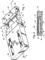
- the three main portions of the fire detector are the electronic compartment 42, the sample chamber 44, which is attached to the electronic compartment 42, and the housing 46 which, as seen in Figures 2 and 4, encloses the sample chamber 44, and which is attached to the electronic compartment 42.
- the electronic compartment 42 contains the circuits shown in Figure 5, including the electronic circuit and the alarm circuit as well as an audible alarm, a visible alarm, and, in one variation, batteries to power the device.
- the source 12 is a laser diode.
- the source 12 emits radiation in the 4.26 micron absorption band of carbon dioxide.
- the filter 24 serves to limit the radiation reaching the detector 26 to the same wavelength band. If the source 12 is a semiconductor laser, the filter 24 is not used.
- the housing 46 includes apertures of which the aperture 48 is typical.
- the aperture 48 is covered by a matrix 62 which supports a membrane 60.
- the membrane 60 is composed of silicon rubber, and the matrix consists of a thin layer of a very permeable fabric such as glass fiber or the material of ladies nylon hosiery.
- the present invention encompasses other membranes that are permeable to carbon dioxide while remaining impermeable to particles of smoke, dust, water, and oil.
- air-cleaning filters are readily available for filtering out particles as small as .01 microns while permitting air to pass through.
- Figures 3 and 4 show a second preferred embodiment which differs from the first preferred embodiment only in the location of the permeable layer 60.
- the permeable layer 60 is attached to the sample chamber 44 rather than to the housing 46.
- the permeable layer spans the passage 30 of the sample chamber 44. Since the passages 30 are the only path by which access is gained to the extended passage 20, it follows that the unwanted particles of smoke, dust, water and oil will be kept out of the extended passage 20 but carbon dioxide is able to reach the extended passage 20 by difusion through the permeable layer and through the passages 30.
- the housing 46 is provided with apertures 48 to permit ambient air to communicate with the space between the housing and the sample chamber.
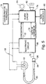
- Figure 5 shows the components that are located in the electronic compartment 42.
- the electronic circuit 66 produces timed pulses of current on the lines 68 to drive the source 12.
- the source emits radiation that travels through the extended passage through the filter 24 and that impinges on the detector 26.
- the detector 26 produces an electrical signal on the line 70 representative of the intensity of the radiation falling upon it. The signal thus produced on the line 60 is applied to the electronic circuit 66.
- AC circuitry is used, and consistent with that approach, the source 12 is pulsed at a rate on the order of 1.0 Hz.
- the constant magnitude of the pulses of current applied to the source 12 results in a series of pulses on the line 70 of constant magnitude. Background radiation falling on the detector 26 is steady, and produces a DC component on the line 70 which is eliminated by the AC circuitry.
- the concentration of carbon dioxide in the extended passage increases, and because the carbon dioxide absorbs some of the radiation emitted by the source 12, the amplitude of the signal on the line 70 decreases.
- the amount of decrease resulting from a particular level of concentration of carbon dioxide gas can be established by calibrating the instrument under controlled conditions.
- the concentration of carbon dioxide is related to the decrease in the amplitude of the signal on the line 70.
- the electronic circuit 66 produces a signal on the line 72 that is representative of the concentration of carbon dioxide.
- the electronic circuit also produces a signal on the line 74 that is related to the rate of change of the concentration of carbon dioxide.
- the signals on the lines 72 and 74 are applied to the alarm circuit 76.
- That circuit also receives a threshold level of concentration from the potentiometer 78 and a threshold level for the rate of change of concentration from the potentiometer 80.
- the alarm circuit 76 compares the concentration of carbon dioxide with the threshold level set on the potentiometer 78 and compares the rate of change of the concentration as represented by the signal on the line 74 with the rate threshold that has been preset on the potentiometer 80.
- false alarms are minimized by requiring that both the concentration and its rate of change must exceed their respective threshold levels before the alarm will be activated.
- the alarm is activated if either the concentration or the rate of change of the concentration exceeds its respective threshold. This mode is necessarily faster, but is likely to produce a greater number of false alarms.
- a compromise between response time and false alarms is achieved by forming a linear combination of the concentration and its rate of change, and by activating the alarm when the linear combination exceeds some threshold.
- Calibration of the fire detector can be accomplished by placing it in a special atmosphere that includes a concentration of carbon dioxide that is considered to be a significant increase, i.e., of the magnitude that might be expected when a fire starts, and by adjusting the potentiometer 78 to gradually lower the threshold level until the alarm is sounded.
- the simple fire detector described above can be installed in industrial buildings, including warehouses, where its early-warning capability and its lack of false alarms should prove invaluable.
Landscapes
- Chemical & Material Sciences (AREA)
- Health & Medical Sciences (AREA)
- Analytical Chemistry (AREA)
- Life Sciences & Earth Sciences (AREA)
- Physics & Mathematics (AREA)
- General Physics & Mathematics (AREA)
- Engineering & Computer Science (AREA)
- Emergency Management (AREA)
- Combustion & Propulsion (AREA)
- Business, Economics & Management (AREA)
- Medicinal Chemistry (AREA)
- Biochemistry (AREA)
- General Health & Medical Sciences (AREA)
- Immunology (AREA)
- Pathology (AREA)
- Food Science & Technology (AREA)
- Investigating Or Analysing Materials By Optical Means (AREA)
- Fire-Detection Mechanisms (AREA)
- Fire Alarms (AREA)
Claims (9)
- Ein Feuerdetektor, der den Aufbau von Kohlendioxid in der Umgebungsluft abfühlt, wobei das Kohlendioxid durch das Feuer erzeugt wird und der Feuerdetektor keine beweglichen Teile besitzt und folgendes aufweist:
eine Quelle (12), die in der Lage ist, Strahlung zu emittieren mit einer mit einem Absorptionsband des Kohlendioxids zusammenfallenden Wellenlänge und mit einem Detektor (26), der ansprechend auf ihn fallende Strahlung ein elektrisches Signal erzeugt;
wobei der Feuerdetektor gekennzeichnet ist durch:eine Probenkammer (44) einschließlich eines Durchlasses (30), der mit der die Probenkammer umgebenden Luft in Verbindung steht, wobei die Probenkammer Mittel (20) aufweist, die einen indirekten Pfad für die emittierte Strahlung durch die erwähnte Probenkammer definieren, wobei die erwähnte Quelle an einem Ende des indirekten Pfades und der Detektor am anderen Ende des indirekten Pfades angeordnet ist;Membranmittel (60), die für Kohlendioxidgas permeabel sind und zwischen dem Durchlaß (30) und der Umgebungsluft angeordnet sind und verhindern, daß Rauch, Staub, Öl und Wasser die Probenkammer erreichen, während gestattet wird, daß Kohlendioxid in die Probenkammer gelangt; undelektronische Mittel (66) elektrisch verbunden mit dem Detektor und ansprechend auf das elektrische durch diesen erzeugte Signal, um mindestens ein Signal zu erzeugen und zwar ausgewählt aus einer Signalgruppe die ein erstes Signal, repräsentativ für die Konzentration des Kohlendioxids in der Probenkammer und ein zweites Signal repräsentativ für die Änderungsgewschwindigkeit der Konzentration des Kohlendioxids in der Probenkammer, aufweist. - Feuerdetektor nach Anspruch 1, wobei folgendes vorgesehen ist:
ein Gehäuse (46) mit einer Öffnung oder Apertur (48) und die Probenkammer derart umgebend, daß der einzige Weg der Verbindung der Probenkammer mit der Umgebungsluft durch die Öffnung geht. - Feuerdetektor nach Anspruch 1, wobei die elektronischen Mittel sowohl das erste Signal als auch das zweite Signal erzeugen und ferner folgendes aufweisen:
Alarmmittel verbunden mit den elektronischen Mitteln und ansprechend auf das erste Signal und auf das zweite Signal zur Erzeugung eines Alarmsignals nur dann, wenn sowohl das erste Signal als auch das zweite Signal ihre entsprechenden voreingestellten Schwellen übersteigen. - Feuerdetektor nach Anspruch 1, wobei ferner folgendes vorgesehen ist:
mit den Elektronikmitteln verbundene Alarmmittel, und zwar ansprechend auf das erste Signal und auf das zweite Signal zur Erzeugung eines Alarmsignals, wenn entweder das erste Signal oder das zweite Signal seinen voreingestellten Schwellenwert übersteigt. - Feuerdetektor nach Anspruch 1, wobei ferner folgendes vorgesehen ist;
Alarmmittel verbunden mit den elektronischen Mitteln und ansprechend auf das erste Signal und auf das zweite Signal zur Erzeugung eines kombinierten Signals, das eine Linearkombination des ersten Signals und des zweiten Signals ist und um ein Alarmsignal dann zu erzeugen, wenn das kombinierte Signal eine voreingestellte Schwelle übersteigt. - Feuerdetektor nach einem der vorhergehenden Ansprüche, wobei die Membranmittel ferner einen Film bestehend aus Silicongummi aufweisen.
- Feuerdetektor nach Anspruch 6, wobei die Membranmittel ferner einen Film oder eine Schicht aus Silicongummi aufweisen und ein Flächenelement aus einem Matrix oder Trägermaterial (62), an dem der Film oder die Schicht zum Zwecke der Verstärkung angebracht ist.
- Feuerdetektor nach Anspruch 1, wobei die Quelle Strahlung in dem 4,26 Mikron Absorptionsband des Kohlendioxids emittiert.
- Feuerdetektor nach Anspruch 1, wobei ferner in Kombination ein schmales Bandpaßfilter (24) in dem indirekten Pfad angeordnet ist, zwischen der Quelle und dem Detektor und Strahlung in dem 4,26 Mikron Absorptionsband des Kohlendioxids überträgt.
Applications Claiming Priority (3)
| Application Number | Priority Date | Filing Date | Title |
|---|---|---|---|
| US503214 | 1990-04-02 | ||
| US07/503,214 US5053754A (en) | 1990-04-02 | 1990-04-02 | Simple fire detector |
| PCT/US1991/002223 WO1991015836A1 (en) | 1990-04-02 | 1991-03-29 | Simple fire detector |
Publications (3)
| Publication Number | Publication Date |
|---|---|
| EP0474860A1 EP0474860A1 (de) | 1992-03-18 |
| EP0474860A4 EP0474860A4 (en) | 1992-12-09 |
| EP0474860B1 true EP0474860B1 (de) | 1998-02-04 |
Family
ID=24001182
Family Applications (1)
| Application Number | Title | Priority Date | Filing Date |
|---|---|---|---|
| EP91908300A Expired - Lifetime EP0474860B1 (de) | 1990-04-02 | 1991-03-29 | Einfacher Feuerdetektor |
Country Status (14)
| Country | Link |
|---|---|
| US (1) | US5053754A (de) |
| EP (1) | EP0474860B1 (de) |
| JP (1) | JP2542306B2 (de) |
| CN (1) | CN1020055C (de) |
| AR (1) | AR245305A1 (de) |
| AU (1) | AU641246B2 (de) |
| CA (1) | CA2058928C (de) |
| CZ (1) | CZ280824B6 (de) |
| DE (1) | DE69128859T2 (de) |
| MX (1) | MX167215B (de) |
| MY (1) | MY105294A (de) |
| NZ (1) | NZ237465A (de) |
| PL (1) | PL289708A1 (de) |
| WO (1) | WO1991015836A1 (de) |
Families Citing this family (53)
| Publication number | Priority date | Publication date | Assignee | Title |
|---|---|---|---|---|
| US5345830A (en) * | 1988-08-30 | 1994-09-13 | Symtron Systems, Inc. | Fire fighting trainer and apparatus including a temperature sensor |
| US5335559A (en) * | 1988-08-30 | 1994-08-09 | Symtron Systems, Inc. | Fire fighting trainer and apparatus |
| US5369397A (en) * | 1989-09-06 | 1994-11-29 | Gaztech International Corporation | Adaptive fire detector |
| US5157380A (en) * | 1991-02-15 | 1992-10-20 | Electric Power Research Institute, Inc. | Overheated electrical insulation detector |
| US5376924A (en) * | 1991-09-26 | 1994-12-27 | Hochiki Corporation | Fire sensor |
| US5340986A (en) * | 1991-11-18 | 1994-08-23 | Gaztech International Corporation | Diffusion-type gas sample chamber |
| DE4301457A1 (de) * | 1993-01-21 | 1994-08-04 | E T R Elektronik Technologie R | Detektor für brennbare Gase insbesondere Methan |
| US6107925A (en) * | 1993-06-14 | 2000-08-22 | Edwards Systems Technology, Inc. | Method for dynamically adjusting criteria for detecting fire through smoke concentration |
| US5767776A (en) * | 1996-01-29 | 1998-06-16 | Engelhard Sensor Technologies, Inc. | Fire detector |
| US5592147A (en) * | 1993-06-14 | 1997-01-07 | Wong; Jacob Y. | False alarm resistant fire detector with improved performance |
| JPH0744783A (ja) * | 1993-08-04 | 1995-02-14 | Nohmi Bosai Ltd | 火災感知装置 |
| WO1995006926A1 (en) * | 1993-08-30 | 1995-03-09 | Gaztech International Corporation | Adaptive fire detector |
| FR2712390B1 (fr) * | 1993-11-12 | 1996-02-09 | Saphir | Dispositif de détection de gaz par absorption infrarouge. |
| US5617077A (en) * | 1995-05-03 | 1997-04-01 | Pittway Corporation | Testable photoelectric detector |
| US5945924A (en) * | 1996-01-29 | 1999-08-31 | Marman; Douglas H. | Fire and smoke detection and control system |
| AU1755597A (en) * | 1996-01-29 | 1997-08-20 | Engelhard Sensor Technologies, Inc. | Method for dynamically adjusting fire detection criteria |
| AUPN968996A0 (en) * | 1996-05-06 | 1996-05-30 | Vision Products Pty Ltd | Filter integrity monitoring system |
| US5886348A (en) * | 1997-02-14 | 1999-03-23 | American Intell-Sensors Corporation | Non-dispersive infrared gas analyzer with interfering gas correction |
| US5831524A (en) * | 1997-04-29 | 1998-11-03 | Pittway Corporation | System and method for dynamic adjustment of filtering in an alarm system |
| US5892140A (en) * | 1997-04-30 | 1999-04-06 | Honeywell Inc. | Micromachined inferential opto-thermal gas sensor |
| US5831537A (en) * | 1997-10-27 | 1998-11-03 | Slc Technologies, Inc. | Electrical current saving combined smoke and fire detector |
| US6250133B1 (en) * | 1998-01-06 | 2001-06-26 | Edwards Systems Technology, Inc. | Method for detecting venting of a combustion appliance within an improper space |
| US6229439B1 (en) | 1998-07-22 | 2001-05-08 | Pittway Corporation | System and method of filtering |
| US6222456B1 (en) | 1998-10-01 | 2001-04-24 | Pittway Corporation | Detector with variable sample rate |
| US6151189A (en) * | 1998-12-28 | 2000-11-21 | Western Digital Corporation | Disk drive spindle motor with embedded ionizing source for static charge dissipation |
| US6225910B1 (en) | 1999-12-08 | 2001-05-01 | Gentex Corporation | Smoke detector |
| US6876305B2 (en) * | 1999-12-08 | 2005-04-05 | Gentex Corporation | Compact particle sensor |
| US6344798B1 (en) * | 2001-04-27 | 2002-02-05 | Edwards Systems Technology, Inc. | Using carbon dioxide to indicate oxygen depletion |
| US6822216B2 (en) | 2002-01-08 | 2004-11-23 | Honeywell International, Inc. | Obscuration detector |
| SE524900C2 (sv) | 2002-07-22 | 2004-10-19 | Senseair Ab | Gasanalyserande arrangemang |
| GB2392721A (en) * | 2002-09-03 | 2004-03-10 | E2V Tech Uk Ltd | Gas sensors |
| CN100356162C (zh) * | 2004-07-07 | 2007-12-19 | 深圳迈瑞生物医疗电子股份有限公司 | 基于光源调制测量气体浓度的方法和装置 |
| US7775292B1 (en) * | 2004-07-26 | 2010-08-17 | Romanco Ernest K | CO2 fire suppression monitoring apparatus and method |
| SE0501399L (sv) * | 2005-06-17 | 2006-12-18 | Xcounter Ab | Detektorhopsättning |
| US7214939B1 (en) | 2005-11-21 | 2007-05-08 | Airware, Inc. | Ultra low power NDIR carbon dioxide sensor fire detector |
| US7616126B2 (en) * | 2006-07-18 | 2009-11-10 | Gentex Corporation | Optical particle detectors |
| JP2008065404A (ja) * | 2006-09-05 | 2008-03-21 | Nohmi Bosai Ltd | 火災感知器 |
| DE202009009349U1 (de) | 2008-12-23 | 2009-10-01 | Glinberg, Valeriy, Dipl.-Ing. | Feuerboje, die Einwegeinrichtung der Früherkennung des Brandes, der Feuermeldeanlage und der Benachrichtigung |
| US8004782B1 (en) | 2009-03-19 | 2011-08-23 | Western Digital Technologies, Inc. | Tester with virtual ground |
| US8707759B2 (en) * | 2010-03-17 | 2014-04-29 | Carrier Corporation | Flue gas sensor with water barrier member |
| US8701465B2 (en) * | 2011-04-28 | 2014-04-22 | Honeywell International Inc. | Photoacoustic sensor diffusion membrane attachment structure |
| CN102231222B (zh) * | 2011-06-08 | 2012-08-15 | 无锡金桥自动化技术有限公司 | 电气火灾监控方法 |
| US8922381B2 (en) | 2011-07-20 | 2014-12-30 | Logico2 Online Sarl | Device and system for gas leakage detection and alarm |
| CN102800172A (zh) * | 2012-07-27 | 2012-11-28 | 浙江三峰电子有限公司 | 家用气体报警器及其标定方法 |
| KR20150090195A (ko) * | 2012-11-27 | 2015-08-05 | 엑스트랄리스 테크놀로지 리미티드 | 화재 감지 |
| CN103366495B (zh) * | 2013-07-11 | 2015-08-05 | 合肥工业大学 | 一种吸气式高灵敏度烟颗粒探测器及其应用 |
| DE102015004458B4 (de) | 2014-06-26 | 2016-05-12 | Elmos Semiconductor Aktiengesellschaft | Vorrichtung und Verfahren für einen klassifizierenden, rauchkammerlosen Luftzustandssensor zur Prognostizierung eines folgenden Betriebszustands |
| CN104217518A (zh) * | 2014-07-28 | 2014-12-17 | 徐州中安科技股份有限公司 | 一种智能火灾报警器及其工作方法 |
| DE102014019172B4 (de) | 2014-12-17 | 2023-12-07 | Elmos Semiconductor Se | Vorrichtung und Verfahren zur Unterscheidung von festen Objekten, Kochdunst und Rauch mit einem kompensierenden optischen Messsystem |
| DE102014019773B4 (de) | 2014-12-17 | 2023-12-07 | Elmos Semiconductor Se | Vorrichtung und Verfahren zur Unterscheidung von festen Objekten, Kochdunst und Rauch mittels des Displays eines Mobiltelefons |
| CA3020553A1 (en) | 2017-10-17 | 2019-04-17 | Pierre Desjardins | Interconnecting detector |
| CN111365730B (zh) * | 2018-12-26 | 2022-06-24 | Abb瑞士股份有限公司 | 火焰检测器 |
| CN111467886B (zh) | 2020-03-31 | 2021-11-19 | 苏州浪潮智能科技有限公司 | 一种火灾监控系统及集装箱式数据中心系统 |
Family Cites Families (8)
| Publication number | Priority date | Publication date | Assignee | Title |
|---|---|---|---|---|
| CH641584A5 (de) * | 1979-02-26 | 1984-02-29 | Cerberus Ag | Brandmelder. |
| JPS59103191A (ja) * | 1982-12-03 | 1984-06-14 | シャープ株式会社 | 火災警報装置 |
| US4738266A (en) * | 1983-05-09 | 1988-04-19 | Thatcher John B | Apnoea monitor |
| US4496817A (en) * | 1983-07-07 | 1985-01-29 | General Electric Company | Automatic fire detection for a microwave oven |
| JPH0229980B2 (ja) * | 1983-11-04 | 1990-07-03 | Showa Denko Kk | Puropangasunodonosokuteihohooyobisonosochi |
| US4709150A (en) * | 1986-03-18 | 1987-11-24 | Burough Irvin G | Method and apparatus for detecting gas |
| JP2949286B2 (ja) * | 1987-08-26 | 1999-09-13 | 松下電工株式会社 | 減光式二酸化炭素濃度感知器 |
| US4928687A (en) * | 1988-10-11 | 1990-05-29 | The University Of Florida | CO2 diagnostic monitor |
-
1990
- 1990-04-02 US US07/503,214 patent/US5053754A/en not_active Expired - Lifetime
-
1991
- 1991-03-18 NZ NZ237465A patent/NZ237465A/en unknown
- 1991-03-25 MY MYPI91000490A patent/MY105294A/en unknown
- 1991-03-29 AU AU76994/91A patent/AU641246B2/en not_active Ceased
- 1991-03-29 CA CA002058928A patent/CA2058928C/en not_active Expired - Fee Related
- 1991-03-29 JP JP3507993A patent/JP2542306B2/ja not_active Expired - Lifetime
- 1991-03-29 WO PCT/US1991/002223 patent/WO1991015836A1/en active IP Right Grant
- 1991-03-29 EP EP91908300A patent/EP0474860B1/de not_active Expired - Lifetime
- 1991-03-29 DE DE69128859T patent/DE69128859T2/de not_active Expired - Fee Related
- 1991-04-01 CN CN91102170A patent/CN1020055C/zh not_active Expired - Lifetime
- 1991-04-02 PL PL28970891A patent/PL289708A1/xx unknown
- 1991-04-02 AR AR91319379A patent/AR245305A1/es active
- 1991-04-02 CZ CS91901A patent/CZ280824B6/cs not_active IP Right Cessation
- 1991-04-02 MX MX025173A patent/MX167215B/es unknown
Also Published As
| Publication number | Publication date |
|---|---|
| US5053754A (en) | 1991-10-01 |
| NZ237465A (en) | 1994-01-26 |
| PL289708A1 (en) | 1992-02-24 |
| WO1991015836A1 (en) | 1991-10-17 |
| AU641246B2 (en) | 1993-09-16 |
| CZ280824B6 (cs) | 1996-04-17 |
| CA2058928A1 (en) | 1991-10-03 |
| JPH04507161A (ja) | 1992-12-10 |
| EP0474860A4 (en) | 1992-12-09 |
| AR245305A1 (es) | 1993-12-30 |
| DE69128859D1 (de) | 1998-03-12 |
| DE69128859T2 (de) | 1998-09-10 |
| CA2058928C (en) | 1996-07-09 |
| CS90191A3 (en) | 1992-06-17 |
| CN1057538A (zh) | 1992-01-01 |
| CN1020055C (zh) | 1993-03-10 |
| MY105294A (en) | 1994-09-30 |
| EP0474860A1 (de) | 1992-03-18 |
| MX167215B (es) | 1993-03-09 |
| AU7699491A (en) | 1991-10-30 |
| JP2542306B2 (ja) | 1996-10-09 |
Similar Documents
| Publication | Publication Date | Title |
|---|---|---|
| EP0474860B1 (de) | Einfacher Feuerdetektor | |
| US5103096A (en) | Rapid fire detector | |
| US5966077A (en) | Fire detector | |
| US5767776A (en) | Fire detector | |
| US6166647A (en) | Fire detector | |
| US6107925A (en) | Method for dynamically adjusting criteria for detecting fire through smoke concentration | |
| US5592147A (en) | False alarm resistant fire detector with improved performance | |
| US5691704A (en) | Practical and improved fire detector | |
| US5945924A (en) | Fire and smoke detection and control system | |
| US3922656A (en) | Sensing presence of fire | |
| EP0078442B1 (de) | Branddetektoranlage mit IR und UV Verhältnisdetektor | |
| US7176460B1 (en) | Passive NDIR gas sensor fire detector | |
| US7551277B2 (en) | Particle monitors and method(s) therefor | |
| US7214939B1 (en) | Ultra low power NDIR carbon dioxide sensor fire detector | |
| AU2010200806A1 (en) | Improvement(s) Related to Particle Monitors and Method(s) Therefor | |
| TW413800B (en) | Electrical current saving combined smoke and fire detector | |
| AU2007203107B2 (en) | Improvement(s) related to particle monitors and method(s) therefor | |
| CA2598745A1 (en) | Improvement(s) related to particle monitors and method(s) therefor |
Legal Events
| Date | Code | Title | Description |
|---|---|---|---|
| PUAI | Public reference made under article 153(3) epc to a published international application that has entered the european phase |
Free format text: ORIGINAL CODE: 0009012 |
|
| 17P | Request for examination filed |
Effective date: 19911129 |
|
| AK | Designated contracting states |
Kind code of ref document: A1 Designated state(s): DE FR GB IT SE |
|
| A4 | Supplementary search report drawn up and despatched |
Effective date: 19921019 |
|
| AK | Designated contracting states |
Kind code of ref document: A4 Designated state(s): DE FR GB IT SE |
|
| 17Q | First examination report despatched |
Effective date: 19951227 |
|
| GRAG | Despatch of communication of intention to grant |
Free format text: ORIGINAL CODE: EPIDOS AGRA |
|
| GRAG | Despatch of communication of intention to grant |
Free format text: ORIGINAL CODE: EPIDOS AGRA |
|
| GRAH | Despatch of communication of intention to grant a patent |
Free format text: ORIGINAL CODE: EPIDOS IGRA |
|
| GRAH | Despatch of communication of intention to grant a patent |
Free format text: ORIGINAL CODE: EPIDOS IGRA |
|
| GRAA | (expected) grant |
Free format text: ORIGINAL CODE: 0009210 |
|
| AK | Designated contracting states |
Kind code of ref document: B1 Designated state(s): DE FR GB IT SE |
|
| PG25 | Lapsed in a contracting state [announced via postgrant information from national office to epo] |
Ref country code: IT Free format text: LAPSE BECAUSE OF FAILURE TO SUBMIT A TRANSLATION OF THE DESCRIPTION OR TO PAY THE FEE WITHIN THE PRE;WARNING: LAPSES OF ITALIAN PATENTS WITH EFFECTIVE DATE BEFORE 2007 MAY HAVE OCCURRED AT ANY TIME BEFORE 2007. THE CORRECT EFFECTIVE DATE MAY BE DIFFERENT FROM THE ONE RECORDED.SCRIBED TIME-LIMIT Effective date: 19980204 |
|
| REF | Corresponds to: |
Ref document number: 69128859 Country of ref document: DE Date of ref document: 19980312 |
|
| PG25 | Lapsed in a contracting state [announced via postgrant information from national office to epo] |
Ref country code: SE Free format text: LAPSE BECAUSE OF FAILURE TO SUBMIT A TRANSLATION OF THE DESCRIPTION OR TO PAY THE FEE WITHIN THE PRESCRIBED TIME-LIMIT Effective date: 19980504 |
|
| ET | Fr: translation filed | ||
| PLBE | No opposition filed within time limit |
Free format text: ORIGINAL CODE: 0009261 |
|
| STAA | Information on the status of an ep patent application or granted ep patent |
Free format text: STATUS: NO OPPOSITION FILED WITHIN TIME LIMIT |
|
| 26N | No opposition filed | ||
| PGFP | Annual fee paid to national office [announced via postgrant information from national office to epo] |
Ref country code: GB Payment date: 20000302 Year of fee payment: 10 Ref country code: FR Payment date: 20000302 Year of fee payment: 10 |
|
| PG25 | Lapsed in a contracting state [announced via postgrant information from national office to epo] |
Ref country code: GB Free format text: LAPSE BECAUSE OF NON-PAYMENT OF DUE FEES Effective date: 20010329 |
|
| GBPC | Gb: european patent ceased through non-payment of renewal fee |
Effective date: 20010329 |
|
| PG25 | Lapsed in a contracting state [announced via postgrant information from national office to epo] |
Ref country code: FR Free format text: LAPSE BECAUSE OF NON-PAYMENT OF DUE FEES Effective date: 20011130 |
|
| REG | Reference to a national code |
Ref country code: FR Ref legal event code: ST |
|
| PGFP | Annual fee paid to national office [announced via postgrant information from national office to epo] |
Ref country code: DE Payment date: 20011231 Year of fee payment: 11 |
|
| PG25 | Lapsed in a contracting state [announced via postgrant information from national office to epo] |
Ref country code: DE Free format text: LAPSE BECAUSE OF NON-PAYMENT OF DUE FEES Effective date: 20021001 |