EP0474322A2 - Glass fibre reinforced plastic leafspring - Google Patents
Glass fibre reinforced plastic leafspring Download PDFInfo
- Publication number
- EP0474322A2 EP0474322A2 EP91250057A EP91250057A EP0474322A2 EP 0474322 A2 EP0474322 A2 EP 0474322A2 EP 91250057 A EP91250057 A EP 91250057A EP 91250057 A EP91250057 A EP 91250057A EP 0474322 A2 EP0474322 A2 EP 0474322A2
- Authority
- EP
- European Patent Office
- Prior art keywords
- spiral spring
- spring support
- force application
- support
- grp
- Prior art date
- Legal status (The legal status is an assumption and is not a legal conclusion. Google has not performed a legal analysis and makes no representation as to the accuracy of the status listed.)
- Withdrawn
Links
Images
Classifications
-
- F—MECHANICAL ENGINEERING; LIGHTING; HEATING; WEAPONS; BLASTING
- F16—ENGINEERING ELEMENTS AND UNITS; GENERAL MEASURES FOR PRODUCING AND MAINTAINING EFFECTIVE FUNCTIONING OF MACHINES OR INSTALLATIONS; THERMAL INSULATION IN GENERAL
- F16F—SPRINGS; SHOCK-ABSORBERS; MEANS FOR DAMPING VIBRATION
- F16F1/00—Springs
- F16F1/36—Springs made of rubber or other material having high internal friction, e.g. thermoplastic elastomers
- F16F1/366—Springs made of rubber or other material having high internal friction, e.g. thermoplastic elastomers made of fibre-reinforced plastics, i.e. characterised by their special construction from such materials
- F16F1/368—Leaf springs
Definitions
- the invention relates to a GRP leaf spring for the resilient connection of machine elements with a defined deformation path.
- a resilient wheel or axle guide element in vehicle construction, but also as an element for realizing the defined spring and return travel or defined forces in device technology mechanisms, is considered appropriate.
- a number of plastic components for the axle area of vehicles have already been implemented.
- the production of fiber-reinforced plastic leaf springs according to DE-OS 34 34 375 is known. However, these are not able to achieve defined deformation values and thus perform handlebar functions.
- a wheel suspension for vehicles according to DE-OS 35 30 353 is known. It has a resilient wheel guide element, which consists of a standing, closed, trapezoidal ring made of plastic, which is manufactured using winding technology. The sides running in the horizontal direction fulfill the function of resilient axle links.
- the chosen one elaborate winding technology in conjunction with the trapezoidal ring does not allow the spring-loaded axle links to be pre-bent in the unloaded state and thus does not offer the possibility of optimizing the deformation path of the force application point.
- the aim of the invention is to dimension and design a spiral spring support that is easy and inexpensive to manufacture and that enables the deformation path to be optimized, with functional integration between suspension and articulation or guidance and resetting being achieved.
- the object of the invention is to provide a defined spiral spring support with only one link, the optimal function of which is achieved without additional technical means.
- the parameters are set in coordination with the selected cross-sectional profiles according to the parabolic or hyperbolic spring.
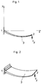
- FIG. 2 An exemplary embodiment is to be explained with FIG. 2.
- a spiral spring support 3 with a parabolic course of thickness between clamping 1 and force application point 2 made of fiber composite material is shown.
- the choice of the corresponding parameters a; b; t in the equation over the spring travel y minimizes the change in the force application point 2 in the horizontal direction ( ⁇ x). This is achieved by means of compensation for the horizontal extension due to rotation about the clamping 1 by compressing the spiral spring support 3 in the x direction.
- the mathematical modeling of the shape of the spiral spring support 3 can be explained with FIG. 1.
- the parameter t fixes the force application point 2 for clamping 1 in accordance with the structural boundary conditions.
- the parameter b allows the carrier to be designed as a full sine or half sine wave.
- the size a of the pre-curvature and thus taking into account the position of the force application point 2 for clamping 1, the desired deformation path in the x- and y-directions can be determined by the parameter a determine and check by calculation. Due to the presence of the thickness or width profile, corresponding to the parabolic or hyperbolic spring, the coordinates of the molding tool can be mathematically described for any point.
Abstract
Description
Die Erfindung betrifft eine GFK-Blattfeder zur federnden Verbindung von Maschinenelementen bei definiertem Verformungsweg. Ein Einsatz als federndes Rad- oder Achsführungselement im Fahrzeugbau, aber auch als Element zur Realisierung des definierten Feder- und Rückstellweges bzw. definierter Kräfte bei Mechanismen der Gerätetechnik wird als zweckmäßig erachtet.The invention relates to a GRP leaf spring for the resilient connection of machine elements with a defined deformation path. Use as a resilient wheel or axle guide element in vehicle construction, but also as an element for realizing the defined spring and return travel or defined forces in device technology mechanisms, is considered appropriate.
Mit dem Ziel, vor allem die ungefederten Massen von Fahrzeugen zu verringern, wurden bereits eine Reihe von Kunststoffbauteilen für den Achsbereich von Fahrzeugen realisiert. So ist die Herstellung von faserverstärkten Kunststoffblattfedern nach DE-OS 34 34 375 bekannt. Diese sind aber nicht in der Lage, definierte Verformungswerte zu realisieren und damit Lenkerfunktionen zu erfüllen. Weiterhin ist eine Radaufhängung für Fahrzeuge gemäß DE-OS 35 30 353 bekannt. Sie weist ein federndes Radführungselement auf, das aus einem stehend angeordneten, geschlossenen, trapezförmigen Ring aus Kunststoff besteht, der in Wickeltechnologie hergestellt wird. Die in horizontaler Richtung verlaufenden Seiten erfüllen die Funktion von federnden Achslenkern. Die gewählte aufwendige Wickeltechnologie gestattet in Verbindung mit dem trapezförmigen Ring keine gezielte Vorkrümmung der federnden Achslenker im unbelasteten Zustand und bietet damit nicht die Möglichkeit der Optimierung des Verformungsweges des Kraftangriffspunktes.With the aim of reducing the unsprung mass of vehicles, a number of plastic components for the axle area of vehicles have already been implemented. The production of fiber-reinforced plastic leaf springs according to DE-OS 34 34 375 is known. However, these are not able to achieve defined deformation values and thus perform handlebar functions. Furthermore, a wheel suspension for vehicles according to DE-OS 35 30 353 is known. It has a resilient wheel guide element, which consists of a standing, closed, trapezoidal ring made of plastic, which is manufactured using winding technology. The sides running in the horizontal direction fulfill the function of resilient axle links. The chosen one elaborate winding technology in conjunction with the trapezoidal ring does not allow the spring-loaded axle links to be pre-bent in the unloaded state and thus does not offer the possibility of optimizing the deformation path of the force application point.
Ziel der Erfindung ist es, einen Biegefederträger zu dimensionieren und zu gestalten, der leicht und kostengünstig herstellbar ist und eine Optimierung des Verformungsweges ermöglicht, wobei eine Funktionsintegration zwischen Federung und Anlenkung bzw. Führung und Rückstellung erreicht wird.The aim of the invention is to dimension and design a spiral spring support that is easy and inexpensive to manufacture and that enables the deformation path to be optimized, with functional integration between suspension and articulation or guidance and resetting being achieved.
Aufgabe der Erfindung ist es, einen definierten Biegefederträger mit nur einem Lenker zu schaffen, dessen optimale Funktionserfüllung ohne zusätzliche technische Mittel erreicht wird.The object of the invention is to provide a defined spiral spring support with only one link, the optimal function of which is achieved without additional technical means.
Erfindungsgemäß wird diese Aufgabe dadurch gelöst, daß der einseitig eingespannte Biegefederträger im unbelasteten Zustand eine Vorkrümmung nach der Funktion y(x) = tx+a sin (bx) aufweist, deren Parameter t, a und b unter Berücksichtigung baulicher Randbedingungen eine Vorausberechnung und gezielte Optimierung des Verformungsverhaltens entsprechend den Anforderungen des Anwenders gestatten. Dabei erfolgt die Parameterfestlegung in Abstimmung mit den gewählten Querschnittsverläufen entsprechend Parabel- oder Hyperbelfeder. Die Möglichkeit der mathematischen Beschreibung der Konturen des Formwerkzeuges gestattet eine ökonomisch günstige Herstellung des Biegefederträgers, durch dessen Anwendung als federnde Achsanlenkung die Anforderungen an eine exakte Radführung kostengünstig realisierbar sind.According to the invention, this object is achieved in that the cantilever spring washer, in the unloaded state, has a pre-curvature according to the function y (x) = tx + a sin (bx), the parameters t, a and b of which, taking structural boundary conditions into account, pre-calculation and targeted optimization the deformation behavior according to the requirements of the user. The parameters are set in coordination with the selected cross-sectional profiles according to the parabolic or hyperbolic spring. The possibility The mathematical description of the contours of the molding tool allows an economically favorable production of the spiral spring carrier, by its use as a spring axle linkage, the requirements for exact wheel guidance can be realized inexpensively.
Mit Fig. 2 soll ein Ausführungsbeispiel erläutert werden. Es wird ein Biegefederträger 3 mit parabolischem Dickenverlauf zwischen Einspannung 1 und Kraftangriffspunkt 2 aus Faserverbundwerkstoff gezeigt. Beim dargestellten Beispiel wurde durch die Wahl der entsprechenden Parameter a; b; t in der Gleichung über dem Federweg y eine Minimierung der Veränderung des Kraftangriffspunktes 2 in horizontaler Richtung (Δx) erreicht. Dies wird mittels Kompensation der horizontalen Verlängerung infolge Drehung um die Einspannung 1 durch ein Zusammendrücken des Biegefederträgers 3 in x-Richtung realisiert.
Die mathematische Modellierung der Form des Biegefederträgers 3 ist mit Fig. 1 erläuterbar.
Bei der mathematischen Beschreibung des Biegefederträgers 3 wird mit der Funktion
![]()
die neutrale Faser dargestellt.
Dabei erfolgt mit dem Parameter t eine Fixierung des Kraftangriffspunktes 2 zur Einspannung 1 entsprechend den baulichen Randbedingungen. Der Parameter b gestattet eine Gestaltung des Trägers als Sinusvoll- oder Sinushalbwelle. In Abstimmung mit den baulichen Restriktionen läßt sich durch den Parameter a die Größe der Vorkrümmung und damit unter Berücksichtigung der Lage des Kraftangriffspunktes 2 zur Einspannung 1 der gewünschte Verformungsweg in x- und y-Richtung bestimmen und durch Berechnung überprüfen. Durch das Vorliegen des Dicken- bzw. Breitenverlaufes, entsprchend Parabel- oder Hyperbelfeder, sind die Koordinaten des Formwerkzeuges für jeden beliebigen Punkt mathematisch beschreibbar.An exemplary embodiment is to be explained with FIG. 2. A
The mathematical modeling of the shape of the
In the mathematical description of the
![]()
the neutral fiber is shown.
The parameter t fixes the
Nachstehende Aufstellung enthält die Bezugszeichen und technischen Begriffsbestimmungen der vorstehend näher bezeichneten Erfindung "GFK-Blattfeder".
- 1
- Einspannung
- 2
- Kraftangriffspunkt
- 3
- Biegefederträger
- x
- Richtung
- y
- Richtung
- t
- Parameter
- b
- Parameter
- a
- Parameter
- 1
- Restraint
- 2nd
- Force application point
- 3rd
- Spiral spring support
- x
- direction
- y
- direction
- t
- parameter
- b
- parameter
- a
- parameter
Claims (3)
Applications Claiming Priority (2)
| Application Number | Priority Date | Filing Date | Title |
|---|---|---|---|
| DD338671 | 1990-03-14 | ||
| DD33867190A DD292509A5 (en) | 1990-03-14 | 1990-03-14 | GRP BLATTFEDER |
Publications (2)
| Publication Number | Publication Date |
|---|---|
| EP0474322A2 true EP0474322A2 (en) | 1992-03-11 |
| EP0474322A3 EP0474322A3 (en) | 1992-11-04 |
Family
ID=5617049
Family Applications (1)
| Application Number | Title | Priority Date | Filing Date |
|---|---|---|---|
| EP19910250057 Withdrawn EP0474322A3 (en) | 1990-03-14 | 1991-03-06 | Glass fibre reinforced plastic leafspring |
Country Status (2)
| Country | Link |
|---|---|
| EP (1) | EP0474322A3 (en) |
| DD (1) | DD292509A5 (en) |
Cited By (2)
| Publication number | Priority date | Publication date | Assignee | Title |
|---|---|---|---|---|
| DE4314807A1 (en) * | 1993-05-05 | 1994-03-31 | Gaertner Peter Prof Dr Ing Hab | Pref. fibrous composite material forming body - is hollow or filled and is pre-curved longitudinally. |
| US9676920B2 (en) | 2007-11-27 | 2017-06-13 | Basell Poliolefine Italia S.R.L. | Polyolefin nanocomposites materials |
Citations (2)
| Publication number | Priority date | Publication date | Assignee | Title |
|---|---|---|---|---|
| DE1164757B (en) * | 1958-07-23 | 1964-03-05 | Minnesota Mining & Mfg | Glass reinforced plastic leaf springs and process for their manufacture |
| EP0249539A1 (en) * | 1986-06-09 | 1987-12-16 | AEROSPATIALE Société Nationale Industrielle | Vehicle suspension for a two-wheel axle, elastic return system for each wheel of the axle, and vehicle comprising such a suspension or such an elastic return system |
-
1990
- 1990-03-14 DD DD33867190A patent/DD292509A5/en not_active IP Right Cessation
-
1991
- 1991-03-06 EP EP19910250057 patent/EP0474322A3/en not_active Withdrawn
Patent Citations (2)
| Publication number | Priority date | Publication date | Assignee | Title |
|---|---|---|---|---|
| DE1164757B (en) * | 1958-07-23 | 1964-03-05 | Minnesota Mining & Mfg | Glass reinforced plastic leaf springs and process for their manufacture |
| EP0249539A1 (en) * | 1986-06-09 | 1987-12-16 | AEROSPATIALE Société Nationale Industrielle | Vehicle suspension for a two-wheel axle, elastic return system for each wheel of the axle, and vehicle comprising such a suspension or such an elastic return system |
Non-Patent Citations (1)
| Title |
|---|
| KUNSTSTOFFE Bd. 75, Nr. 2, Februar 1985, MUENCHEN Seiten 100 - 104; DIPL.ING.T.GOETTE ET AL.: 'grundlagen der dimensionierung von nutzfahrzeugen-blattfedern aus f.-k. verbunden' * |
Cited By (3)
| Publication number | Priority date | Publication date | Assignee | Title |
|---|---|---|---|---|
| DE4314807A1 (en) * | 1993-05-05 | 1994-03-31 | Gaertner Peter Prof Dr Ing Hab | Pref. fibrous composite material forming body - is hollow or filled and is pre-curved longitudinally. |
| US9676920B2 (en) | 2007-11-27 | 2017-06-13 | Basell Poliolefine Italia S.R.L. | Polyolefin nanocomposites materials |
| US10214625B2 (en) | 2007-11-27 | 2019-02-26 | Basell Poliolefine Italia S.R.L. | Polyolefin nanocomosites materials |
Also Published As
| Publication number | Publication date |
|---|---|
| EP0474322A3 (en) | 1992-11-04 |
| DD292509A5 (en) | 1991-08-01 |
Similar Documents
| Publication | Publication Date | Title |
|---|---|---|
| DE69908714T2 (en) | Coil compression spring for a vehicle wheel suspension | |
| DE2658835C3 (en) | Suspension strut mounting with roller bearings | |
| DE102010046495B3 (en) | Joint of an articulated vehicle | |
| DE102009029299A1 (en) | vibration | |
| DE2517799A1 (en) | HANGING DEVICE FOR THE BODY AND THE ENGINE OF A CAR | |
| DE2660079B1 (en) | Adjustment device for a rail vehicle wheelset in a biaxial or multi-axle bogie | |
| DE4021314C2 (en) | ||
| DE102013210046A1 (en) | Carrier assembly for a suspension damper | |
| DE102005015089B4 (en) | Suspension for a vehicle | |
| EP0364713A1 (en) | Wheel suspension | |
| EP2605923A1 (en) | Pneumatic spring strut having a resilient piston bearing | |
| WO2011095242A1 (en) | Pneumatic spring device for a rail vehicle | |
| DE102010035188A1 (en) | Strut slide bearing for steered wheel of motor vehicle i.e. two-track vehicle, has guide ring comprising reinforcement that is enclosed with material of ring such that free surface of reinforcement is cooperated with cap or sliding washer | |
| DE3119361C2 (en) | Joint between a push strut of a wheel suspension of a motor vehicle and a connection fitting on the vehicle | |
| EP0474322A2 (en) | Glass fibre reinforced plastic leafspring | |
| DE102015225824A1 (en) | Transverse leaf spring system | |
| DE1908373A1 (en) | Air spring for vehicles | |
| DE8223449U1 (en) | Spring and damping device for the wheel suspension of vehicles | |
| DE10041200B4 (en) | Suspension strut with fall compensation | |
| DE7505115U (en) | Telescopic shock absorber that can be used as a straight guide element in an independent wheel suspension | |
| DE8022504U1 (en) | SUN VISOR FOR MOTOR VEHICLES | |
| DE2226429C3 (en) | Sun visor with a pivot bearing, in particular for vehicles | |
| DE1580480A1 (en) | Independent front suspension | |
| DE102016220376A1 (en) | Radführungseinrichtung | |
| DE3637281A1 (en) | Spring bracket which can be fixed on the frame of a chassis |
Legal Events
| Date | Code | Title | Description |
|---|---|---|---|
| PUAI | Public reference made under article 153(3) epc to a published international application that has entered the european phase |
Free format text: ORIGINAL CODE: 0009012 |
|
| AK | Designated contracting states |
Kind code of ref document: A2 Designated state(s): ES FR GB IT NL |
|
| PUAL | Search report despatched |
Free format text: ORIGINAL CODE: 0009013 |
|
| AK | Designated contracting states |
Kind code of ref document: A3 Designated state(s): ES FR GB IT NL |
|
| STAA | Information on the status of an ep patent application or granted ep patent |
Free format text: STATUS: THE APPLICATION IS DEEMED TO BE WITHDRAWN |
|
| 18D | Application deemed to be withdrawn |
Effective date: 19930505 |