EP0474085B1 - Multimeter for measuring different quantities at will - Google Patents
Multimeter for measuring different quantities at will Download PDFInfo
- Publication number
- EP0474085B1 EP0474085B1 EP91114283A EP91114283A EP0474085B1 EP 0474085 B1 EP0474085 B1 EP 0474085B1 EP 91114283 A EP91114283 A EP 91114283A EP 91114283 A EP91114283 A EP 91114283A EP 0474085 B1 EP0474085 B1 EP 0474085B1
- Authority
- EP
- European Patent Office
- Prior art keywords
- switch
- input circuit
- measurement
- input
- multimeter
- Prior art date
- Legal status (The legal status is an assumption and is not a legal conclusion. Google has not performed a legal analysis and makes no representation as to the accuracy of the status listed.)
- Expired - Lifetime
Links
Images


Classifications
-
- G—PHYSICS
- G01—MEASURING; TESTING
- G01R—MEASURING ELECTRIC VARIABLES; MEASURING MAGNETIC VARIABLES
- G01R15/00—Details of measuring arrangements of the types provided for in groups G01R17/00 - G01R29/00, G01R33/00 - G01R33/26 or G01R35/00
- G01R15/12—Circuits for multi-testers, i.e. multimeters, e.g. for measuring voltage, current, or impedance at will
Definitions
- the invention relates to a multimeter of the type mentioned in the preamble of claim 1.
- multimeters are very popular in laboratories and workshops, but also among hobbyists.
- a large number of measured variables such as voltages, currents, resistances, levels and frequencies, to name just a few, can be measured with a single device.
- the various input circuits have a first input connection common to all input circuits and a second input connection assigned to the respective measuring circuit and corresponding to the associated measured variable.
- a first input connection common to all input circuits and a second input connection assigned to the respective measuring circuit and corresponding to the associated measured variable.
- the input circuit in this case has a voltage divider on which all voltages are divided down to values or increased by amplification so that values adapted to the measuring system To be available.
- a measuring range switch is used to switch the voltage divider to a desired voltage measuring range or to switch shunts to a desired current measuring range.
- the measuring range switch When operating the measuring device you have to make sure that the measuring range switch is set to the measurand to be measured. At the same time, however, it must be ensured that the measuring leads are connected to the correct input connections on the multimeter on the input side and thus to the correct input circuit.
- the object of the invention is to provide a multimeter according to the preamble of claim 1, which manages with a measuring range switch, which only has to switch very small powers for transmission to the measuring system, and reduces the risk of incorrect operation of the measuring device .
- the multimeter should have at least one input circuit switch, which must also be switched on or over independently of the measurement variable setting made with the aid of the measurement range switch, so that the applied measurement signal reaches the input circuit associated with the specified measurement variable.
- the coupling device is not rigid, but may only go so far as to ensure that the respective input circuit can only be switched on when the measured variable assigned to it corresponds to the measured variable specified at the measuring range switch. Although it is a precisely defined coupling, this enables the input circuit switch on the one hand and the measuring range switch on the other to be switched on or off separately.
- the user of the multimeter is thereby forced to pay more attention, since he has to bring two switches into a switch position that correspond to the measurement quantity he wants.
- the multimeter can only be endangered if both switches are set to the wrong measured variable and the same wrong measured variable.
- the probability of this is much lower than with conventional multimeters, since the user would now have to make two errors, even two identical errors, which is relatively unlikely. As long as he incorrectly sets one of the two switches, there is no match due to the coupling of the two switches and the set input circuit of the multimeter is not switched on.
- the aim of a development of the subject matter of the invention is to prevent the measuring range switch and the input circuit switch from being consciously or unconsciously switched over after a correct selection of the measuring range, and this incorrect operation leads to a risk to the multimeter.
- a locking device is therefore also provided, which enables switching to a different measured variable only after the locking has been released.
- a first locking element will preferably be designed as a locking pin, so that it can then engage in a second locking element, preferably a locking groove, the latter being formed on a movable part of the respective switch which enables switching and thus prevents switching to an impermissible measured variable.
- a second locking element preferably a locking groove, the latter being formed on a movable part of the respective switch which enables switching and thus prevents switching to an impermissible measured variable.
- an input circuit switch which can be operated by hand, it can be mounted in the action area of a movable part of the measuring range switch, preferably a switching wheel belonging to it, and the two switches can be coupled with one another in such a way that the first locking element is formed on the movable part of the input circuit switch, and this on one second locking element formed on a movable part of the measuring range switch engages.
- the input circuit switch As a combined rotary and pressure switch which, by turning, can assume at least two different basic positions, in which it each has a specific input circuit when actuated by pressure switches on.
- the first locking element can penetrate from the basic position of the input circuit switch into various second locking elements associated with the measured variable, preferably grooves in the movable part of the measuring range switch. The lock now ensures that the switches can only be adjusted to a different measured variable when the input circuit switch is switched off.
- first locking elements is expediently coded to the position or type of the second locking elements so that mutual intervention and thus switching on the input circuit switch is only possible if both switches are set to the same measured variable, but are not switched over when the input circuit switch is switched on can.
- the coupling device can also be constructed with the aid of electrical circuits.
- the measuring range switch can be equipped with at least one additional switching path, through which at least one auxiliary circuit is guided, such that when the auxiliary circuit is switched on, a fixed assignment to a specific one is dependent on the switching position of the measuring range switch Input circuit and thus results in a certain measured variable.
- At least one function transmitter can be inserted in the auxiliary circuit, which is activated when the auxiliary circuit is closed by actuation. It depends largely on the type of function generator and the design of the auxiliary circuits, which protection can be achieved with the circuit.
- a protective circuit can be constructed both for multimeters with common input connections for all input circuits and for multimeters with several input connections specific to the different input circuits.
- a contactor into at least one input connection, the contact path of which lies in at least one auxiliary circuit.
- the contactor must be designed so that it contacts when connecting a measuring line and thereby closes the respective auxiliary circuit.
- auxiliary circuit is also switched on or off depending on the position of the measuring range switch, and if it activates a function generator, which in this case can be a signal generator, it is possible to emit an optical or acoustic warning signal if an input circuit is connected to the measuring lines is connected to which a different measured variable is assigned than the measured variable set at the measuring range switch.
- a second function transmitter which may be located in a second auxiliary circuit, can be designed as a magnetic actuator and can be used to actuate the input circuit switch.
- a circuit coupling over certain switching paths of the measuring range switch ensures that at least one input circuit can only be switched on if the measured variable assigned to this input circuit matches the measured variable set on the measuring range switch.
- the magnetic actuator can also operate a locking element in addition to the input circuit switch and an auxiliary circuit switch.
- the locking element can of course also be triggered by a second magnetic actuator. It is essential that the locking element is only activated if the measured variable switched on at the measuring range switch matches the measured variable assigned to the input connection, that is to say the input circuit switch correlates with the assigned connection.
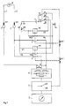
- FIGS. 3 to 6 A purely mechanical coupling between a measuring range switch S and an input circuit switch 9 is shown in FIGS. 3 to 6.
- the two switches are arranged in close spatial proximity to one another, in such a way that the labeling on the control button for the measured variables A to C can be brought into a corresponding position.
- An arrow 13 applied between the two control buttons on the cover plate 11 of the multimeter serves as a reference mark. Both control buttons are thus to be brought into a switch position in which the arrow 13 points to the same measured variable.
- both switches are set to measurand A.
- the three measured variables A to C each have several measuring ranges assigned.
- the coupling between the two switches should act in such a way that the input circuit switch can only be switched on if the arrow 13 points to the same measured variable in both switches. Switching the measuring range switch S between different measuring ranges of the same measured variable A / B or C should, however, be possible despite locking.
- the input circuit switch 9 is constructed as a rotary-pressure switch which has a rotary-pressure element 9a, which must first be brought into a switch position by rotation, in which an input circuit of the multimeter is preselected, which is used to receive the measured variable now located at arrow 13 , in this case the measurand A, is suitable.
- the preselected input circuit is only switched on when the rotary pressure element 9a can be brought into its switched-on position by pressure.
- the first locking element 9c designed as a locking pin
- its position relative to the switch element 10 of the measuring range switch S changes with each rotation of the rotary pressure element 9a to set a different measured variable A to C.
- the second Locking elements 10c in the switch element 10 of the measuring range switch locking grooves are now positioned in such a way that the locking pin 9c can only penetrate into them when both switches have been set to the same measured variable A to C.
- the structure described with two separate switches has the advantage that the possibly large currents in certain input circuits do not have to be switched using the measuring range switch. It is easier to design an input circuit switch with relatively few contacts so that it can handle large currents. In addition, there is no danger to the input circuit switch when switching, since the circuit is always interrupted before switching. Furthermore, the user is forced to pay more attention if he has to put two switches in the correct position and he should make at least two errors when setting the switches, namely, set the same wrong measured variable for both switches before an error occurs.
- FIGS. 1, 2 and 7 show electrical circuits in which the protective function is largely achieved by electrical or electromechanical components.
- the mechanical components required for locking the measuring range switch can, as far as the coding of the different measuring ranges is concerned, correspond to the principle shown in FIG. 4.
- the basic circuit diagram shown in Fig. 1 shows a measurement object Q, e.g. a voltage source, which is connected via the measuring lines L1, L2 and connectors ST1, ST2 to input terminals 1, 2 of the multimeter.
- the multimeter has two input circuits a, b with one for both common input connection 1 and specific input connections 2a, 2b assigned to the respective input circuits.
- the different structure of the input circuits a, b is to be illustrated by the measuring range network N, which e.g. can consist of voltage divider resistors for voltage switching or shunts for current switching, and in which the switching is carried out by a measuring range switch S.
- the correspondingly adapted measuring signal then arrives at a measuring system Z, which is used for measurement and display.
- FIG. 2 essentially corresponds to that in FIG. 1 as far as the multimeter structure is concerned, but differs in that instead of several specific input connections 2a, 2b, common input connections 1,2 are provided for all input circuits a, b, so that there is no need to reconnect measuring lines L1, L2.
- an input circuit switch 8 was inserted into the circuit, which can be switched over from a zero position 0 to a measured variable A or B and thus to the input circuits a, b.
- An auxiliary circuit switch HS5 belonging to the input circuit switch 8 or mechanically coupled to it is also switched over from a zero position 0 to a switching position assigned to the measured variable A or B. Together with a magnetic actuator M3 connected in series, a voltage source U and a switching path S1 of the measuring range switch S, it is located in an auxiliary circuit H5.
- the measuring range switch S allows switching between the measured variables A and B on the one hand and between different measuring ranges A1, A2, A3 of the measured variable A and B1, B2 of the measured variable B.
- the position of the switching path S1 which is dependent on the position of the measuring range switch S is with the auxiliary circuit switch HS5 connected in such a way that the magnetic actuator M3 and the lock Ar3 which is dependent on it are activated as soon as the auxiliary circuit switch S5 is switched to a different measurement variable than the measurement variable specified by the measurement range switch S.
- the auxiliary circuit switch HS5 is designed so that it leads the input circuit switch 8 during the switching process and when the switch to an incorrect measured variable the lock Ar3 is still effective in such a way that it prevents the input circuit switch from switching to an incorrect measured variable.
- the measured variable A set on the measuring range switch S corresponds to the measured variable set on the input circuit switch 8. If, however, an attempt is made to switch the input circuit switch 8 to the measured variable B, then the magnetic adjuster M3 and thus the locking device Ar3 would be activated via the leading auxiliary circuit switch HS 5 in such a way that the input circuit switch 8 would have to be switched back to the zero position 0.
- the described mode of operation of the circuit ensures that after specifying a measured variable by the measuring range switch S, only the input circuit a, b can be switched on, to which the same measured variable is assigned. In addition, however, it should be ensured that when the input circuit switch 8 is switched on and the input circuit a or b is closed, the measuring range switch S cannot be switched over to another measured variable.
- This can be achieved with the aid of a second switching path of the auxiliary circuit switch HS5, which, like its first switching path, has a zero position 0, from which one can switch to one of the measured variables A, B.
- a further magnetic actuator M5 is controlled via this second switching path with the aid of the voltage source U of the auxiliary circuit H5.
- a further magnetic actuator M6 is provided, which monitors the measurement signal U e with the aid of an amplifier V and, when it is omitted, resets the input circuit switch 8 to its zero position 0.
- FIG. 1 is a multimeter with several input connections 1, 2a, 2b.
- the two circuit diagrams according to FIGS. 1 and 2 largely agree, which is also illustrated by the same reference numerals.
- the protective circuit is concerned, differences result from the fact that, according to FIG. 1, the input circuits a, b are interrupted or enabled by controlled input circuit switches 6, 7.
- the input circuit switches are actuated again in dependence on the switching position of the measuring range switch S in such a way that only the input circuit switch 6,7 is switched on, which lies in an input circuit a, b to which the measured variable set on the measuring range switch S corresponds.
- This is achieved with two switching paths S2, S3 belonging to the measuring range switch S, which together with a magnetic actuator M1, M2 each lie in an auxiliary circuit H1, H2 and serve to control the respective input circuit switch 6,7.
- the contactors K1, K2 are integrated into the input connections 2a, 2b in such a way that they only close when a plug ST2 is inserted, for example by the connector ST2 meets an insulating cam of the contactor K1, K2, displacing it so far that the contact closes.
- the magnetic actuator M1 can only switch on the input circuit switch 6 if the auxiliary circuit H1 activating it is closed by the contactor K1 when contacting the input connection 2a and the switching path S3 is like the measuring range switch S in one of the measured variables A is in the appropriate position. This ensures that an input current can only flow in an input circuit a, b which is provided for the measurement variable specified at the measuring range switch S.
- auxiliary circuits H3, H4 are therefore constructed in such a way that the signal generator Su is activated whenever an input connection 2a, 2b is contacted, to which a measured variable is assigned which does not correspond to the measured variable set at the measuring range switch S. This prompts the user to change plug S2.
- Another danger is that when the measuring line L2 is correctly connected and the input circuit switch 6, 7 is accordingly closed, the measuring range switch S is consciously or accidentally switched to another measured variable.
- the safety measures described above would take effect, ie the signal transmitter Su would be activated and the input circuit switch of the input circuit concerned would be opened, but the latter is undesirable, at least as long as a high current flows in the input circuit, for example, since in this case the interruption of the circuit contacts the Can endanger input circuit switch.
- a locking device Ar1 assigned to the magnetic actuator M1 and a locking device Ar2 assigned to the magnetic actuator M2 are provided.
- the two detents Ar1 and Ar2 could also be combined, since they both act on the measuring range switch S and lock it as long as one of the two input circuit switches 6, 7 is switched on. This means that the measuring range switch S can only be switched over if the plug ST2 is removed from the currently contacted input connection 2a, 2b to be plugged into another input connection. This ensures that the input circuit switch 6,7 only opens when the input circuit is de-energized.
- the users of multimeters often find it difficult to move the measuring line L2 into another input connection when the measured variable changes. They usually prefer switchers that save them from having to switch.
- the construction of a corresponding circuit analogous to the circuit of FIG. 1 is possible without difficulty.
- the two input connections 2a, 2b have been replaced by a common input connection 2, which is readily permissible since the input circuit switches 6, 7 allow the input circuits a, b to be switched on separately.
- the pressure exerted on the user by the circuit according to FIG. 1, by paying attention to the correct measured variable A, B both when actuating the measuring range switch S and when contacting the measuring line L2, can also be carried out in a corresponding manner with an auxiliary switch SA can be achieved. This takes the place of the contactors K1, K2 according to FIG. 3 and, like the measuring range switch S, must be in a switch position assigned to a specific measured variable A, B.
Description
Die Erfindung betrifft ein Multimeter der im Oberbegriff des Anspruches 1 genannten Art.The invention relates to a multimeter of the type mentioned in the preamble of
Wegen ihrer vielseitigen Anwendbarkeit erfreuen sich Multimeter in Laboratorien und Werkstätten, aber auch bei Bastlern großer Beliebtheit. Je nach Ausstattung des Multimeters kann eine Vielzahl von Meßgrößen, wie Spannungen, Ströme, Widerstände, Pegel und Frequenzen, um nur einige zu nennen, mit einem einzigen Gerät gemessen werden. Das bedeutet jedoch, daß die Meßschaltungen, die zur Erfassung der verschiedenen Meßgrößen benötigt werden, sich zum Teil erheblich unterscheiden, so daß für die unterschiedlichen Meßgrößen auch unterschiedliche Eingangskreise des Multimeters zur Verfügung stehen müssen.Because of their versatility, multimeters are very popular in laboratories and workshops, but also among hobbyists. Depending on the equipment of the multimeter, a large number of measured variables, such as voltages, currents, resistances, levels and frequencies, to name just a few, can be measured with a single device. However, this means that the measuring circuits that are required to record the various measured variables differ considerably in some cases, so that different input circuits of the multimeter must also be available for the different measured variables.
Es ist wichtig, daß vor jeder Messung der richtige, der zu untersuchenden Meßgröße zugeordnete Eingangskreis angeschlossen wird. Soll z. B. die Netzspannung gemessen werden und bleibt versehentlich der Eingangskreis eingeschaltet, der zur Messung von Strömen vorgesehen ist, so kann das für das Multimeter, bisweilen sogar für den Bedienenden, schwerwiegende Folgen haben, wenn die Netzsicherung nicht schnell genug abschaltet. Die im Multimeter vorgesehene Gerätesicherung reicht in aller Regel nicht aus, um das Multimeter von einer energiereichen Spannungsgquelle zu trennen, da der beim Öffnen des Stromkreises auftretende Lichtbogen die Gerätesicherung überbrücken kann.It is important that the correct input circuit assigned to the measured variable to be examined is connected before each measurement. Should z. If the mains voltage is measured and the input circuit that is intended for measuring currents is accidentally switched on, this can have serious consequences for the multimeter, sometimes even for the operator, if the mains fuse does not switch off quickly enough. The device fuse provided in the multimeter is usually not sufficient to disconnect the multimeter from a high-energy voltage source, since the arc occurring when the circuit is opened can bypass the device fuse.
Ähnliche Probleme und Gefahren können auch bei anderen Kombinationen, bei denen eine Meßgröße auf einen falschen Eingangskreis trifft, für das Meßobjekt, das Multimeter und den Bedienenden entstehen. Doch selbst dann, wenn aus einem Bedienungsfehler keine unmittelbare Gefahr resultiert, kann es immer noch zu einer mittelbaren Gefährdung kommen, wenn z.B. die Anzeige des Multimeters das Fehlen einer zu prüfenden Spannung vortäuscht, weil ein Eingangskreis angeschlossen wurde, der gerade außer Betrieb, also nicht mit dem Meßsystem verbunden war. Durch die vorgetäuschte Spannungsfreiheit wird der Bedienende bisweilen zu ihn gefährdenden Handlungen verleitet.Similar problems and dangers can also arise with other combinations, in which a measured variable meets the wrong input circuit, for the test object, the multimeter and the operator. But even if an operating error does not result in an immediate danger, there can still be an indirect danger if, for example the display of the multimeter simulates the absence of a voltage to be tested because an input circuit was connected that was just out of operation, i.e. not connected to the measuring system. Due to the feigned lack of voltage, the operator is sometimes tempted to take actions that endanger him.
Worauf zu achten ist, damit es bei einem Multimeter nicht zu derartigen Fehlbedienungen kommt, hängt vom Aufbau dieses Gerätes ab. Bei vielen Multimetern besitzen die verschiedenen Eingangskreise einen allen Eingangskreisen gemeinsamen ersten Eingangsanschluß und einen eigenen dem jeweiligen Meßkreis zugeordneten mit der zugehörigen Meßgröße korrespondierenden zweiten Eingangsanschluß. In der Regel gehören zu jeder Meßgröße wiederum mehrere Meßbereiche z.B. zur Meßgröße "Spannung" die Meßbereiche 1, 3, 10, 30V usw. Der Eingangskreis besitzt in diesem Fall einen Spannungsteiler, an dem alle Spannungen auf Werte herabgeteilt oder auch durch Verstärkung erhöht werden, damit an das Meßsystem angepaßte Werte zur Verfügung stehen.What needs to be taken into account so that such a malfunction does not occur with a multimeter depends on the structure of this device. In the case of many multimeters, the various input circuits have a first input connection common to all input circuits and a second input connection assigned to the respective measuring circuit and corresponding to the associated measured variable. As a rule, belong to every measured variable again several measuring ranges, for example the measuring range "voltage" the
Für das Umschalten des Spannungsteilers auf einen gewünschten Spannungsmeßbereich bzw. das Umschalten von Shunts auf einen gewünschten Strommeßbereich verwendet man einen Meßbereichsschalter. Bei der Bedienung des Meßgerätes muß man also dafür sorgen, daß der Meßbereichsschalter auf die Meßgröße gestellt wird, die gemessen werden soll. Gleichzeitig ist aber darauf zu achten, daß eingangsseitig am Multimeter die Meßleitungen mit den richtigen Eingangsanschlüssen und dadurch mit dem richtigen Eingangskreis verbunden werden.A measuring range switch is used to switch the voltage divider to a desired voltage measuring range or to switch shunts to a desired current measuring range. When operating the measuring device you have to make sure that the measuring range switch is set to the measurand to be measured. At the same time, however, it must be ensured that the measuring leads are connected to the correct input connections on the multimeter on the input side and thus to the correct input circuit.
Es liegt auf der Hand, daß bei weniger konzentriertem Arbeiten, besonders auch durch Nichtfachleute, einer der beiden Bedienhandgriffe vergessen werden kann und dann entweder der falsche Eingangskreis angeschlossen, oder ein falscher Meßbereich eingeschaltet wird.It is obvious that in less concentrated work, especially by non-specialists, one of the two operating handles can be forgotten and then either the wrong input circuit is connected or an incorrect measuring range is switched on.
Selbstverständlich hat man versucht mit zusätzlichen Sicherungsmaßnahmen die Gefahren einer Fehlbedienung in Grenzen zu halten. Die verwendeten Schutzschaltungen arbeiten mit passiven und aktiven Schaltern, Relaisschaltern, gesteuerten Halbleiterschaltern, mit Transistoren und Thyristoren sowie Schmelzsicherungen besonderer Bauart. Trotz des teilweise recht hohen Aufwandes gelingt es mit bisherigen Techniken jedoch keineswegs immer, leistungsstarke Spannungsquellen innerhalb des kleinen, bei modernen Multimetern zur Verfügung stehenden Raumes im Fehlerfall sicher abzuschalten. Eine Verminderung der Gefahren läßt sich somit nur erzielen, wenn die Fehlbedienung weitgehend ausgeschlossen wird.Of course, attempts have been made to limit the dangers of incorrect operation with additional safety measures. The protective circuits used work with passive and active switches, relay switches, controlled semiconductor switches, with transistors and thyristors as well as fuses of a special design. Despite the sometimes very high outlay, previous techniques do not always succeed in safely switching off powerful voltage sources within the small space available in modern multimeters in the event of a fault. A reduction in the dangers can only be achieved if the incorrect operation is largely excluded.
Es wurde versucht diese Aufgabe dadurch zu lösen, daß man das Umstecken der Meßleitungen durch Umschalten der Eingangskreise ersetzte. Hierdurch wurde zwar die Bedienung des Meßgerätes etwas erleichtert, aber das Problem nicht beseitigt. So kann das Umschalten der Eingangskreise entweder durch einer zusätzlichen Eingangskreisschalter geschehen oder durch den Meßbereichsschalter zusätzlich übernommen werden. Ein zusätzlicher Eingangskreisschalter verlagert das Problem lediglich auf ein anderes Bauteil, da nun mit gleicher Aufmerksamkeit darauf geachtet werden muß, daß sowohl der Eingangskreisschalter als auch der Meßbereichsschalter auf die zu untersuchende Meßgröße gestellt wurden. Demgegenüber bedeutet eine Zusammenfassung aller Schaltfunktionen am Meßbereichsschalter, daß dieser in der Lage sein muß außer sehr kleinen auch große Leistungen zu schalten, was wiederum eine erhebliche Verteuerung dieses Bauelements zu Folge hat. Außerdem ist zu bedenken, das die hierdurch erreichte Verminderung der Zahl der Bedienelemente nicht zwangsläufig die Bedienung wesentlich sicherer macht, denn auch ein einziger Schalter kann immer noch in eine falsche Schaltstellung gebracht werden, was dann zwangsläufig zum Anschluß auch eines falschen Eingangskreises mit entsprechenden Folgen führt. Insofern kann der Zwang auf die richtige Stellung von zwei Bedienelementen achten zu müssen, zu einer erhöhten Aufmerksamkeit führen.An attempt was made to solve this problem by replacing the plugging in of the measuring lines by switching the input circuits. As a result, the operation of the measuring device was made somewhat easier, but the problem was not eliminated. The switching of the input circuits can either be done by an additional input circuit switch or can also be carried out by the measuring range switch. An additional input circuit switch only shifts the problem to another component, since care must now be taken to ensure that both the input circuit switch and the measuring range switch have been set to the measured variable to be examined. In contrast, a summary of all switching functions on the measuring range switch means that the latter must be able to switch not only very small but also large powers, which in turn results in a considerable increase in the cost of this component. It should also be borne in mind that the reduction in the number of control elements achieved in this way does not necessarily make operation much safer, because even a single switch can still be brought into the wrong switch position, which inevitably leads to the connection of an incorrect input circuit with corresponding consequences . In this respect, the need to pay attention to the correct position of two controls can lead to increased attention.
Bekannt ist in diesem Zusammenhang aus "Funkschau 1970, Heft 20, Seite 2023", ein Multimeter mit dem Namen "NORMATEST", das zwei Schalter besitzt, die zur Messung im Meßbereich 12mV beide auf diesen Meßbereich gestellt werden müssen, damit ein Strom zum Meßwerk des Multimeters fließen kann. Die nicht miteinander gekoppelten Schalter können jedoch unabhängig voneinander in jede ihrer Schaltstellungen gebracht werden, so daß kein Schutz für die Eingangskreise des Multimeters mit den Vor- und Nebenwiderständen erreicht wird und daß es außerdem zu einer Unterbrechung des Meßstromkreises und einer daraus resultierenden Fehlmessung kommen kann.In this context it is known from "Funkschau 1970, Issue 20, page 2023", a multimeter with the name "NORMATEST", which has two switches, both of which must be set to this measuring range for measuring in the measuring range 12mV, so that a current to the measuring mechanism of the multimeter can flow. The switches that are not coupled to one another can, however, be brought into each of their switch positions independently of one another, so that no protection for the input circuits of the multimeter with the series and shunt resistors is achieved and that there can also be an interruption in the measuring circuit and the resultant incorrect measurement.
Aufgabe der Erfindung ist es, ein Multimeter nach dem Oberbegriff des Anspruchs 1 zu schaffen, das mit einem Meßbereichsschalter auskommt, der nur sehr kleine Leistungen zur Weitergabe an das Meßsystem schalten muß, und das Risiko, daß es zu einer Fehlbedienung des Meßgerätes kommt, vermindert.The object of the invention is to provide a multimeter according to the preamble of
Diese Aufgabe wird durch die im Anspruch 1 gekennzeichneten Merkmale gelöst. Zweckmäßige Ausgestaltungen und Weiterbildungen des Erfindungsgegenstandes sind in den Unteransprüchen genannt.This object is achieved by the features characterized in
Erfindungsgemäß soll das Multimeter mindestens einen Eingangskreisschalter besitzen, der unabhängig von der mit Hilfe des Meßbereichsschalters getroffenen Meßgrößenvorgabe zusätzlich ein- oder umgeschaltet werden muß, damit das angelegte Meßsignal in den der vorgegebenen Meßgröße zugehörigen Eingangskreis gelangt. Dies scheint der Lösung, daß eine Kopplung zwischen dem Eingangskreisschalter und dem Meßbereichsschalter bestehen soll, zu widersprechen. Entscheidend ist jedoch, daß die Kopplungsvorrichtung nicht starr ist, sondern nur soweit gehen darf, daß sichergestellt ist, daß der jeweilige Eingangskreis nur eingeschaltet werden kann, wenn die ihm zugeordnete Meßgröße mit der am Meßbereichsschalter vorgegebenen Meßgröße übereinstimmt. Obwohl es sich also um eine genau definierte Kopplung handelt, ermöglicht diese ein separtes Ein- oder Umschalten des Eingangskreisschalters einerseits und des Meßbereichsschalters andererseits. Der Benutzer des Multimeters wird hierdurch zur erhöhten Aufmerksamkeit gezwungen, da er zwei Schalter in eine Schaltstellung bringen muß, die der von ihm gewünschten Meßgröße entsprechen. Nur wenn beide Schalter auf die falsche Meßgröße gestellt werden und noch dazu auf die gleiche falsche Meßgröße, kann es zu einer Gefährdung des Multimeters kommen. Die Wahrscheinlichkeit hierfür ist jedoch wesentlich geringer, als bei üblichen Multimetern, da der Benutzer nunmehr zwei Fehler, ja sogar zwei gleiche Fehler machen müßte, was relativ unwahrscheinlich ist. Solange er nur einen der beiden Schalter falsch einstellt, besteht durch die Kopplung der beiden Schalter keine Übereinstimmung und der eingestellte Eingangskreis des Multimeters wird nicht eingeschaltet.According to the invention, the multimeter should have at least one input circuit switch, which must also be switched on or over independently of the measurement variable setting made with the aid of the measurement range switch, so that the applied measurement signal reaches the input circuit associated with the specified measurement variable. This seems to contradict the solution that there should be a coupling between the input circuit switch and the measuring range switch. It is crucial, however, that the coupling device is not rigid, but may only go so far as to ensure that the respective input circuit can only be switched on when the measured variable assigned to it corresponds to the measured variable specified at the measuring range switch. Although it is a precisely defined coupling, this enables the input circuit switch on the one hand and the measuring range switch on the other to be switched on or off separately. The user of the multimeter is thereby forced to pay more attention, since he has to bring two switches into a switch position that correspond to the measurement quantity he wants. The multimeter can only be endangered if both switches are set to the wrong measured variable and the same wrong measured variable. However, the probability of this is much lower than with conventional multimeters, since the user would now have to make two errors, even two identical errors, which is relatively unlikely. As long as he incorrectly sets one of the two switches, there is no match due to the coupling of the two switches and the set input circuit of the multimeter is not switched on.
Ziel einer Weiterbildung des Erfindungsgegenstandes ist, zu verhindern, daß nach einer richtigen Wahl des Meßbereiches durch den Meßbereichsschalter und den Eingangskreisschalter bewußt oder unbewußt der Meßbereichsschalter umgeschaltet wird, und diese Fehlbedienung zu einer Gefährdung des Multimeters führt. Es ist deshalb weiterhin eine Arretiervorrichtung vorgesehen, die ein Umschalten auf eine andere Meßgröße nur nach Lösen der Arretierung ermöglicht.The aim of a development of the subject matter of the invention is to prevent the measuring range switch and the input circuit switch from being consciously or unconsciously switched over after a correct selection of the measuring range, and this incorrect operation leads to a risk to the multimeter. A locking device is therefore also provided, which enables switching to a different measured variable only after the locking has been released.
Baut man die Arretiervorrichtung mit mechanischen Bauelementen auf, so wird man ein erstes Arretierelement vorzugsweise als Arretierzapfen ausbilden, so daß dieses dann in ein zweites Arretierelement, vorzugsweise eine Arretiernut eingreifen kann, wobei letztere an einem beweglichen, das Umschalten ermöglichenden Teil des jeweiligen Schalters ausgebildet ist und so ein Umschalten auf eine unzulässige Meßgröße verhindert. Bei einem von Hand zu betätigenden Eingangskreisschalter kann man diesen im Aktionsbereich eines beweglichen Teiles des Meßbereichsschalters, vorzugsweise eines zu diesem gehörigen Schaltrades montieren, und die beiden Schalter so miteinander koppeln, daß das erste Arretierelement am beweglichen Teil des Eingangskreisschalters ausgebildet ist, und dieses an einem zweiten an einem beweglichen Teil des Meßbereichsschalters ausgebildeten Arretierelement einen Eingriff findet.If the locking device is built up with mechanical components, a first locking element will preferably be designed as a locking pin, so that it can then engage in a second locking element, preferably a locking groove, the latter being formed on a movable part of the respective switch which enables switching and thus prevents switching to an impermissible measured variable. In the case of an input circuit switch which can be operated by hand, it can be mounted in the action area of a movable part of the measuring range switch, preferably a switching wheel belonging to it, and the two switches can be coupled with one another in such a way that the first locking element is formed on the movable part of the input circuit switch, and this on one second locking element formed on a movable part of the measuring range switch engages.
Um die Unabhängigkeit der beiden Schalter voneinander zu gewährleisten, darf ein solcher Eingriff allerdings nur durch entsprechende Betätigung des Benutzers herbeigeführt werden. Hierzu ist es vorteilhaft, den Eingangskreisschalter als kombinierten Dreh- und Druckschalter zu gestalten, der durch Drehen mindestens zwei unterschiedliche Grundstellungen einnehmen kann, in denen er bei einer Druckbetätigung jeweils einen bestimmten Eingangskreis einschaltet. Das erste Arretierelement kann dabei von der Grundstellung des Eingangskreisschalters aus in verschiedene, der Meßgröße zugeordnete zweite Arretierelemente, vorzugsweise Nuten im beweglichen Teil des Meßbereichsschalters eindringen. Die Arretierung sorgt nunmehr dafür, daß ein Verstellen der Schalter zu einer anderen Meßgröße nur bei ausgeschaltetem Eingangskreisschalter möglich ist.In order to ensure the independence of the two switches from one another, such an intervention may, however, only be brought about by appropriate actuation of the user. For this purpose, it is advantageous to design the input circuit switch as a combined rotary and pressure switch which, by turning, can assume at least two different basic positions, in which it each has a specific input circuit when actuated by pressure switches on. The first locking element can penetrate from the basic position of the input circuit switch into various second locking elements associated with the measured variable, preferably grooves in the movable part of the measuring range switch. The lock now ensures that the switches can only be adjusted to a different measured variable when the input circuit switch is switched off.
Da eine Kopplung zwischen den beiden Schaltern nur solange besteht, solange die Arretierelemente ineinandergreifen, wirken letztere bei dieser Ausführungsform des Eingangskreisschalters auch als Kopplungselemente, so daß bei gelöster Arretierung auch keine Kopplung mehr besteht. Zweckmäßigerweise ist die Lage oder Art der ersten Arretierelemente zur Lage oder Art der zweiten Arretierelemente so codiert, daß ein gegenseitiger Eingriff und damit ein Einschalten des Eingangskreisschalters nur möglich ist, wenn beide Schalter auf die gleiche Meßgröße gestellt sind, bei eingeschaltetem Eingangskreisschalter aber nicht umgeschaltet werden kann. Dies kann man mit mindestens einem als Zapfen ausgebildeten exzentrisch angeordneten ersten Arretierelement erreichen, das für eine beim Drehen des Eingangskreisschalters entsprechend wechselnde Positionierung sorgt und dem als Nuten ausgebildete zweite Arretierelemente so gegenüberstehen, daß nur bei übereinstimmender Stellung der Zapfen in die zugehörige Nut eingreifen kann.Since there is a coupling between the two switches only as long as the locking elements engage, the latter also act as coupling elements in this embodiment of the input circuit switch, so that there is no longer any coupling when the locking is released. The position or type of the first locking elements is expediently coded to the position or type of the second locking elements so that mutual intervention and thus switching on the input circuit switch is only possible if both switches are set to the same measured variable, but are not switched over when the input circuit switch is switched on can. This can be achieved with at least one eccentrically arranged first locking element designed as a pin, which ensures a correspondingly changing positioning when the input circuit switch is rotated and is opposed to the second locking elements designed as grooves such that the pin can only engage in the associated groove if the position of the pin coincides.
Die Kopplungsvorrichtung läßt sich auch mit Hilfe von elektrischen Schaltkreisen aufbauen. So kann man den Meßbereichsschalter mit mindestens einer zusätzlichen Schaltstrecke ausrüsten, über die mindestens ein Hilfskreis geführt ist, derart, daß sich bei eingeschaltetem Hilfskreis eine feste von der Schaltstellung des Meßbereichsschalters abhängige Zuordnung zu einem bestimmten Eingangskreis und damit zu einer bestimmten Meßgröße ergibt. In den Hilfskreis kann man mindestens einen Funktionsgeber einfügen, der bei Betätigung durch Schließen des Hilfsstromkreises aktiviert wird. Es hängt wesentlich von der Art des Funktionsgebers und der Ausgestaltung der Hilfskreise ab, welcher Schutz mit der Schaltung erzielbar ist.The coupling device can also be constructed with the aid of electrical circuits. For example, the measuring range switch can be equipped with at least one additional switching path, through which at least one auxiliary circuit is guided, such that when the auxiliary circuit is switched on, a fixed assignment to a specific one is dependent on the switching position of the measuring range switch Input circuit and thus results in a certain measured variable. At least one function transmitter can be inserted in the auxiliary circuit, which is activated when the auxiliary circuit is closed by actuation. It depends largely on the type of function generator and the design of the auxiliary circuits, which protection can be achieved with the circuit.
Zweckmäßig ist es, jeder Meßgröße einen Hilfskreisschalter zuzuordnen, dessen Schaltstellung mit der Schaltstellung des Eingangskreisschalters fest gekoppelt ist.It is expedient to assign an auxiliary circuit switch to each measured variable, the switch position of which is firmly coupled to the switch position of the input circuit switch.
Mit einem als Umschalter oder Einschalter wirkenden Eingangskreisschalter kann eine Schutzschaltung sowohl für Multimeter mit gemeinsamen Eingangsanschlüssen für alle Eingangskreise als auch für Multimeter mit mehreren den verschiedenen Eingangskreisen spezifischen Eingangsanschlüssen aufgebaut werden. Bei einem Multimeter mit mehreren Eingangsanschlüssen ist es vorteilhaft, in mindestens einen Eingangsanschluß einen Kontaktgeber zu integrieren, dessen Kontaktstrecke in mindestens einem Hilfskreis liegt. Der Kontaktgeber ist dabei so auszuführen, daß er beim Anschließen einer Meßleitung kontaktiert und dadurch den jeweiligen Hilfskreis schließt. Wird ein solcher Hilfskreis auch in Abhängigkeit von der Stellung des Meßbereichsschalters ein- oder ausgeschaltet, und aktiviert er einen Funktionsgeber, der in diesem Fall ein Signalgeber sein kann, so ist es möglich, ein optisches oder akustisches Warnsignal abzugeben, wenn mit den Meßleitungen ein Eingangskreis verbunden wird, dem eine andere Meßgröße als die am Meßbereichsschalter eingestellte Meßgröße zugeordnet ist. Ein gegebenenfalls in einem zweiten Hilfskreis liegender zweiter Funktionsgeber kann als Magnetsteller ausgebildet sein und zur Betätigung des Eingangskreisschalters dienen.With an input circuit switch acting as a changeover switch or a switch, a protective circuit can be constructed both for multimeters with common input connections for all input circuits and for multimeters with several input connections specific to the different input circuits. In the case of a multimeter with several input connections, it is advantageous to integrate a contactor into at least one input connection, the contact path of which lies in at least one auxiliary circuit. The contactor must be designed so that it contacts when connecting a measuring line and thereby closes the respective auxiliary circuit. If such an auxiliary circuit is also switched on or off depending on the position of the measuring range switch, and if it activates a function generator, which in this case can be a signal generator, it is possible to emit an optical or acoustic warning signal if an input circuit is connected to the measuring lines is connected to which a different measured variable is assigned than the measured variable set at the measuring range switch. A second function transmitter, which may be located in a second auxiliary circuit, can be designed as a magnetic actuator and can be used to actuate the input circuit switch.
Eine Schaltkreiskopplung über bestimmte Schaltstrecken des Meßbereichsschalters sorgt dafür, daß mindestens ein Eingangskreis nur eingeschaltet werden kann, wenn die diesem Eingangskreis zugeordnete Meßgröße mit der am Meßbereichsschalter eingestellten Meßgröße übereinstimmt.A circuit coupling over certain switching paths of the measuring range switch ensures that at least one input circuit can only be switched on if the measured variable assigned to this input circuit matches the measured variable set on the measuring range switch.
Es ist vorteilhaft, den als Magnetsteller wirkenden zweiten Funktionsgeber mit einem bistabilen Schaltverhalten auszustatten, derart, daß durch Ein- und Ausschaltimpulse ein Stellungswechsel herbeiführbar ist. Bei entsprechendem mechanischem Aufbau kann der Magnetsteller außer dem Eingangskreisschalter und einem Hilfskreisschalter auch ein Arretierelement betätigen. Die Auslösung des Arretierelementes kann selbstverständlich auch durch einen zweiten Magnetsteller erfolgen. Wesentlich ist, daß das Arretierelement nur aktiviert wird, wenn die am Meßbereichsschalter eingeschaltete Meßgröße mit der dem Eingangsanschluß zugeordneten Meßgröße übereinstimmt, also der Eingangskreisschalter mit dem zugeordneten Anschluß korreliert.It is advantageous to equip the second function transmitter, which acts as a magnetic actuator, with a bistable switching behavior, such that a change in position can be brought about by switching on and off pulses. With the appropriate mechanical structure, the magnetic actuator can also operate a locking element in addition to the input circuit switch and an auxiliary circuit switch. The locking element can of course also be triggered by a second magnetic actuator. It is essential that the locking element is only activated if the measured variable switched on at the measuring range switch matches the measured variable assigned to the input connection, that is to say the input circuit switch correlates with the assigned connection.
Ausführungsbeispiele der Erfindung sind in den Zeichnungen dargestellt und werden im folgenden näher beschrieben.Embodiments of the invention are shown in the drawings and are described in more detail below.
Es zeigen:
- Fig. 1
- Prinzipschaltbild zur Sperrung bestimmter Eingangskreise bei einem Multimeter mit mehreren Eingangsanschlüssen und gesteuerten Eingangskreisschaltern,
- Fig. 2
- Prinzipschaltbild zur Sperrung bestimmter Eingangskreise bei einem Multimeter mit zwei gemeinsamen Eingangsanschlüssen und handbetätigbarem Eingangskreisschalter,
- Fig. 3
- Meßbereichsschalter und handbetätigter Eingangskreisschalter in Draufsicht auf die Deckplatte des Multimeters,
- Fig. 4
- mechanische Kopplung zwischen Meßbereichs- und Eingangskreisschalter in Draufsicht,
- Fig. 5
- mechanische Kopplung zwischen Meßbereichs- und Eingangskreisschalter in Seitenansicht in entkoppelter Stellung,
- Fig. 6
- mechanische Kopplung zwischen Meßbereichs- und Eingangskreisschalter in Seitenansicht in gekoppelter Stellung,
- Fig. 7
- Prinzipschaltbild zur Sperrung bestimmter Eingangskreise bei einem Multimeter mit zwei gemeinsamen Eingangsanschlüssen und gesteuerten Eingangskreisschaltern.
- Fig. 1
- Block diagram for blocking certain input circuits in a multimeter with multiple input connections and controlled input circuit switches,
- Fig. 2
- Block diagram for blocking certain input circuits with a multimeter with two common input connections and manually operated input circuit switch,
- Fig. 3
- Measuring range switch and manually operated input circuit switch in top view of the cover plate of the multimeter,
- Fig. 4
- mechanical coupling between measuring range and input circuit switch in top view,
- Fig. 5
- mechanical coupling between measuring range and input circuit switch in side view in decoupled position,
- Fig. 6
- mechanical coupling between measuring range and input circuit switch in side view in coupled position,
- Fig. 7
- Block diagram for blocking certain input circuits in a multimeter with two common input connections and controlled input circuit switches.
Eine rein mechanische Kopplung zwischen einem Meßbereichsschalter S und einem Eingangskreisschalter 9 ist in den Figuren 3 bis 6 dargestellt. Wie Fig. 3 zeigt sind die beiden Schalter in unmittelbarer räumlicher Nähe zueinander angeordnet und zwar derart, daß die auf ihrem Bedienknopf aufgebrachte Beschriftung für die Meßgrößen A bis C in eine zueinander korrespondierende Stellung gebracht werden kann. Als Bezugsmarke dient ein zwischen den beiden Bedienknöpfen auf der Deckplatte 11 des Multimeters aufgebrachter Pfeil 13. Beide Bedienknöpfe sind somit in eine Schalterstellung zu bringen, in der der Pfeil 13 auf die gleiche Meßgröße weist. Im vorliegenden Beispiel sind beide Schalter auf die Meßgröße A eingestellt. Beim Meßbereichsschalter S sind den drei Meßgrößen A bis C noch jeweils mehrere Meßbereiche zugeordnet. Die Kopplung zwischen den beiden Schaltern soll so wirken, daß der Eingangskreisschalter nur eingeschaltet werden kann, wenn der Pfeil 13 bei beiden Schaltern auf die gleiche Meßgröße weist. Ein Umschalten des Meßbereichsschalters S zwischen verschiedenen Meßbereichen der gleichen Meßgröße A/B oder C soll jedoch trotz Arretierung möglich sein.A purely mechanical coupling between a measuring range switch S and an
Die Fig. 4 bis 6 verdeutlichen eine Möglichkeit zur Realisierung der Kopplung. Ein zum Meßbereichsschalter S gehöriges und von diesem angetriebenes radartiges Schalterelement 10 ist mit einem so großen Durchmesser versehen, daß es bis in den Aktionsbereich des Eingangskreisschalters 9 reicht. Der Eingangskreisschalter 9 ist als Dreh-Druck-Schalter aufgebaut, der ein Dreh-Druckelement 9a besitzt, das zunächst durch Drehung in eine Schaltstellung gebracht werden muß, in der ein Eingangskreis des Multimeters vorgewählt wird, der zur Aufnahme der nunmehr am Pfeil 13 liegenden Meßgröße, in diesem Fall die Meßgröße A, geeignet ist. Ein Einschalten des vorgewählten Eingangskreises wird jedoch erst herbeigeführt, wenn es gelingt, das Dreh-Druckelement 9a durch Druck in seine Einschaltstellung zu bringen. Dies ist jedoch nur erreichbar, wenn ein mit dem Dreh-Druckelement 9a verbundenes scheibenartiges Kopplungselement 9b, das mit einem exzentrisch an ihm befestigten ersten Arretierelement 9c versehen ist, in ein zweites als Arretiernut ausgebildetes Arretierelement 10c des Schalterelements 10 eingreifen kann.4 to 6 illustrate one possibility of realizing the coupling. A wheel-
Durch die exzentrische Anordnung des als Arretierzapfen ausgebildeten ersten Arretierelementes 9c ändert sich dessen Lage zum Schalterelement 10 des Meßbereichsschalters S mit jeder Drehung des Drehdruckelementes 9a zum Einstellen einer anderen Meßgröße A bis C. Die als zweites Arretierelement 10c im Schalterelement 10 des Meßbereichsschalters ausgebildeten Arretiernuten sind nun jeweils so positioniert, daß der Arretierzapfen 9c nur dann in sie eindringen kann, wenn beide Schalter auf die gleiche Meßgröße A bis C gestellt wurden.Due to the eccentric arrangement of the
Da die Arretierung lediglich ein Umschalten des Meßbereichsschalters zwischen den verschiedenen Meßgrößen A bis C bei eingeschaltetem Eingangskreisschalter 9 verhindern soll, ist innerhalb des Arretierungsbereichs 10a einer Meßgröße ein Umschalten zwischen verschiedenen Meßbereichen dieser Meßgröße möglich.Since the locking is only intended to prevent the measuring range switch from switching between the various measured variables A to C when the
Der beschriebene Aufbau mit zwei getrennten Schaltern hat den Vorteil, daß die gegebenenfalls großen Ströme in bestimmten Eingangskreisen nicht mit Hilfe des Meßbereichsschalters geschaltet werden müssen. Es ist einfacher einen mit relativ wenigen Kontakten versehenen Eingangskreisschalter so zu gestalten, daß er auch große Ströme beherrscht. Darüberhinaus ist eine Gefährdung des Eingangskreisschalters beim Umschalten nicht möglich, da vor dem Umschalten immer erst der Stromkreis unterbrochen wird. Weiterhin ist der Benutzer zu erhöhter Aufmerksamkeit gezwungen, wenn er jeweils zwei Schalter in die richtige Stellung bringen muß und er müßte bei der Einstellung der Schalter mindestens zwei Fehler machen, nämlich bei beiden Schaltern die gleiche falsche Meßgröße einstellen, bevor es zu einem Fehlerfall kommt.The structure described with two separate switches has the advantage that the possibly large currents in certain input circuits do not have to be switched using the measuring range switch. It is easier to design an input circuit switch with relatively few contacts so that it can handle large currents. In addition, there is no danger to the input circuit switch when switching, since the circuit is always interrupted before switching. Furthermore, the user is forced to pay more attention if he has to put two switches in the correct position and he should make at least two errors when setting the switches, namely, set the same wrong measured variable for both switches before an error occurs.
Die weiteren Beispiele zum Aufbau einer Schutzvorrichtung nach den Figuren 1,2 und 7 zeigen elektrische Schaltungen, bei denen die Schutzfunktion weitgehend durch elektrische bzw. elektromechanische Bauelemente erreicht wird. Die zur Arretierung des Meßbereichsschalters benötigten mechanischen Bauelemente können, soweit es die Codierung der verschiedenen Meßbereiche betrifft, dem in Fig. 4 dargestellten Prinzip entsprechen.The further examples for the construction of a protective device according to FIGS. 1, 2 and 7 show electrical circuits in which the protective function is largely achieved by electrical or electromechanical components. The mechanical components required for locking the measuring range switch can, as far as the coding of the different measuring ranges is concerned, correspond to the principle shown in FIG. 4.
Das in Fig. 1 dargestellte Prinzipschaltbild zeigt ein Meßobjekt Q, z.B. eine Spannungsquelle, das über die Meßleitungen L1, L2 und Stecker ST1,ST2 mit Eingangsanschlüssen 1,2 des Multimeters verbunden ist. Das Multimeter besitzt zwei Eingangskreise a,b mit einem für beide gemeinsamen Eingangsanschluß 1 und spezifischen, den jeweiligen Eingangskreisen zugeordneten Eingangsanschlüssen 2a,2b. Der unterschiedliche Aufbau der Eingangskreise a, b soll durch das Meßbereichsnetzwerk N verdeutlicht werden, das z.B. aus Spannungsteilerwiderständen zur Spannungsumschaltung oder Shunts zur Stromumschaltung bestehen kann, und bei dem die Umschaltung durch einen Meßbereichsschalter S erfolgt. Das entsprechend angepaßte Meßsignal gelangt anschließend zu einem Meßsystem Z, das zur Messung und Anzeige dient.The basic circuit diagram shown in Fig. 1 shows a measurement object Q, e.g. a voltage source, which is connected via the measuring lines L1, L2 and connectors ST1, ST2 to input
Zwischen den Eingangsanschlüssen 2a,2b, denen jeweils die Meßgrößen A,B zugeordnet sind, und der diesen Meßgrößen zugeordneten Schaltstellung des Meßbereichsschalter S besteht ein Zusammenhang derart, daß die Meßleitung L2 unbedingt mit dem richtigen Eingangsanschluß 2a, 2b verbunden werden muß.There is a connection between the
Das in Fig. 2 dargestellte Prinzipschaltbild entspricht soweit es den Multimeteraufbau betrifft, im wesentlichen dem in Fig. 1, unterscheidet sich aber dadurch, daß anstelle mehrerer spezifischer Eingangsanschlüsse 2a,2b für alle Eingangskreise a,b gemeinsame Eingangsanschlüsse 1,2 vorgesehen sind, so daß ein Umstecken von Meßleitungen L1,L2 entfällt. Als Ersatz für das Umstecken wurde ein Eingangskreisschalter 8 in die Schaltung eingefügt, der ausgehend von einer Nullstellung 0 auf eine Meßgröße A oder B und damit auf die Eingangskreise a,b umgeschaltet werden kann.The basic circuit diagram shown in FIG. 2 essentially corresponds to that in FIG. 1 as far as the multimeter structure is concerned, but differs in that instead of several
Ein zum Eingangskreisschalter 8 gehöriger oder mit diesem mechanisch gekoppelter Hilfskreisschalter HS5 wird ebenfalls ausgehend von einer Nullstellung 0 auf eine der Meßgröße A oder B zugeordnete Schaltstellung umgeschaltet. Zusammen mit einem in Reihe geschalteten Magnetsteller M3, einer Spannungsquelle U und einer Schaltstrecke S1 des Meßbereichschalters S liegt er in einem Hilfskreis H5.An auxiliary circuit switch HS5 belonging to the input circuit switch 8 or mechanically coupled to it is also switched over from a zero position 0 to a switching position assigned to the measured variable A or B. Together with a magnetic actuator M3 connected in series, a voltage source U and a switching path S1 of the measuring range switch S, it is located in an auxiliary circuit H5.
Der Meßbereichsschalter S erlaubt ein Umschalten zwischen den Meßgrößen A und B einerseits sowie zwischen verschiedenen Meßbereichen A1,A2,A3 der Meßgröße A und B1,B2 der Meßgröße B. Die von der Stellung des Meßbereichsschalters S abhängige Stellung der Schaltstrecke S1 ist mit dem Hilfskreisschalter HS5 so verbunden, daß der Magnetsteller M3 und die von ihm abhängige Arretierung Ar3 aktiviert wird, sobald der Hilfskreisschalter S5 auf eine andere Meßgroße geschaltet wird als die durch den Meßbereichsschalter S vorgegebene Meßgröße. Der Hilfskreisschalter HS5 ist dabei so ausgelegt, daß er bei dem Schaltvorgang dem Eingangskreisschalter 8 vorauseilt und beim Umschalten auf eine falsche Meßgröße die Arretierung Ar3 noch in einer Weise wirksam wird, daß sie ein Umschalten des Eingangskreisschalters auf eine falsche Meßgröße verhindert.The measuring range switch S allows switching between the measured variables A and B on the one hand and between different measuring ranges A1, A2, A3 of the measured variable A and B1, B2 of the measured variable B. The position of the switching path S1 which is dependent on the position of the measuring range switch S is with the auxiliary circuit switch HS5 connected in such a way that the magnetic actuator M3 and the lock Ar3 which is dependent on it are activated as soon as the auxiliary circuit switch S5 is switched to a different measurement variable than the measurement variable specified by the measurement range switch S. The auxiliary circuit switch HS5 is designed so that it leads the input circuit switch 8 during the switching process and when the switch to an incorrect measured variable the lock Ar3 is still effective in such a way that it prevents the input circuit switch from switching to an incorrect measured variable.
Bei den in Fig. 2 dargestellten Schaltstellungen stimmt die am Meßbereichsschalter S eingestellte Meßgröße A mit der am Eingangskreisschalter 8 eingestellten Meßgröße überein. Sollte jedoch versucht werden, den Eingangskreisschalter 8 auf die Meßgröße B umzuschalten, so würde über den voreilenden Hilfskreisschalter HS 5 der Magnetsteller M3 und damit die Arretierung Ar3 in einer Weise aktiviert, daß der Eingangskreisschalter 8 wieder in die Nullstellung 0 zurückgeschaltet werden müßte.In the switching positions shown in FIG. 2, the measured variable A set on the measuring range switch S corresponds to the measured variable set on the input circuit switch 8. If, however, an attempt is made to switch the input circuit switch 8 to the measured variable B, then the magnetic adjuster M3 and thus the locking device Ar3 would be activated via the leading auxiliary circuit switch HS 5 in such a way that the input circuit switch 8 would have to be switched back to the zero position 0.
Die beschriebene Wirkungsweise der Schaltung gewährleistet, daß nach Vorgabe einer Meßgröße durch den Meßbereichsschalter S, nur der Eingangskreis a,b eingeschaltet werden kann, dem die gleiche Meßgröße zugeordnet ist. Darüberhinaus soll jedoch sichergestellt sein, daß bei eingeschaltetem Eingangskreisschalter 8 und damit geschlossenem Eingangskreis a oder b der Meßbereichschalter S nicht auf eine andere Meßgröße umgeschaltet werden kann. Dies läßt sich mit Hilfe einer zweiten Schaltstrecke des Hilfskreisschalters HS5 erreichen, die in gleicher Weise, wie seine erste Schaltstrecke eine Nullstellung 0 besitzt, von der ausgehend auf eine der Meßgrößen A,B geschaltet werden kann. Über diese zweite Schaltstrecke wird ein weiterer Magnetsteller M5 mit Hilfe der Spannungsquelle U des Hilfskreises H5 gesteuert. Durch die Arretierung Ar4 sorgt er dafür, daß der Meßbereichsschalter S nur umgeschaltet werden kann, wenn sich der Eingangskreisschalter 8 in Nullstellung 0 befindet. Dem Benutzer des Multimeter ist es somit nicht möglich, aus Versehen bei eingeschaltetem Eigangskreisschalter den Meßbereichsschalter S auf eine andere Meßgröße umzuschalten.The described mode of operation of the circuit ensures that after specifying a measured variable by the measuring range switch S, only the input circuit a, b can be switched on, to which the same measured variable is assigned. In addition, however, it should be ensured that when the input circuit switch 8 is switched on and the input circuit a or b is closed, the measuring range switch S cannot be switched over to another measured variable. This can be achieved with the aid of a second switching path of the auxiliary circuit switch HS5, which, like its first switching path, has a zero position 0, from which one can switch to one of the measured variables A, B. A further magnetic actuator M5 is controlled via this second switching path with the aid of the voltage source U of the auxiliary circuit H5. By locking Ar4, it ensures that the measuring range switch S can only be switched over when the input circuit switch 8 is in the zero position 0. It is therefore not possible for the user of the multimeter to accidentally switch the measuring range switch S to another measured variable when the input circuit switch is switched on.
Trotz der getroffenen Maßnahmen zur Erhöhung der Bedienungssicherheit des Multimeters verbleibt die Möglichkeit, daß vor Inbetriebnahme des Multimeters bereits eine Meßgröße eingestellt wurde, die für das zu messende Meßsignal ungeeignet ist. Um den Benutzer vor dem Anschließen eines neuen Meßobjektes zur Überprüfung der Multimetereinstellung zu zwingen, ist ein weiterer Magnetsteller M6 vorgesehen, der mit Hilfe eines Verstärkers V das Meßsignal Ue überwacht, und bei dessen Wegfall eine Rückstellung des Eingangskreisschalters 8 in seine Nullstellung 0 bewirkt.Despite the measures taken to increase the operational safety of the multimeter, there remains the possibility that a measured variable that is unsuitable for the measurement signal to be measured has already been set before the multimeter is started up. In order to force the user to check the multimeter setting before connecting a new measurement object, a further magnetic actuator M6 is provided, which monitors the measurement signal U e with the aid of an amplifier V and, when it is omitted, resets the input circuit switch 8 to its zero position 0.
Bei dem Prinzipschaltbild nach Fig. 1 handelt es sich, wie bereits erläutert, um ein Multimeter mit mehreren Eingangsanschlüssen 1,2a,2b. Soweit er das Multimeter betrifft, stimmen die beiden Schaltbilder nach Fig. 1 und 2 weitgehend überein, was auch durch gleiche Bezugszeichen verdeutlicht wird. Soweit jedoch die Schutzschaltung betroffen ist, ergeben sich Unterschiede dadurch, daß nach Fig. 1 die Unterbrechung oder Freigabe der Eingangskreise a,b durch gesteuerte Eingangskreisschalter 6,7 herbeigeführt wird. Die Betätigung der Eingangskreisschalter erfolgt wiederum in Abhängigkeit von der Schaltstellung des Meßbereichsschalters S derart, daß nur der Eingangskreisschalter 6,7 eingeschaltet wird, der in einem Eingangskreis a,b liegt, dem die am Meßbereichsschalter S eingestellte Meßgröße entspricht. Erreicht wird das mit zwei zum Meßbereichsschalter S gehörigen Schaltstrecken S2,S3, die zusammen mit je einem Magnetsteller M1,M2 in einem Hilfskreis H1,H2 liegen und zur Steuerung des jeweiligen Eingangskreisschalters 6,7 dienen.1, as already explained, is a multimeter with
Wesentlich für die Funktion der Schutzschaltung ist, daß zwischen dem Meßbereichsschalter S bzw. seinen Schaltstrecken S2,S3 keine starre Kopplung zu den Eingangskreisschaltern 6,7 besteht, derart, daß die den Meßgrößen A,B zugeordneten Eingangskreise a,b zwangsweise eingeschaltet würden, sondern daß das Einschalten der Eingangskreisschalter 6,7 von einer weiteren Bedingung abhängt. Diese weitere Bedingung wird mit Hilfe von Kontaktgebern K1,K2 geschaffen, von denen jeweils einer elektrisch den Eingangskreisen H1,H2 und mechanisch den als Steckbuchsen ausgebildeten Eingangsanschlüssen 2a,2b zugeordnet ist. Die Kontaktgeber K1,K2 sind so in die Eingansanschlüsse 2a,2b integriert, daß sie sich nur beim Einstecken eines Steckers ST2 schließen, z.B. indem der Stecker ST2 auf einen isolierenden Nocken des Kontaktgebers K1,K2 trifft, und diesen dabei soweit verdrängt, daß sich der Kontakt schließt. Bevor somit in den Hilfkreisen H1,H2 ein Strom fließen kann, der zu einer Aktivierung des Magnetstellers M1,M2 führen würde, muß gewährleistet sein, daß der Stecker ST2 dem Eingangsanschluß 2a,2b kontaktiert hat, der für eine Eingangsgröße A,B vorgesehen ist, die zuvor bereits durch den Meßbereichsschalter S vorgegeben wurde.It is essential for the function of the protective circuit that there is no rigid coupling to the input circuit switches 6, 7 between the measuring range switch S or its switching paths S2, S3, such that the input circuits a, b assigned to the measured variables A, B would be forcibly switched on, but instead that the switching on of the input circuit switches 6,7 depends on another condition. This further condition is created with the aid of contactors K1, K2, one of which is electrically assigned to the input circuits H1, H2 and mechanically to the
Wie in dem Beispiel nach Fig. 1 dargestellt, kann der Magnetsteller M1 den Eingangskreischalter 6 nur einschalten, wenn der ihn aktivierende Hilfstromkreis H1 beim Kontaktieren des Eingangsanschlusses 2a durch den Kontaktgeber K1 geschlossen wird und die Schaltstrecke S3 sich wie der Meßbereichsschalter S in einer der Meßgröße A entsprechenden Stellung befindet. Hierdurch ist sichergestellt, daß ein Eingangsstrom nur in einem solchen Eingangskreis a, b fließen kann, der für die am Meßbereichsschalter S vorgegebene Meßgröße vorgesehen ist.As shown in the example according to FIG. 1, the magnetic actuator M1 can only switch on the
Die anhand des Beispiels in Fig. 1 beschriebenen Maßnahmen schließen jedoch die Möglichkeit nicht aus, den Stecker ST2 mit dem Eingangsanschluß 2b zu verbinden. Hierdurch würde zwar nicht der Eingangskreis b gefährdet, da die Schaltstrecke S2 geöffnet bleibt und der Magnetsteller M2 nicht zum Schließen des Eingangskreisschalters 7 aktiviert wird, dem Meßsystem Z würde jedoch das Fehlen eines Eingangssignals vorgetäuscht, was den Benutzer zu entsprechenden Fehlhandlungen verleiten könnte. Es wurden deshalb weitere Hilfskreis H3,H4 gebildet, die einerseits in Abhängigkeit von der Stellung des Magnetstellers M1,M2 und andererseits in Abhängigkeit von der Stellung des Kontaktgebers K1,K2 über die Schaltstrecken S2,S3 einen Signalgeber Su, vorzugsweise einen akustischen Signalgeber, mit der Spannungsquelle U verbinden. Die Hilfskreise H3,H4 sind demnach so aufgebaut, daß der Signalgeber Su immer dann aktiviert wird, wenn ein Eingangsanschluß 2a,2b kontaktiert wird, dem eine Meßgröße zugeordnet ist, die nicht der am Meßbereichsschalter S eingestellten Meßgröße entspricht. Der Benutzer wird hierdurch zum Umstecken des Steckers S2 veranlaßt.However, the measures described using the example in FIG. 1 do not exclude the possibility of connecting the connector ST2 to the
Eine weitere Gefahr besteht darin, daß bei richtig angeschlossener Meßleitung L2 und dementsprechend geschlossenem Eingangskreisschalter 6,7 der Meßbereichsschalter S bewußt oder versehentlich auf eine andere Meßgröße umgeschaltet wird. Die zuvor beschriebenen Sicherungsmaßnahmen würden zwar greifen, d.h. der Signalgeber Su würde aktiviert, und der Eingangskreisschalter des betroffenen Eingangskreises geöffnet, doch gerade letzteres ist unerwünscht, zumindest solange im Eingangskreis z.B. ein hoher Strom fließt, da in diesem Fall die Unterbrechung des Stromkreises die Kontakte des Eingangskreisschalters gefährden könnte. Um dieser Gefahr vorzubeugen, ist eine dem Magnetsteller M1 zugeordnete Arretierung Ar1 und eine dem Magnetsteller M2 zugeordnete Arretierung Ar2 vorgesehen. Die beiden Arretierungen Ar1 und Ar2 könnten auch zusammengefaßt werden, da sie beide auf den Meßbereichsschalter S einwirken und diesen solange arretieren, solange einer der beiden Eingangskreischalter 6,7 eingeschaltet ist. Das bedeutet, daß der Meßbereichsschalter S nur umgeschaltet werden kann, wenn der Stecker ST2, zum Umstecken in einen anderen Eingangsanschluß, aus dem momentan kontaktierten Eingangsanschluß 2a,2b entfernt wird. Hierdurch ist gewährleistet, daß der Eingangskreisschalter 6,7 sich nur bei stromlosem Eingangskreis öffnet.Another danger is that when the measuring line L2 is correctly connected and the
Auf Details, wie eine Arretierung des Meßbereichsschalters durchgeführt werden kann, soll hier nicht näher eingegangen werden, da sich eine große Zahl naheliegender Lösungsmöglichkeiten anbietet. Wesentlich ist jedoch, daß die Arretierung so ausgebildet wird, daß zwar nicht von einer Meßgröße auf eine andere Meßgröße umgeschaltet werden kann, wohl aber innerhalb verschiedener Meßbereiche derselben Meßgröße. Dies ist durch eine entsprechend codierte Mechanik ohne Schwierigkeiten erreichbar.Details of how the measuring range switch can be locked should not be dealt with in detail here, since there are a large number of obvious possible solutions. It is essential, however, that the lock is designed in such a way that it is not possible to switch from one measured variable to another measured variable, but it can be within different measuring ranges of the same measured variable. This can be achieved without difficulty by means of an appropriately coded mechanism.
Die Benutzer von Multimetern empfinden das Umstecken der Meßleitung L2 in einen anderen Eingangsanschluß bei einem Wechsel der Meßgröße oft als lästig. Sie bevorzugen in der Regel Schalter zum Umschalten, die das Umstecken ersparen. Der Aufbau einer entsprechenden Schaltung analog zu der Schaltung nach Fig. 1 ist ohne Schwierigkeiten möglich. Wie Fig. 7 zeigt ist an die Stelle der beiden Eingangsanschlüsse 2a,2b ein gemeinsamer Eingangsanschluß 2 getreten, was ohne weiteres zulässig ist, da die Eingangskreisschalter 6,7 ein getrenntes Einschalten der Eingangskreise a,b erlauben. Der von der Schaltung nach Fig. 1 auf den Benutzer ausgeübte Zwang zu erhöhter Aufmerksamkeit, indem er sowohl bei Betätigung des Meßbereichsschalters S wie auch beim Kontaktieren der Meßleitung L2 auf die richtige Meßgröße A,B achten muß, kann in entsprechender Weise auch mit einem Hilfsschalter SA erreicht werden. Dieser tritt quasi an die Stelle der Kontaktgeber K1,K2 nach Fig. 3 und muß sich wie der Meßbereichsschalter S in einer einer bestimmten Meßgröße A,B zugeordneten Schaltstellung befinden.The users of multimeters often find it difficult to move the measuring line L2 into another input connection when the measured variable changes. They usually prefer switchers that save them from having to switch. The construction of a corresponding circuit analogous to the circuit of FIG. 1 is possible without difficulty. As shown in FIG. 7, the two
Claims (15)
- Multimeter for selective measurement of different measurement variables (A, B) whose measurement signals are detected by the multimeter via different input circuits (a, b) which are each assigned to a specific measurement variable (A, B), and in the case of which the preselection of a specific measurement variable (A, B) is carried out with the aid of a measurement range switch (S) and an input circuit switch (6 to 9) is inserted into at least one of the input circuits (a, b), which input circuit switch must additionally be switched on or switched over independently of the measurement variable preselection made with the aid of the measurement range switch (S), in order that the applied measurement signal reaches the input circuit (a, b) associated with the preselected measurement variable (A, B), characterized in that a non-rigid coupling device (H, H1, H2, 9b, 10b) between the input circuit switch (6 to 9) and the measurement range switch (S) ensures that the input circuit switch (6 to 9) can be moved only into a switched-on position of the type which corresponds, in terms of the measurement variable (A, B) which is preselected by the associated input circuit (a, b), with the measurement variable (A, B) set on the measurement range switch (S).
- Multimeter according to Claim 1, characterized in that at least one of the switch positions of the input circuit switch (6-9) and/or of the measurement range switch (S) is locked in such a manner that switching over to a different measurement variable (A, B) is possible only by releasing a locking device (9c, 10c, Ar1-Ar4).
- Multimeter according to Claim 2, characterized in that the locking device is constructed with mechanical components of which a first locking element (9c), preferably a locking pin, engages in a second locking element (10c), preferably a locking groove, on a moving part (10), which makes the switching over possible, of the respective switch (S, 9) and thus prevents switching over to an impermissible measurement variable (A, B).
- Multimeter according to at least one of the preceding claims, characterized in that the input circuit switch (9) is designed as an input circuit manual switch and is located in the region of action of a moving part (10) of the measurement range switch (S), preferably of a switch wheel (10), and the first locking element (9c) is constructed on the moving part (9a) of the input circuit manual switch (9) and makes it possible to act on a second locking element (10c), which is constructed on the moving part (10) of the measurement range switch (S).
- Multimeter according to Claim 3, characterized in that the input circuit manual switch (9) is designed as a combined rotary and push switch which can assume at least two different basic positions by rotation, in which it switches on in each case one specific input circuit (a, b) when operated by pushing, and the locking element (9c) can move from the basic position of the input circuit switch (9) into different second locking elements (10c), which are assigned to the measurement variable (A, B), preferably locking grooves, in the moving part (10) of the measurement range switch (S), in such a manner that displacement of the switches (S, 9) to another measurement variable is possible only when the input circuit switch (9) is switched off.
- Multimeter according to Claim 3, characterized in that the first and second locking elements (9c, 10c) also act as coupling elements and, when the lock is released, no coupling exists any longer either and the position or type of the first locking elements (9c) is coded with respect to the position or type of the second locking elements such that mutual engagement and thus switching-on of the input circuit switch is possible only when both switches (S, 9) are set to the same measurement variable (A, B) but it is not possible to switch over when the input circuit switch (9) is switched on, preferably, in that at least one eccentrically arranged first locking element (9c), which is designed as a pin, ensures positioning which changes as a function of the measurement variable (A, B, C) and is opposite these second locking elements (10c), which are designed as grooves, such that the pin can engage in the associated groove only if the position corresponds.
- Multimeter according to Claim 1 or 2, characterized in that the coupling device is designed with electrical circuits and that the measurement range switch (S) has at least one switching path (S1-S3) via which at least one auxiliary circuit (H1-H5) is routed, in such a manner that, when the auxiliary circuit (H1-H5) is switched on, a fixed assignment, which is dependent on the switch position of the measurement range switch (S), with respect to a specific input circuit (a, b) and thus with respect to a specific measurement variable (A, B) results, and at least one function transmitter (M1-M4, Su) is located in the auxiliary circuit (H1-H5) and is activated on operation by closing the auxiliary circuit (H1-H5).
- Multimeter according to Claim 7, characterized in that each measurement variable (A, B) is assigned an auxiliary circuit switch (HS3-HS5) whose switch position is coupled to the switch position of the input circuit switch (6-8).
- Multimeter according to at least one of the preceding claims, characterized in that different input circuits (a, b) are routed via at least one input circuit switch (8), which acts as a changeover switch or on/off switch, to two input connections (1, 2) which are common to a plurality of measurement variables (A, B), or in that different input circuits (a, b) are connected to different input connections (2a, 2b) which in each case correspond to specific measurement variables (A, B), and an input circuit switch (6, 7), which acts as a changeover switch or on/off switch, is inserted into at least one of the input circuits (a, b).
- Multimeter according to Claim 9, characterized in that a contact mechanism (K1, K2) is integrated in at least one input connection (2a, 2b), the contact path of which contact mechanism (K1, K2) is located in at least one auxiliary circuit (H1-H4) and which makes contact with a measurement lead (L2) on connection and in consequence closes the respective auxiliary circuit (H1-H4).
- Multimeter according to at least one of the preceding claims, characterized in that a first function transmitter acts as a signal transmitter (Su) which emits a visual or audible warning signal if an input circuit (a, b) is connected to which a measurement variable (A, B) is assigned which is different from the measurement variable (A, B) which is set on the measurement range switch (S).
- Multimeter according to Claim 7, characterized in that a second function transmitter is a magnetic actuator (M1, M2) which operates the input circuit switch (6, 7), circuit coupling via switching paths (S2, S3) of the measurement range conductor [sic] (S) ensuring that at least one input circuit (a, b) can be switched on only when the measurement variable (A, B) which is assigned to this input circuit (a, b) corresponds with the measurement variable (A, B) which is set on the measurement range switch (S).
- Multimeter according to Claim 12, characterized in that the second function transmitter (M1, M2) has an electromagnetic drive with a preferably bistable position change which can be triggered by on and off switching pulses and, in addition to the input circuit switch (6, 7), this function transmitter (M1, M2) also operates a locking element (Ar1, Ar2) or a further magnetic actuator is used for this purpose, and the locking element (Ar1, Ar2) locks the measurement range switch (S) on operation such that switching over to a different measurement variable is impossible, the locking element (Ar1, Ar2) being activated only when the measurement variable (A, B) which is selected on the measurement range switch (S) corresponds with the measurement variable (A, B) which is assigned to the input connection (1, 2).
- Multimeter according to Claim 7, characterized in that an input circuit switch (8) which can be operated manually is coupled to an auxiliary circuit switch (HS5) which is located in an auxiliary circuit (H5), and both switches can be switched from a null position (0) to another measurement variable (A, B) depending on the switching direction, the auxiliary circuit switch (HS5) leading during the selection of a measurement variable (A, B) such that a magnetic actuator (M3) which is located in the auxiliary circuit (H5) inhibits, via a lock (Ar3), the input circuit switch (8) which can be operated manually from being switched on if the measurement range switch (S) is positioned at a different measurement variable (A, B) from that which is intended to be set via the input circuit switch (8).
- Multimeter according to Claim 2, characterized in that the locking device releases the lock of the switches (S, 9) as a function of the input signal (Ue) of the multimeter, and the locking is preferably maintained only as long as an input signal (Ue) having a minimum level can be measured.
Applications Claiming Priority (2)
| Application Number | Priority Date | Filing Date | Title |
|---|---|---|---|
| DE4027802 | 1990-09-01 | ||
| DE4027802A DE4027802A1 (en) | 1990-09-01 | 1990-09-01 | MULTIMETER FOR SELECTIVE MEASUREMENT OF DIFFERENT MEASURING SIZES |
Publications (3)
| Publication Number | Publication Date |
|---|---|
| EP0474085A2 EP0474085A2 (en) | 1992-03-11 |
| EP0474085A3 EP0474085A3 (en) | 1992-08-19 |
| EP0474085B1 true EP0474085B1 (en) | 1995-08-02 |
Family
ID=6413433
Family Applications (1)
| Application Number | Title | Priority Date | Filing Date |
|---|---|---|---|
| EP91114283A Expired - Lifetime EP0474085B1 (en) | 1990-09-01 | 1991-08-26 | Multimeter for measuring different quantities at will |
Country Status (2)
| Country | Link |
|---|---|
| EP (1) | EP0474085B1 (en) |
| DE (2) | DE4027802A1 (en) |
Families Citing this family (3)
| Publication number | Priority date | Publication date | Assignee | Title |
|---|---|---|---|---|
| DE9420949U1 (en) * | 1994-12-30 | 1995-05-18 | Conrad Electronic Gmbh | Handheld measuring instrument |
| DE102009033156B4 (en) * | 2009-07-13 | 2013-09-19 | Dspace Digital Signal Processing And Control Engineering Gmbh | Apparatus and method for measuring and / or generating electrical quantities |
| CN106568997B (en) * | 2016-11-15 | 2019-06-07 | 深圳市鼎阳科技有限公司 | A kind of multimeter current range method for handover control and device |
Family Cites Families (2)
| Publication number | Priority date | Publication date | Assignee | Title |
|---|---|---|---|---|
| GB870627A (en) * | 1957-08-01 | 1961-06-14 | Bush And Rank Cintel Ltd | Improvements in or relating to multi range testing devices |
| DE2458319C3 (en) * | 1974-12-10 | 1980-11-20 | Hartmann & Braun Ag, 6000 Frankfurt | Step rotary switch for an electrical multimeter |
-
1990
- 1990-09-01 DE DE4027802A patent/DE4027802A1/en not_active Withdrawn
-
1991
- 1991-08-26 DE DE59106127T patent/DE59106127D1/en not_active Expired - Fee Related
- 1991-08-26 EP EP91114283A patent/EP0474085B1/en not_active Expired - Lifetime
Non-Patent Citations (1)
| Title |
|---|
| Funkschau 1970, Heft 20, Seite 2023 :"Normatest"; Schaltplan dazu * |
Also Published As
| Publication number | Publication date |
|---|---|
| EP0474085A3 (en) | 1992-08-19 |
| EP0474085A2 (en) | 1992-03-11 |
| DE59106127D1 (en) | 1995-09-07 |
| DE4027802A1 (en) | 1992-03-05 |
Similar Documents
| Publication | Publication Date | Title |
|---|---|---|
| EP0474086B1 (en) | Multimeter having at least three input connections | |
| EP0285962B1 (en) | Control circuit for a hf chirurgical apparatus | |
| EP0847587B1 (en) | Power circuit-breaker with current transformers and data store | |
| DE3427517C2 (en) | ||
| DE4140587A1 (en) | ELECTRONIC CONTROL DEVICE FOR SWITCHING SEVERAL ELECTRICAL LOADS | |
| EP1259969B1 (en) | Safety switch device with a first and a second input circuit breaker | |
| EP0474085B1 (en) | Multimeter for measuring different quantities at will | |
| DE10109864A1 (en) | Safety switching device | |
| EP0474089A2 (en) | Multimeter having a range switch | |
| WO2005078223A1 (en) | Electric circuit arrangement | |
| EP0474088B1 (en) | Method for measuring different variables and multimeter for performing same | |
| DE2504717C3 (en) | Miniature rotary switch in compact design | |
| DE2907207B2 (en) | Switchover connector | |
| DE4413676C1 (en) | Contactor safety combination | |
| DE3632383A1 (en) | ELECTRICAL SWITCHING DEVICE FOR CIRCUITS IN MOTOR VEHICLES | |
| EP0118389B1 (en) | Electrical switching apparatus for the supervision and control of switching connections | |
| DE2159284C3 (en) | Circuit arrangement for monitoring an electrical signal | |
| DE3412325C2 (en) | ||
| DE602004001118T2 (en) | Microswitch with functional change based on the leaf spring | |
| DE4218660C1 (en) | Profile cylinder switch lock - has profile cylinder operable by key and electrical switch device operable by switch cam of profile cylinder | |
| EP0878886B1 (en) | Disconnection of series circuits in airports | |
| DE2544184C3 (en) | Circuit arrangement for a telephone set | |
| DE3120640C2 (en) | ||
| EP3589090A1 (en) | Safety switching device with recessed adjustment elements | |
| DE20314216U1 (en) | Electromotive actuator with control unit for intermediate position |
Legal Events
| Date | Code | Title | Description |
|---|---|---|---|
| PUAI | Public reference made under article 153(3) epc to a published international application that has entered the european phase |
Free format text: ORIGINAL CODE: 0009012 |
|
| AK | Designated contracting states |
Kind code of ref document: A2 Designated state(s): DE FR GB IT NL |
|
| PUAL | Search report despatched |
Free format text: ORIGINAL CODE: 0009013 |
|
| AK | Designated contracting states |
Kind code of ref document: A3 Designated state(s): DE FR GB IT NL |
|
| 17P | Request for examination filed |
Effective date: 19921109 |
|
| 17Q | First examination report despatched |
Effective date: 19940520 |
|
| GRAA | (expected) grant |
Free format text: ORIGINAL CODE: 0009210 |
|
| AK | Designated contracting states |
Kind code of ref document: B1 Designated state(s): DE FR GB IT NL |
|
| REF | Corresponds to: |
Ref document number: 59106127 Country of ref document: DE Date of ref document: 19950907 |
|
| GBT | Gb: translation of ep patent filed (gb section 77(6)(a)/1977) |
Effective date: 19950814 |
|
| ET | Fr: translation filed | ||
| ITF | It: translation for a ep patent filed |
Owner name: DE DOMINICIS & MAYER S.R.L. |
|
| PLBE | No opposition filed within time limit |
Free format text: ORIGINAL CODE: 0009261 |
|
| STAA | Information on the status of an ep patent application or granted ep patent |
Free format text: STATUS: NO OPPOSITION FILED WITHIN TIME LIMIT |
|
| PGFP | Annual fee paid to national office [announced via postgrant information from national office to epo] |
Ref country code: NL Payment date: 19960626 Year of fee payment: 6 |
|
| 26N | No opposition filed | ||
| PG25 | Lapsed in a contracting state [announced via postgrant information from national office to epo] |
Ref country code: NL Free format text: LAPSE BECAUSE OF NON-PAYMENT OF DUE FEES Effective date: 19980301 |
|
| NLV4 | Nl: lapsed or anulled due to non-payment of the annual fee |
Effective date: 19980301 |
|
| PGFP | Annual fee paid to national office [announced via postgrant information from national office to epo] |
Ref country code: GB Payment date: 19980810 Year of fee payment: 8 |
|
| PGFP | Annual fee paid to national office [announced via postgrant information from national office to epo] |
Ref country code: FR Payment date: 19980817 Year of fee payment: 8 |
|
| PGFP | Annual fee paid to national office [announced via postgrant information from national office to epo] |
Ref country code: DE Payment date: 19980826 Year of fee payment: 8 |
|
| PG25 | Lapsed in a contracting state [announced via postgrant information from national office to epo] |
Ref country code: GB Free format text: LAPSE BECAUSE OF NON-PAYMENT OF DUE FEES Effective date: 19990826 |
|
| GBPC | Gb: european patent ceased through non-payment of renewal fee |
Effective date: 19990826 |
|
| PG25 | Lapsed in a contracting state [announced via postgrant information from national office to epo] |
Ref country code: FR Free format text: LAPSE BECAUSE OF NON-PAYMENT OF DUE FEES Effective date: 20000428 |
|
| PG25 | Lapsed in a contracting state [announced via postgrant information from national office to epo] |
Ref country code: DE Free format text: LAPSE BECAUSE OF NON-PAYMENT OF DUE FEES Effective date: 20000601 |
|
| REG | Reference to a national code |
Ref country code: FR Ref legal event code: ST |
|
| PG25 | Lapsed in a contracting state [announced via postgrant information from national office to epo] |
Ref country code: IT Free format text: LAPSE BECAUSE OF NON-PAYMENT OF DUE FEES Effective date: 20050826 |