EP0474064A1 - Annular speed sensor - Google Patents
Annular speed sensor Download PDFInfo
- Publication number
- EP0474064A1 EP0474064A1 EP91114159A EP91114159A EP0474064A1 EP 0474064 A1 EP0474064 A1 EP 0474064A1 EP 91114159 A EP91114159 A EP 91114159A EP 91114159 A EP91114159 A EP 91114159A EP 0474064 A1 EP0474064 A1 EP 0474064A1
- Authority
- EP
- European Patent Office
- Prior art keywords
- teeth
- assembly
- array
- face
- ferromagnetic
- Prior art date
- Legal status (The legal status is an assumption and is not a legal conclusion. Google has not performed a legal analysis and makes no representation as to the accuracy of the status listed.)
- Granted
Links
- 230000005294 ferromagnetic effect Effects 0.000 claims abstract description 40
- 230000004907 flux Effects 0.000 claims abstract description 21
- 230000005291 magnetic effect Effects 0.000 claims abstract description 18
- 238000000926 separation method Methods 0.000 claims abstract description 6
- 238000003491 array Methods 0.000 claims abstract 14
- 125000006850 spacer group Chemical group 0.000 claims description 3
- 239000012811 non-conductive material Substances 0.000 claims 3
- 230000000295 complement effect Effects 0.000 claims 1
- 230000000712 assembly Effects 0.000 description 12
- 238000000429 assembly Methods 0.000 description 12
- 239000000463 material Substances 0.000 description 3
- 238000004804 winding Methods 0.000 description 3
- RYGMFSIKBFXOCR-UHFFFAOYSA-N Copper Chemical compound [Cu] RYGMFSIKBFXOCR-UHFFFAOYSA-N 0.000 description 2
- PXHVJJICTQNCMI-UHFFFAOYSA-N Nickel Chemical compound [Ni] PXHVJJICTQNCMI-UHFFFAOYSA-N 0.000 description 2
- 239000010949 copper Substances 0.000 description 2
- 229910052802 copper Inorganic materials 0.000 description 2
- 230000009467 reduction Effects 0.000 description 2
- 239000010935 stainless steel Substances 0.000 description 2
- 229910001220 stainless steel Inorganic materials 0.000 description 2
- 241000239290 Araneae Species 0.000 description 1
- 229910001369 Brass Inorganic materials 0.000 description 1
- 239000004593 Epoxy Substances 0.000 description 1
- 239000004809 Teflon Substances 0.000 description 1
- 229920006362 Teflon® Polymers 0.000 description 1
- 229910045601 alloy Inorganic materials 0.000 description 1
- 239000000956 alloy Substances 0.000 description 1
- 230000004323 axial length Effects 0.000 description 1
- 239000010951 brass Substances 0.000 description 1
- 239000004020 conductor Substances 0.000 description 1
- 230000003247 decreasing effect Effects 0.000 description 1
- 238000010894 electron beam technology Methods 0.000 description 1
- 230000008676 import Effects 0.000 description 1
- 230000004048 modification Effects 0.000 description 1
- 238000012986 modification Methods 0.000 description 1
- 238000012544 monitoring process Methods 0.000 description 1
- 229910052759 nickel Inorganic materials 0.000 description 1
- 230000035699 permeability Effects 0.000 description 1
- 239000004033 plastic Substances 0.000 description 1
- 238000004382 potting Methods 0.000 description 1
- 230000008707 rearrangement Effects 0.000 description 1
- 238000006467 substitution reaction Methods 0.000 description 1
- 238000003466 welding Methods 0.000 description 1
Images


Classifications
-
- G—PHYSICS
- G01—MEASURING; TESTING
- G01P—MEASURING LINEAR OR ANGULAR SPEED, ACCELERATION, DECELERATION, OR SHOCK; INDICATING PRESENCE, ABSENCE, OR DIRECTION, OF MOVEMENT
- G01P3/00—Measuring linear or angular speed; Measuring differences of linear or angular speeds
- G01P3/42—Devices characterised by the use of electric or magnetic means
- G01P3/44—Devices characterised by the use of electric or magnetic means for measuring angular speed
- G01P3/443—Devices characterised by the use of electric or magnetic means for measuring angular speed mounted in bearings
-
- F—MECHANICAL ENGINEERING; LIGHTING; HEATING; WEAPONS; BLASTING
- F16—ENGINEERING ELEMENTS AND UNITS; GENERAL MEASURES FOR PRODUCING AND MAINTAINING EFFECTIVE FUNCTIONING OF MACHINES OR INSTALLATIONS; THERMAL INSULATION IN GENERAL
- F16H—GEARING
- F16H48/00—Differential gearings
- F16H48/38—Constructional details
- F16H48/42—Constructional details characterised by features of the input shafts, e.g. mounting of drive gears thereon
- F16H2048/423—Constructional details characterised by features of the input shafts, e.g. mounting of drive gears thereon characterised by bearing arrangement
- F16H2048/426—Constructional details characterised by features of the input shafts, e.g. mounting of drive gears thereon characterised by bearing arrangement characterised by spigot bearing arrangement, e.g. bearing for supporting the free end of the drive shaft pinion
-
- F—MECHANICAL ENGINEERING; LIGHTING; HEATING; WEAPONS; BLASTING
- F16—ENGINEERING ELEMENTS AND UNITS; GENERAL MEASURES FOR PRODUCING AND MAINTAINING EFFECTIVE FUNCTIONING OF MACHINES OR INSTALLATIONS; THERMAL INSULATION IN GENERAL
- F16H—GEARING
- F16H48/00—Differential gearings
- F16H48/06—Differential gearings with gears having orbital motion
- F16H48/08—Differential gearings with gears having orbital motion comprising bevel gears
Definitions
- the present invention relates to an in-axle rotational speed sensor assembly for mounting to a fixed metallic (magnetic) member, such as a drive axle differential bearing adjustor, having a central opening therethrough for receipt of rotatable member, such as a shaft, the rotational speed of which is to measured.
- a fixed metallic (magnetic) member such as a drive axle differential bearing adjustor
- Automated vehicular systems such as brake control systems, antilock brake systems (ABS), traction control systems, differential lock-up systems and the like which utilize rotational speed sensors to provide a control input signal, usually indicative of wheel speed, to a controller, such as a microprocessor based electronic control unit (ECU), are well known in the prior art. Examples of such systems and/or sensors may be seen by reference to U.S. Patent Nos. RE 30,522; 3,961,215; 3,929,382, 3,556,610; 3,604,760; 4,585,280; 4,361,060; 3,768,840; 4,818,035 and 4,863,221, the disclosures of all of which are hereby incorporated by reference.
- rotational speed sensor assemblies are electromagnetic in nature and rely on the alignment of rotor teeth, or spaces between rotor teeth, rotating past a sensor to complete or break, respectively, a magnetic flux path to produce a digital or analog signal indicative of the rotational speed of the rotor.
- annular rotational speed sensor assemblies comprising an annular toothed stator/sensor which surrounds a rotating toothed rotor, or visa versa, is known in the prior art.
- Annular speed sensor assemblies are preferred over single or multiple point type sensor assemblies in certain situations as they provide a relatively high signal to noise ratio, tend to be self- compensating for run-out errors between the rotor and stator, and require little or no adjustment. Examples of wheel-end and/or in-axle annular speed sensor assemblies may be seen by reference to U.S. Patents Nos. 4,870,911; 4,027,753 and 4,689,557, the disclosures of which are incorporated herein by reference.
- annular in-axle wheel speed sensor assembly for drive axles which is mounted in-axle at or adjacent to the relatively protected center of the drive axle assembly at either or both of the differential bearing adjustment members, which provides a pilot portion for axle shafts which are inserted through an opening in the bearing adjustor for driving engagement with the differential side gearing and which requires no adjustment.
- Heavy duty drive axles utilizing ring gear/pinion gear right angle gear sets are well known in the prior art.
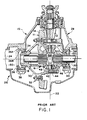
- a typical prior art differential head assembly 10 of a single reduction drive axle utilizing a gear set 11 comprising a pinion gear 12 meshingly engaged with a ring gear 14 is illustrated.
- a differential assembly 16 is fixed to the ring gear for driving two axle shafts 18 and 20.
- Axle shafts 18 and 20 drive the left and right hand, respectively, drive wheels (not shown) as is well known in the prior art.
- In the axis of rotation 22 of the pinion gear 12 is substantially perpendicular to the axis of rotation 24 of ring gear 14 (and the differential 16 and drive shafts 18 and 20).
- Heavy duty drive axles of this, and of the two speed planetary double reduction type are well known in the prior art.
- Drive axle assembly 10 also includes an axle housing 26 having a differential head portion 28.
- the ring gear 14 is mounted for rotation with a differential carrier 30 by means of bolt and nut assemblies 32.
- the differential carrier is rotationally supported in the housing portion 28 by means of tapered bearings 34 which are adjustably positioned by means of bearing adjustors 36 which are maintained in position by bearing adjustor lock members 38 and unshown bolts.
- the bearing adjustors 36 include outwardly extending lug members 36A which extend only partially radially inwardly from the outer periphery of the bearing adjusters to define an outboardly facing counterbore on the outboard faces of the bearing adjusters.
- the differential carrier 30 carries the differential spider member of 42 and which are rotatably received the differential pinion gears 44.
- the differential pinion gears are constantly meshed with the righthand and lefthand side gear (46 and 48), respectively, which side gears are rotatably engaged by the drive shafts 20 and 18 by means of a splined connection as is well known in the prior art.
- the splined connection between the inboard ends of the axle drive shafts and the hub portions of the side gears allows the axle shafts to be assembled to and disassembled from the drive axle gearing by passing same through the arm portions of the housing and centrally located openings or bores 36B in the bearing adjusters.
- the spaces designated generally as 50 within the axle housing 28 which are slightly outboard and adjacent the bearing adjusters 36 are relatively well protected and unused spaces which are particularly well suited for receipt of in-axle wheel speed sensors.
- the annular in-axle wheel speed sensor assembly 52 of the present invention which is adapted to be mounted to the outboard faces of one or, preferably, both of the bearing adjustors 36, and thus within space 50 within the axle housing, may be seen by reference to Figures 2, 3, 4, 8 and 10.
- the speed sensor assembly 52 is adapted to be received in and located by the counterbore on the outboard surface of the bearing adjusters defined by the lugs 36A thereof.
- Vehicular ABS and automated drive train systems are well known in the prior art and examples thereof may be seen by reference to above-mentioned U.S. Patents Nos. 3,920,284; 3,929,382; 4,168,866; 4,478,840; 4,818,035; 4,863,212; 4,361,060; 4,527,447; 4,643,048 and 4,860,861.
- Speed sensor assemblies for providing input signals to control units usually microprocessor based central processing units, are well known in the prior art as may be seen by reference to above-mentioned U.S. Patents Nos. RE 30522; 3,961,215; 4,862,025; 4,862,028 and 4,893,075.
- such speed sensor assemblies include a magnet, a coil, a tooth ferromagnetic rotor which is keyed to a monitored shaft for rotation therewith and a stator or sensor member rotationally fixed relative to a vehicle component.
- rotation of the rotor tooth and tooth spaces past the stator or sensor will result in the making and then breaking of a magnetic flux path which will result in pulses of increasing and decreasing induced current in the coil, the frequency and/or voltage of the induced current being indicative of the rotational speed of the rotor and those members rotating therewith.
- the rotor teeth may be replaced by undulations, apertures, etc.
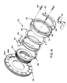
- the annular speed sensor assembly 52 of the present invention includes a ferromagnetic rotor member 54, a substantially annular permanent magnet 56, an annular coil member assembly 58, an annular ferromagnetic stator member 60 and an annular cover member 62 which is preferably of a relatively nonmagnetic flux conducting material such as stainless steel or brass or the like.
- a plurality of bolts or machine screws 64 are received through bolt holes 66 provided in the cover member 62 and are threadably engaged in internally threaded bores 68 provided in the adjuster members 36 to axially and rotationally mount the speed sensor assembly 52 to the outboard face of the adjuster member 36.
- the cover member 62 includes an axially extending wall 70 having an outer diameter surface 72 with an outer diameter just slightly less than inner diameter 74 of the counter bore defined on the outwardly facing surface of the bearing adjuster 36 by the lug members 36A whereby the assembly 52 is correctly radially positioned relative to the drive axle assembly.
- the bolts or machine screws 64 are of a nonferrous material and/or nonferrous spacers or sleeves are utilized therewith.
- the ferromagnetic rotor 54 includes an inboardly facing surface 76 for close abutment with the outboardly facing surface or face 36C of the bearing adjuster 36, and an axially extending outer diameter surface comprising an inboard portion 78, an outboard portion 80 and a radially outwardly extending array of teeth 82 interposed the inboard and outboard portions of the outer diameter surface.
- the radially outwardly extending teeth 82 define an outwardly facing abutment surface 84 which cooperates with the radially inwardly extending wall portion 86 of the cover member 62 to axially locate the rotor member 54.
- the outboard end of the rotor 54 extends axially outwardly from the other components of the speed sensor assembly 52 and defines a radially and axially inwardly tapered pilot surface 88 extending axially inwardly and radially downwardly to internal splines 90 which are intended for cooperation with external splines or projections (18A, see Fig. 10) to be provided on modified axle shafts whereby the rotor 54 will rotate with the axle shafts.
- the axially outwardly extending portion of the rotor 54 and the pilot or chamfer surface 88 both protects the speed sensor assembly 52 from the ends of axle shafts during assembly of the axle shafts to the differential side gears (see Fig. 9) and also pilots the ends of the axle shafts to ease such assembly.
- An annular coil member assembly 58 telescopically surrounds the inboard outer diameter surface 78 of the rotor.
- the coil assembly 58 includes a nonmagnetic bobbin member 58A which supports the coil windings 58B.
- the coil is wound of a copper, nickel, plated copper or other special alloy coil wire and the outer layer of the coil may be of a heavier gauge wire. For coils of this type, 1,600 to 2,500 turns per inch is typical.
- a pair of terminal connectors 92 and 94 are provided for the connection to the coil member windings for purposes of providing the sensor output signal.
- the terminal connector assemblies 92/94 are preferably housed in a single terminal block member 95 having two openings 95A and 95B for electrical connection to blade type connectors.
- the terminal block is located between a pair of tabs 58C provided on the bobbin 58A (see Figs. 11 and 11 A).
- the bobbin 58A also includes a plurality of extensions 58D which pass through openings provided in cover 62 for attaching the coil assembly 58 and stator 60 to the cover as a preassembled subassembly (see Fig. 8).
- An annular split ring type permanent magnet member 56 is telescopically received about the outer diameter of the annular coil member 58.
- the magnet member 56 is a plastic magnet for purposes of conserving weight and for providing added reliability.
- the magnetic member 56 includes an inboard surface 96 for abutting engagement with the outboard surface 36C of the ferromagnetic bearing adjuster 36 and an outboardly facing surface 98 for abutting engagement with the inboard surface of the stator member 60.
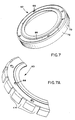
- a generally flat washer shaped stator member 60 is axially positioned between the inboard face of the radial wall 86 of the cover member 62 and the outboard face 98 of the permanent magnet 56.
- the stator includes a plurality of radially inwardly extending teeth 100 which are axially aligned with portions of the radially outwardly extending teeth 82 carried by the rotor 54 and are radially spaced therefrom by an air gap 102.
- the stator member 60 is provided with a plurality of generally concave shaped cut outs 104 allowing passage of the bolt means 64 therethrough and a circumferentially elongated cut out portion 106 allowing passage of the connector block 92/94 axially therethrough.
- the cut-outs 104 are generally radially extending and provide a relatively large clearance with screws 64 allowing the stator to move or float radially into a position of noncontact with the rotating rotor 54.
- the flux path 108 defined by the sensor assembly 52 of the present invention may be seen in greater detail by reference to Figure 8.
- the flux path is from magnet member 56 through ferromagnetic adjustor member 36 into the rotor member 54 from teeth 82 of the rotor to teeth 100 of the stator across the air gap 102, also called the working gap, when the teeth of the rotor and the stator are in circumferential alignment and from the stator back into the magnet member.
- the axial length 110 of surface 78, including teeth 82 is greater than the axial width 112 of the coil member 58 and magnet 56 to prevent jolts on surface 88 from being transmitted to the magnet or coil member during assembly of the axle shaft to the axle differential gearing.
- the cover member 62 is provided with a stamped plate 63 having a plurality of cut out portions 114 for cooperation with the locking member 38 whereby the differential adjusting member may be rotationally locked in its selected position.
- the cover member 62, stator member 60, coil member 58, and the connector assemblies 92/94 may be formed as a subassembly and electron beam welding of the stainless steel cover member and the coil bobbin to seal the sensor with hermetic seals at the connection points may be utilized.
- bi-filar coil windings may be utilized for redundancy as may vacuum impregnated coils and soft potting material rather than a rigid epoxy to minimize stress on the coil and termination points.
- a connector assembly 120 having a cap portion 122 designed to be sealingly and threadably received in a threaded bore 124 provided in the housing and defining a socket 126.
- a pair of wires 128 having blade connectors 130 for receipt into openings 95A and 95B of the terminal block extend from the cap member.
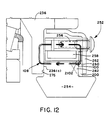
- Figure 12 is an enlarged view, similar to Figure 8, of an alternate embodiment 252 of the annular speed sensor assembly of the present invention.
- Components of assembly 252 similar in structure and function to those illustrated in Figure 8 and described above will be given the same reference numerals with a "2" prefix and will not be described in great detail.
- the assembly 252 includes a rotor 254, a stator 260, a magnet 256 and a coil 258, all performing the same functions as their counterparts in assembly 52 described above.
- the assembly cooperates with a ferromagnetic bearing adjuster 236 which defines a portion of the flux path 108.
- Surface 276 of rotor 254 abuts surface 236(c) of the adjuster.
- Assembly 252 differs from assembly 52 principally in that teeth 282 are axially extending and are axially, not radially, separated from the teeth 100 of stator 260 to define an axially, not radially, extending air gap or working gap 2102.
- a spacer or thrust washer which may be of self-lubricating material such as teflon or the like, 200 may be utilized to maintain a minimum axial separation between the rotor teeth 282 and stator teeth 100.
- the speed sensor is less susceptible to run out noise generation (both AM and FM), there is less noise resulting from tooth to tooth variation which allows the use of lower precision, less costly rotors and a higher output is possible due to the availability of large magnet volume and efficient magnetic circuit allowing the use of smaller diameter rotors, larger gaps, fewer turns of wire and/or less expensive magnets.
Landscapes
- Physics & Mathematics (AREA)
- General Physics & Mathematics (AREA)
- Transmission And Conversion Of Sensor Element Output (AREA)
- Indicating Or Recording The Presence, Absence, Or Direction Of Movement (AREA)
- Retarders (AREA)
Abstract
Description
- The present invention relates to an in-axle rotational speed sensor assembly for mounting to a fixed metallic (magnetic) member, such as a drive axle differential bearing adjustor, having a central opening therethrough for receipt of rotatable member, such as a shaft, the rotational speed of which is to measured.
- Automated vehicular systems such as brake control systems, antilock brake systems (ABS), traction control systems, differential lock-up systems and the like which utilize rotational speed sensors to provide a control input signal, usually indicative of wheel speed, to a controller, such as a microprocessor based electronic control unit (ECU), are well known in the prior art. Examples of such systems and/or sensors may be seen by reference to U.S. Patent Nos. RE 30,522; 3,961,215; 3,929,382, 3,556,610; 3,604,760; 4,585,280; 4,361,060; 3,768,840; 4,818,035 and 4,863,221, the disclosures of all of which are hereby incorporated by reference.
- Typically, such rotational speed sensor assemblies are electromagnetic in nature and rely on the alignment of rotor teeth, or spaces between rotor teeth, rotating past a sensor to complete or break, respectively, a magnetic flux path to produce a digital or analog signal indicative of the rotational speed of the rotor.
- Placement of wheel-speed sensor assemblies within the axle (i.e. "in-axle") to protect same is also known as may be seen by reference to U.S. Patent Nos. 3,769,533; 4,724,935; 4,836,616, 4,862,025 and 4,862,028, the disclosures of which are hereby incorporated by reference.
- The use of annular rotational speed sensor assemblies comprising an annular toothed stator/sensor which surrounds a rotating toothed rotor, or visa versa, is known in the prior art. Annular speed sensor assemblies are preferred over single or multiple point type sensor assemblies in certain situations as they provide a relatively high signal to noise ratio, tend to be self- compensating for run-out errors between the rotor and stator, and require little or no adjustment. Examples of wheel-end and/or in-axle annular speed sensor assemblies may be seen by reference to U.S. Patents Nos. 4,870,911; 4,027,753 and 4,689,557, the disclosures of which are incorporated herein by reference.
- The prior art in-axle wheel speed sensors, especially those designed for use with drive axles, were not totally satisfactory as they were point type not annular speed sensor assemblies and/or were not suitable for directly monitoring the speeds of both drive axle axle shafts and/or they were located at or adjacent the axle wheel ends, and not in the relatively more protected central portions adjacent the axle drive gearing.
- In accordance with the present invention, the drawbacks of the prior art have been minimized or overcome by the provision of an annular in-axle wheel speed sensor assembly for drive axles which is mounted in-axle at or adjacent to the relatively protected center of the drive axle assembly at either or both of the differential bearing adjustment members, which provides a pilot portion for axle shafts which are inserted through an opening in the bearing adjustor for driving engagement with the differential side gearing and which requires no adjustment. The above is accomplished by providing an annular in-axle wheel speed sensor for a drive axle which mounts to the drive axle differential bearing assembly adjustment member, which includes pilot means to assist assembly of the axle shafts to the drive axle differential side gearing and which requires no adjustment. Further, with relatively minor modifications, the sensor assembly may be modified for use with a wide variety of drive axles.
- This and other objects and advantages of the present invention will become apparent from a reading of the description of the preferred embodiment taken in connection with the attached drawings.
-
- Figure 1 is a partial sectional view of a typical prior art drive axle.
- Figure 2 is a perspective view of a portion of the annular wheel speed sensor assembly of the present invention.
- Figure 3 is a partially sectioned perspective view of the bearing adjuster of the present invention.
- Figure 4 is an exploded view of the annular wheel speed sensor assembly of the present invention.
- Figure 5 is a perspective view of the rotor member of the sensor assembly of Figure 2.
- Figure 6 is a perspective view of the stator member of the sensor assembly of Figure 2.
- Figure 7 is a perspective view of the cover member of the sensor assembly of Figure 2.
- Figure 8 is an enlarged partial view in section illustrating the magnetic flux path of the wheel speed sensor of Figure 2.
- Figure 9 is a partial schematic top view illustrating the type of assembly error that is protected against by the sensor assembly of the present invention.
- Figure 10 is a partial top view, in section, illustrating a drive axle with the in-axle annular speed sensors of the present invention assembled thereto.
- Figures 11 and 11A show exploded and assembled perspective views, respectively, of the coil bobbin and terminal block connector of the annular speed sensor assembly of the present invention.
- Figure 12 is an enlarged partial view, similar to Figure 8 of an alternate embodiment of the present invention.
- In the following description of the preferred embodiment, certain terms will be used for convenience in reference only and are not intended to be limiting. The terms "upwardly", "downwardly", "rightwardly" and "leftwardly" will designate directions in the drawings to which reference is made. The terms "inboard", and "outboard" will refer respectively to directions towards and away from, the geometric center of the vehicle drive axle as same is conventionally mounted in a vehicle. The terms "inwardly" and "outwardly" will refer to directions towards and away from, respectively, the geometric center of the device and designated parts thereof. The above applies to the words above specifically mentioned, derivatives thereof and words of similar import.
- Heavy duty drive axles utilizing ring gear/pinion gear right angle gear sets are well known in the prior art. Referring to Figure 1, a typical prior art
differential head assembly 10 of a single reduction drive axle utilizing a gear set 11 comprising apinion gear 12 meshingly engaged with aring gear 14 is illustrated. Adifferential assembly 16 is fixed to the ring gear for driving twoaxle shafts Axle shafts rotation 22 of thepinion gear 12 is substantially perpendicular to the axis ofrotation 24 of ring gear 14 (and the differential 16 anddrive shafts 18 and 20). Heavy duty drive axles of this, and of the two speed planetary double reduction type, are well known in the prior art. -
Drive axle assembly 10 also includes anaxle housing 26 having adifferential head portion 28. Thering gear 14 is mounted for rotation with adifferential carrier 30 by means of bolt andnut assemblies 32. The differential carrier is rotationally supported in thehousing portion 28 by means oftapered bearings 34 which are adjustably positioned by means ofbearing adjustors 36 which are maintained in position by bearingadjustor lock members 38 and unshown bolts. Thebearing adjustors 36 include outwardly extendinglug members 36A which extend only partially radially inwardly from the outer periphery of the bearing adjusters to define an outboardly facing counterbore on the outboard faces of the bearing adjusters. - The
differential carrier 30 carries the differential spider member of 42 and which are rotatably received thedifferential pinion gears 44. The differential pinion gears are constantly meshed with the righthand and lefthand side gear (46 and 48), respectively, which side gears are rotatably engaged by thedrive shafts bores 36B in the bearing adjusters. - As may be appreciated by reference to Figure 1, the spaces designated generally as 50 within the
axle housing 28 which are slightly outboard and adjacent thebearing adjusters 36 are relatively well protected and unused spaces which are particularly well suited for receipt of in-axle wheel speed sensors. - The annular in-axle wheel
speed sensor assembly 52 of the present invention, which is adapted to be mounted to the outboard faces of one or, preferably, both of thebearing adjustors 36, and thus withinspace 50 within the axle housing, may be seen by reference to Figures 2, 3, 4, 8 and 10. Thespeed sensor assembly 52 is adapted to be received in and located by the counterbore on the outboard surface of the bearing adjusters defined by thelugs 36A thereof. - Vehicular ABS and automated drive train systems are well known in the prior art and examples thereof may be seen by reference to above-mentioned U.S. Patents Nos. 3,920,284; 3,929,382; 4,168,866; 4,478,840; 4,818,035; 4,863,212; 4,361,060; 4,527,447; 4,643,048 and 4,860,861. Speed sensor assemblies for providing input signals to control units, usually microprocessor based central processing units, are well known in the prior art as may be seen by reference to above-mentioned U.S. Patents Nos. RE 30522; 3,961,215; 4,862,025; 4,862,028 and 4,893,075.
- Typically, such speed sensor assemblies include a magnet, a coil, a tooth ferromagnetic rotor which is keyed to a monitored shaft for rotation therewith and a stator or sensor member rotationally fixed relative to a vehicle component. Usually, rotation of the rotor tooth and tooth spaces past the stator or sensor will result in the making and then breaking of a magnetic flux path which will result in pulses of increasing and decreasing induced current in the coil, the frequency and/or voltage of the induced current being indicative of the rotational speed of the rotor and those members rotating therewith. Of course, the rotor teeth may be replaced by undulations, apertures, etc.
- The annular
speed sensor assembly 52 of the present invention includes aferromagnetic rotor member 54, a substantially annularpermanent magnet 56, an annularcoil member assembly 58, an annularferromagnetic stator member 60 and anannular cover member 62 which is preferably of a relatively nonmagnetic flux conducting material such as stainless steel or brass or the like. A plurality of bolts ormachine screws 64 are received throughbolt holes 66 provided in thecover member 62 and are threadably engaged in internally threaded bores 68 provided in theadjuster members 36 to axially and rotationally mount thespeed sensor assembly 52 to the outboard face of theadjuster member 36. Thecover member 62 includes an axially extendingwall 70 having anouter diameter surface 72 with an outer diameter just slightly less thaninner diameter 74 of the counter bore defined on the outwardly facing surface of thebearing adjuster 36 by thelug members 36A whereby theassembly 52 is correctly radially positioned relative to the drive axle assembly. - Preferably the bolts or
machine screws 64 are of a nonferrous material and/or nonferrous spacers or sleeves are utilized therewith. - The
ferromagnetic rotor 54 includes an inboardly facingsurface 76 for close abutment with the outboardly facing surface orface 36C of thebearing adjuster 36, and an axially extending outer diameter surface comprising aninboard portion 78, anoutboard portion 80 and a radially outwardly extending array ofteeth 82 interposed the inboard and outboard portions of the outer diameter surface. The radially outwardly extendingteeth 82, define an outwardly facingabutment surface 84 which cooperates with the radially inwardly extendingwall portion 86 of thecover member 62 to axially locate therotor member 54. The outboard end of therotor 54 extends axially outwardly from the other components of thespeed sensor assembly 52 and defines a radially and axially inwardlytapered pilot surface 88 extending axially inwardly and radially downwardly tointernal splines 90 which are intended for cooperation with external splines or projections (18A, see Fig. 10) to be provided on modified axle shafts whereby therotor 54 will rotate with the axle shafts. The axially outwardly extending portion of therotor 54 and the pilot orchamfer surface 88 both protects thespeed sensor assembly 52 from the ends of axle shafts during assembly of the axle shafts to the differential side gears (see Fig. 9) and also pilots the ends of the axle shafts to ease such assembly. - An annular
coil member assembly 58 telescopically surrounds the inboardouter diameter surface 78 of the rotor. Thecoil assembly 58 includes anonmagnetic bobbin member 58A which supports the coil windings 58B. To provide increased reliability of the sensor, preferably the coil is wound of a copper, nickel, plated copper or other special alloy coil wire and the outer layer of the coil may be of a heavier gauge wire. For coils of this type, 1,600 to 2,500 turns per inch is typical. - A pair of terminal connectors 92 and 94 are provided for the connection to the coil member windings for purposes of providing the sensor output signal. The terminal connector assemblies 92/94 are preferably housed in a single
terminal block member 95 having twoopenings 95A and 95B for electrical connection to blade type connectors. The terminal block is located between a pair oftabs 58C provided on thebobbin 58A (see Figs. 11 and 11 A). - The
bobbin 58A also includes a plurality of extensions 58D which pass through openings provided incover 62 for attaching thecoil assembly 58 andstator 60 to the cover as a preassembled subassembly (see Fig. 8). - An annular split ring type
permanent magnet member 56 is telescopically received about the outer diameter of theannular coil member 58. Preferably, themagnet member 56 is a plastic magnet for purposes of conserving weight and for providing added reliability. Themagnetic member 56 includes aninboard surface 96 for abutting engagement with theoutboard surface 36C of theferromagnetic bearing adjuster 36 and anoutboardly facing surface 98 for abutting engagement with the inboard surface of thestator member 60. - A generally flat washer shaped
stator member 60 is axially positioned between the inboard face of theradial wall 86 of thecover member 62 and theoutboard face 98 of thepermanent magnet 56. The stator includes a plurality of radially inwardly extendingteeth 100 which are axially aligned with portions of the radially outwardly extendingteeth 82 carried by therotor 54 and are radially spaced therefrom by anair gap 102. At its outer diameter, thestator member 60 is provided with a plurality of generally concave shapedcut outs 104 allowing passage of the bolt means 64 therethrough and a circumferentially elongated cut outportion 106 allowing passage of the connector block 92/94 axially therethrough. Preferably, the cut-outs 104 are generally radially extending and provide a relatively large clearance withscrews 64 allowing the stator to move or float radially into a position of noncontact with the rotatingrotor 54. - The
flux path 108 defined by thesensor assembly 52 of the present invention may be seen in greater detail by reference to Figure 8. In the counterclockwise direction, the flux path is frommagnet member 56 throughferromagnetic adjustor member 36 into therotor member 54 fromteeth 82 of the rotor toteeth 100 of the stator across theair gap 102, also called the working gap, when the teeth of the rotor and the stator are in circumferential alignment and from the stator back into the magnet member. It is important to note, that by positioning the axially aligned portions of theteeth ferromagnetic adjuster member 36 and at a position surrounded by the relatively lowpermeability cover member 62, short circuiting of the magnetic flux path across from the rotor to the stator other than across theair gap 102 when the teeth are in circumferential alignment is minimized. - To provide protection to the
coil member 58,magnet member 56 andstator 60, theaxial length 110 ofsurface 78, includingteeth 82 is greater than theaxial width 112 of thecoil member 58 andmagnet 56 to prevent jolts onsurface 88 from being transmitted to the magnet or coil member during assembly of the axle shaft to the axle differential gearing. - The
cover member 62 is provided with a stampedplate 63 having a plurality of cut out portions 114 for cooperation with the lockingmember 38 whereby the differential adjusting member may be rotationally locked in its selected position. - The
cover member 62,stator member 60,coil member 58, and the connector assemblies 92/94 may be formed as a subassembly and electron beam welding of the stainless steel cover member and the coil bobbin to seal the sensor with hermetic seals at the connection points may be utilized. To increase the reliability and to minimize the requirement of servicing, bi-filar coil windings may be utilized for redundancy as may vacuum impregnated coils and soft potting material rather than a rigid epoxy to minimize stress on the coil and termination points. - Referring to Figure 10 and 10A, a
connector assembly 120 is provided having acap portion 122 designed to be sealingly and threadably received in a threadedbore 124 provided in the housing and defining asocket 126. A pair ofwires 128 havingblade connectors 130 for receipt intoopenings 95A and 95B of the terminal block extend from the cap member. - Figure 12 is an enlarged view, similar to Figure 8, of an
alternate embodiment 252 of the annular speed sensor assembly of the present invention. Components ofassembly 252 similar in structure and function to those illustrated in Figure 8 and described above will be given the same reference numerals with a "2" prefix and will not be described in great detail. - The
assembly 252 includes arotor 254, astator 260, amagnet 256 and acoil 258, all performing the same functions as their counterparts inassembly 52 described above. The assembly cooperates with aferromagnetic bearing adjuster 236 which defines a portion of theflux path 108.Surface 276 ofrotor 254 abuts surface 236(c) of the adjuster. -
Assembly 252 differs fromassembly 52 principally in thatteeth 282 are axially extending and are axially, not radially, separated from theteeth 100 ofstator 260 to define an axially, not radially, extending air gap or workinggap 2102. - It has been found that a sensor assembly with an axially extending air gap is more tolerant of radial run out between the relatively rotating component.
- A spacer or thrust washer, which may be of self-lubricating material such as teflon or the like, 200 may be utilized to maintain a minimum axial separation between the
rotor teeth 282 andstator teeth 100. - Further advantages of the annular speed sensor are that the speed sensor is less susceptible to run out noise generation (both AM and FM), there is less noise resulting from tooth to tooth variation which allows the use of lower precision, less costly rotors and a higher output is possible due to the availability of large magnet volume and efficient magnetic circuit allowing the use of smaller diameter rotors, larger gaps, fewer turns of wire and/or less expensive magnets.
- It is also noted, that by utilization of the existing
ferromagnetic bearing adjustor 36 as a portion of the annular speed sensormagnetic flux path 108 an additional ferromagnetic member need not be supplied with resulting savings in weight and cost. - Although the preferred embodiment of the present invention has been described with a certain degree of particularity, it is understood, of course, that certain substitutions for rearrangement of the parts may be resorted to without departing from the spirit and the scope of the present invention as hereinafter claimed.
Claims (20)
Applications Claiming Priority (4)
| Application Number | Priority Date | Filing Date | Title |
|---|---|---|---|
| US57838390A | 1990-09-07 | 1990-09-07 | |
| US578383 | 1990-09-07 | ||
| US622108 | 1990-12-03 | ||
| US07/622,108 US5227719A (en) | 1990-09-07 | 1990-12-03 | Drive axle in-axle annular speed sensor |
Publications (2)
| Publication Number | Publication Date |
|---|---|
| EP0474064A1 true EP0474064A1 (en) | 1992-03-11 |
| EP0474064B1 EP0474064B1 (en) | 1995-04-05 |
Family
ID=27077486
Family Applications (1)
| Application Number | Title | Priority Date | Filing Date |
|---|---|---|---|
| EP91114159A Expired - Lifetime EP0474064B1 (en) | 1990-09-07 | 1991-08-23 | Annular speed sensor |
Country Status (17)
| Country | Link |
|---|---|
| US (1) | US5227719A (en) |
| EP (1) | EP0474064B1 (en) |
| JP (1) | JP3205840B2 (en) |
| KR (1) | KR960005343B1 (en) |
| CN (1) | CN1029260C (en) |
| AR (1) | AR247949A1 (en) |
| AT (1) | ATE120861T1 (en) |
| AU (1) | AU657883B2 (en) |
| BR (1) | BR9103871A (en) |
| CA (1) | CA2049893C (en) |
| DE (1) | DE69108647T2 (en) |
| ES (1) | ES2070383T3 (en) |
| FI (1) | FI101752B1 (en) |
| HU (1) | HU212558B (en) |
| MX (1) | MX174267B (en) |
| TR (1) | TR25786A (en) |
| TW (1) | TW197987B (en) |
Cited By (3)
| Publication number | Priority date | Publication date | Assignee | Title |
|---|---|---|---|---|
| EP0599179A1 (en) * | 1992-11-23 | 1994-06-01 | Eaton Corporation | Annular speed sensor with strain relief |
| EP0721106A3 (en) * | 1994-12-27 | 1996-07-31 | Ssi Technologies Inc | |
| US6493622B1 (en) * | 1999-10-16 | 2002-12-10 | Robert Bosch Gmbh | Method and device for protecting the differentials of a motor vehicle |
Families Citing this family (24)
| Publication number | Priority date | Publication date | Assignee | Title |
|---|---|---|---|---|
| US5491407A (en) * | 1995-02-03 | 1996-02-13 | Kearney-National, Inc. | Wheel bearing speed sensor |
| US5965806A (en) * | 1997-09-30 | 1999-10-12 | Cummins Engine Company, Inc. | Engine crankshaft sensing system |
| US6131547A (en) * | 1998-02-27 | 2000-10-17 | Cummins Engine Company, Inc. | Electronic engine speed and position apparatus for camshaft gear applications |
| US7157901B1 (en) | 2000-02-08 | 2007-01-02 | Robert Bosch Gmbh | Inductive sensor (speed sensor) with a conical coil base body |
| US7656153B2 (en) * | 2005-01-24 | 2010-02-02 | Allan Westersten | Metal detector with improved receiver coil |
| KR100624331B1 (en) * | 2005-03-11 | 2006-09-19 | 한국하니웰 주식회사 | Sensor for detecting rotational speed |
| KR20060100896A (en) * | 2005-03-18 | 2006-09-21 | 한국하니웰 주식회사 | Sensor for detecting rotational speed |
| DE102008001999A1 (en) * | 2007-11-14 | 2009-05-20 | Robert Bosch Gmbh | Offset compensation circuit and thus equipped rotation rate sensor |
| JP5373447B2 (en) * | 2009-03-30 | 2013-12-18 | 株式会社小松製作所 | Wheel rotation speed detection device |
| US8167762B2 (en) * | 2009-04-24 | 2012-05-01 | American Axle & Manufacturing, Inc. | Drive axle assembly with wheel speed measurement system |
| US9207102B2 (en) | 2012-06-21 | 2015-12-08 | Dana Automotive Systems Group, Llc | Anti-lock brake rotor tone ring cartridge and shaft guide |
| DE102013201328B4 (en) * | 2013-01-28 | 2015-06-11 | Deckel Maho Pfronten Gmbh | Machining unit for a program-controlled machine tool |
| CN103149381A (en) * | 2013-03-01 | 2013-06-12 | 哈尔滨电机厂有限责任公司 | Rotor wind speed and wind quantity measuring system of water pumping energy storage machine set |
| CN105987657B (en) * | 2015-02-12 | 2018-12-07 | 珠海格力电器股份有限公司 | Eddy current sensor for rotating shaft and rotating shaft device |
| CN106153972B (en) * | 2015-03-26 | 2020-06-09 | 广东德昌电机有限公司 | Waveform conversion circuit, rotating speed detection device and motor system |
| USD851684S1 (en) * | 2016-03-15 | 2019-06-18 | Eaton Corporation | Plenum transport retainer clip with locking finger |
| USD791839S1 (en) * | 2016-03-15 | 2017-07-11 | Eaton Corporation | Plenum retaining clip |
| CN107765025B (en) * | 2016-08-15 | 2019-12-17 | 德纳重型车辆系统集团有限责任公司 | Internal two-channel wheel speed sensor system |
| KR101990092B1 (en) * | 2017-03-24 | 2019-06-17 | 주식회사 엔씨소프트 | Apparatus and method for compressing image |
| USD826485S1 (en) * | 2017-09-29 | 2018-08-21 | Miller Manufacturing Company | Livestock water trough heater |
| CN107860937A (en) * | 2017-10-11 | 2018-03-30 | 中国航发西安动力控制科技有限公司 | A kind of centrifugal revolution speed sensing device assembly |
| CN108761116B (en) * | 2018-07-27 | 2024-04-19 | 西安航空制动科技有限公司 | Speed sensor for hollow wheel |
| IT201800010494A1 (en) * | 2018-11-22 | 2020-05-22 | Skf Ab | WHEEL HUB GROUP WITH A MAGNETIC SIGNAL AMPLIFICATION DEVICE |
| US11485176B2 (en) | 2019-09-25 | 2022-11-01 | Deere & Company | Wheel speed sensing system |
Citations (4)
| Publication number | Priority date | Publication date | Assignee | Title |
|---|---|---|---|---|
| FR1576303A (en) * | 1967-08-17 | 1969-07-25 | ||
| DE1911487A1 (en) * | 1968-07-25 | 1970-02-19 | Kelsey Hayes Co | Speed transducer |
| US4901562A (en) * | 1989-03-31 | 1990-02-20 | Dana Corporation | Vehicle wheel speed sensor for a drive axle |
| EP0357870A2 (en) * | 1988-08-24 | 1990-03-14 | Rockwell International Corporation | Unitary rotational speed sensor |
Family Cites Families (4)
| Publication number | Priority date | Publication date | Assignee | Title |
|---|---|---|---|---|
| US2462761A (en) * | 1946-02-12 | 1949-02-22 | Singer Mfg Co | Inductor alternator |
| US3739211A (en) * | 1971-10-15 | 1973-06-12 | Amper Corp | Magnetic tachometer |
| US4027753A (en) * | 1976-04-15 | 1977-06-07 | The B.F. Goodrich Company | In-axle vehicle wheel speed sensing device |
| JPS5328767U (en) * | 1976-08-19 | 1978-03-11 |
-
1990
- 1990-12-03 US US07/622,108 patent/US5227719A/en not_active Expired - Lifetime
-
1991
- 1991-08-23 ES ES91114159T patent/ES2070383T3/en not_active Expired - Lifetime
- 1991-08-23 AT AT91114159T patent/ATE120861T1/en not_active IP Right Cessation
- 1991-08-23 DE DE69108647T patent/DE69108647T2/en not_active Expired - Fee Related
- 1991-08-23 EP EP91114159A patent/EP0474064B1/en not_active Expired - Lifetime
- 1991-08-26 CA CA002049893A patent/CA2049893C/en not_active Expired - Fee Related
- 1991-08-26 AR AR91320484A patent/AR247949A1/en active
- 1991-08-27 AU AU82764/91A patent/AU657883B2/en not_active Ceased
- 1991-08-28 TW TW080106805A patent/TW197987B/zh active
- 1991-09-02 TR TR91/0853A patent/TR25786A/en unknown
- 1991-09-04 BR BR919103871A patent/BR9103871A/en not_active IP Right Cessation
- 1991-09-05 JP JP25469091A patent/JP3205840B2/en not_active Expired - Fee Related
- 1991-09-06 HU HU912894A patent/HU212558B/en not_active IP Right Cessation
- 1991-09-06 KR KR1019910015551A patent/KR960005343B1/en not_active IP Right Cessation
- 1991-09-06 FI FI914223A patent/FI101752B1/en active
- 1991-09-06 MX MX9100987A patent/MX174267B/en not_active IP Right Cessation
- 1991-09-07 CN CN91109285A patent/CN1029260C/en not_active Expired - Fee Related
Patent Citations (4)
| Publication number | Priority date | Publication date | Assignee | Title |
|---|---|---|---|---|
| FR1576303A (en) * | 1967-08-17 | 1969-07-25 | ||
| DE1911487A1 (en) * | 1968-07-25 | 1970-02-19 | Kelsey Hayes Co | Speed transducer |
| EP0357870A2 (en) * | 1988-08-24 | 1990-03-14 | Rockwell International Corporation | Unitary rotational speed sensor |
| US4901562A (en) * | 1989-03-31 | 1990-02-20 | Dana Corporation | Vehicle wheel speed sensor for a drive axle |
Cited By (4)
| Publication number | Priority date | Publication date | Assignee | Title |
|---|---|---|---|---|
| EP0599179A1 (en) * | 1992-11-23 | 1994-06-01 | Eaton Corporation | Annular speed sensor with strain relief |
| AU660903B2 (en) * | 1992-11-23 | 1995-07-06 | Eaton Corporation | Annular speed sensor with strain relief |
| EP0721106A3 (en) * | 1994-12-27 | 1996-07-31 | Ssi Technologies Inc | |
| US6493622B1 (en) * | 1999-10-16 | 2002-12-10 | Robert Bosch Gmbh | Method and device for protecting the differentials of a motor vehicle |
Also Published As
| Publication number | Publication date |
|---|---|
| ES2070383T3 (en) | 1995-06-01 |
| KR960005343B1 (en) | 1996-04-24 |
| EP0474064B1 (en) | 1995-04-05 |
| TR25786A (en) | 1993-09-01 |
| FI914223A (en) | 1992-03-08 |
| HU212558B (en) | 1996-08-29 |
| HU912894D0 (en) | 1992-01-28 |
| US5227719A (en) | 1993-07-13 |
| DE69108647D1 (en) | 1995-05-11 |
| ATE120861T1 (en) | 1995-04-15 |
| BR9103871A (en) | 1992-05-26 |
| HUT59232A (en) | 1992-04-28 |
| DE69108647T2 (en) | 1995-08-10 |
| FI101752B (en) | 1998-08-14 |
| FI101752B1 (en) | 1998-08-14 |
| AU8276491A (en) | 1992-03-12 |
| CN1029260C (en) | 1995-07-05 |
| JP3205840B2 (en) | 2001-09-04 |
| CN1060534A (en) | 1992-04-22 |
| JPH05149960A (en) | 1993-06-15 |
| AR247949A1 (en) | 1995-04-28 |
| TW197987B (en) | 1993-01-11 |
| FI914223A0 (en) | 1991-09-06 |
| CA2049893A1 (en) | 1992-03-08 |
| CA2049893C (en) | 1997-12-30 |
| AU657883B2 (en) | 1995-03-23 |
| MX174267B (en) | 1994-05-02 |
Similar Documents
| Publication | Publication Date | Title |
|---|---|---|
| US5227719A (en) | Drive axle in-axle annular speed sensor | |
| US4937522A (en) | Speed sensor pickup assembly with slotted magnet | |
| US5291130A (en) | Vehicle wheel speed sensor employing an adaptable rotor cap | |
| EP2243673B1 (en) | Drive axle assembly with wheel speed measurement system | |
| EP0362527B1 (en) | Speed sensor pickup assembly with anti-cross talk means | |
| US3916234A (en) | Vehicle wheel speed sensor | |
| US5223760A (en) | Wheel speed sensor for drive axle | |
| CA1333964C (en) | Unitary rotational speed sensor | |
| EP0693689B1 (en) | Hub unit with rotation speed sensor | |
| EP0542064A1 (en) | Vehicle wheel speed sensor | |
| CA1106469A (en) | Antilock sensor assembly | |
| GB2321788A (en) | Axle-mounted inductor generator | |
| US4862025A (en) | Dual speed sensor pickup assembly | |
| EP0599179B1 (en) | Annular speed sensor with strain relief | |
| US5537032A (en) | Shape coupled wheel speed sensor | |
| EP0442121B1 (en) | Gearing system comprising a rotational speed sensor | |
| US4221985A (en) | Vehicle tachometer generator | |
| JPS6123806Y2 (en) | ||
| CN211701755U (en) | Wheel hub subassembly and electric automobile | |
| JPH0815289A (en) | Wheel speed detecting apparatus |
Legal Events
| Date | Code | Title | Description |
|---|---|---|---|
| PUAI | Public reference made under article 153(3) epc to a published international application that has entered the european phase |
Free format text: ORIGINAL CODE: 0009012 |
|
| AK | Designated contracting states |
Kind code of ref document: A1 Designated state(s): AT BE CH DE ES FR GB IT LI NL SE |
|
| 17P | Request for examination filed |
Effective date: 19920407 |
|
| 17Q | First examination report despatched |
Effective date: 19931026 |
|
| GRAA | (expected) grant |
Free format text: ORIGINAL CODE: 0009210 |
|
| AK | Designated contracting states |
Kind code of ref document: B1 Designated state(s): AT BE CH DE ES FR GB IT LI NL SE |
|
| REF | Corresponds to: |
Ref document number: 120861 Country of ref document: AT Date of ref document: 19950415 Kind code of ref document: T |
|
| REF | Corresponds to: |
Ref document number: 69108647 Country of ref document: DE Date of ref document: 19950511 |
|
| ITF | It: translation for a ep patent filed | ||
| REG | Reference to a national code |
Ref country code: ES Ref legal event code: FG2A Ref document number: 2070383 Country of ref document: ES Kind code of ref document: T3 |
|
| ET | Fr: translation filed | ||
| PLBE | No opposition filed within time limit |
Free format text: ORIGINAL CODE: 0009261 |
|
| STAA | Information on the status of an ep patent application or granted ep patent |
Free format text: STATUS: NO OPPOSITION FILED WITHIN TIME LIMIT |
|
| 26N | No opposition filed | ||
| PGFP | Annual fee paid to national office [announced via postgrant information from national office to epo] |
Ref country code: NL Payment date: 19990630 Year of fee payment: 9 |
|
| PGFP | Annual fee paid to national office [announced via postgrant information from national office to epo] |
Ref country code: GB Payment date: 19990702 Year of fee payment: 9 Ref country code: AT Payment date: 19990702 Year of fee payment: 9 |
|
| PGFP | Annual fee paid to national office [announced via postgrant information from national office to epo] |
Ref country code: SE Payment date: 19990802 Year of fee payment: 9 Ref country code: FR Payment date: 19990802 Year of fee payment: 9 |
|
| PGFP | Annual fee paid to national office [announced via postgrant information from national office to epo] |
Ref country code: ES Payment date: 19990811 Year of fee payment: 9 |
|
| PGFP | Annual fee paid to national office [announced via postgrant information from national office to epo] |
Ref country code: DE Payment date: 19990831 Year of fee payment: 9 |
|
| PGFP | Annual fee paid to national office [announced via postgrant information from national office to epo] |
Ref country code: BE Payment date: 19990914 Year of fee payment: 9 |
|
| PGFP | Annual fee paid to national office [announced via postgrant information from national office to epo] |
Ref country code: CH Payment date: 19991021 Year of fee payment: 9 |
|
| PG25 | Lapsed in a contracting state [announced via postgrant information from national office to epo] |
Ref country code: GB Free format text: LAPSE BECAUSE OF NON-PAYMENT OF DUE FEES Effective date: 20000823 Ref country code: AT Free format text: LAPSE BECAUSE OF NON-PAYMENT OF DUE FEES Effective date: 20000823 |
|
| PG25 | Lapsed in a contracting state [announced via postgrant information from national office to epo] |
Ref country code: SE Free format text: LAPSE BECAUSE OF NON-PAYMENT OF DUE FEES Effective date: 20000824 Ref country code: ES Free format text: LAPSE BECAUSE OF NON-PAYMENT OF DUE FEES Effective date: 20000824 |
|
| PG25 | Lapsed in a contracting state [announced via postgrant information from national office to epo] |
Ref country code: LI Free format text: LAPSE BECAUSE OF NON-PAYMENT OF DUE FEES Effective date: 20000831 Ref country code: CH Free format text: LAPSE BECAUSE OF NON-PAYMENT OF DUE FEES Effective date: 20000831 Ref country code: BE Free format text: LAPSE BECAUSE OF NON-PAYMENT OF DUE FEES Effective date: 20000831 |
|
| BERE | Be: lapsed |
Owner name: EATON CORP. Effective date: 20000831 |
|
| PG25 | Lapsed in a contracting state [announced via postgrant information from national office to epo] |
Ref country code: NL Free format text: LAPSE BECAUSE OF NON-PAYMENT OF DUE FEES Effective date: 20010301 |
|
| REG | Reference to a national code |
Ref country code: CH Ref legal event code: PL |
|
| GBPC | Gb: european patent ceased through non-payment of renewal fee |
Effective date: 20000823 |
|
| EUG | Se: european patent has lapsed |
Ref document number: 91114159.6 |
|
| PG25 | Lapsed in a contracting state [announced via postgrant information from national office to epo] |
Ref country code: FR Free format text: LAPSE BECAUSE OF NON-PAYMENT OF DUE FEES Effective date: 20010430 |
|
| NLV4 | Nl: lapsed or anulled due to non-payment of the annual fee |
Effective date: 20010301 |
|
| PG25 | Lapsed in a contracting state [announced via postgrant information from national office to epo] |
Ref country code: DE Free format text: LAPSE BECAUSE OF NON-PAYMENT OF DUE FEES Effective date: 20010501 |
|
| REG | Reference to a national code |
Ref country code: FR Ref legal event code: ST |
|
| REG | Reference to a national code |
Ref country code: ES Ref legal event code: FD2A Effective date: 20010911 |
|
| PG25 | Lapsed in a contracting state [announced via postgrant information from national office to epo] |
Ref country code: IT Free format text: LAPSE BECAUSE OF NON-PAYMENT OF DUE FEES Effective date: 20050823 |