EP0473820A1 - Affichage sans joint d'images vidéomultiples - Google Patents
Affichage sans joint d'images vidéomultiples Download PDFInfo
- Publication number
- EP0473820A1 EP0473820A1 EP90117065A EP90117065A EP0473820A1 EP 0473820 A1 EP0473820 A1 EP 0473820A1 EP 90117065 A EP90117065 A EP 90117065A EP 90117065 A EP90117065 A EP 90117065A EP 0473820 A1 EP0473820 A1 EP 0473820A1
- Authority
- EP
- European Patent Office
- Prior art keywords
- image
- discrete
- images
- video
- video signal
- Prior art date
- Legal status (The legal status is an assumption and is not a legal conclusion. Google has not performed a legal analysis and makes no representation as to the accuracy of the status listed.)
- Withdrawn
Links
Images


Classifications
-
- H—ELECTRICITY
- H04—ELECTRIC COMMUNICATION TECHNIQUE
- H04N—PICTORIAL COMMUNICATION, e.g. TELEVISION
- H04N9/00—Details of colour television systems
- H04N9/12—Picture reproducers
- H04N9/31—Projection devices for colour picture display, e.g. using electronic spatial light modulators [ESLM]
-
- H—ELECTRICITY
- H04—ELECTRIC COMMUNICATION TECHNIQUE
- H04N—PICTORIAL COMMUNICATION, e.g. TELEVISION
- H04N9/00—Details of colour television systems
- H04N9/12—Picture reproducers
- H04N9/31—Projection devices for colour picture display, e.g. using electronic spatial light modulators [ESLM]
- H04N9/3141—Constructional details thereof
- H04N9/3147—Multi-projection systems
Definitions
- the present invention pertains to the field of video image displays and more particularly to a method and apparatus for projecting a seamless video display from multiple video signals.
- the broadcast standards define both the aspect ratio and the resolution of the image.
- the broadcast standards limit resolution by defining the number of horizontal lines per frame and the number of picture elements in each line.
- An increase in the size or horizontal scope of a commercial television image necessarily brings no increase in the number of lines or the number of picture elements in that image. Therefore, a very large picture will not be as sharp and clear as a smaller image.
- Several commercial-type video signals may be combined to form a single image with a different aspect ratio, with more picture elements, or with more lines per frame. However, this requires either combining several projectors to form that single image, or developing a whole new format different from the commercial standards.
- the present invention includes a method and apparatus for producing a seamless video display from multiple images.
- the invention comprises a method for producing a seamless image from at least two discrete images where each image overlaps with at least one other image by ramping the projected brightness of the overlapping portions of each image.
- the invention also comprises an apparatus including at least two video signal generators where each generator produces a video signal that corresponds to a discrete image and each image overlaps at least one other image.
- the video signals are sent to at least two ramp generators.
- At least one ramp generator is coupled to each video signal generator.
- the ramp generators ramp the parts of the video signals that correspond to the overlaps between the images.
- At least one projector is coupled to each ramp generator.
- the images produced by the projectors, corresponding to the ramped video signals, are projected onto a screen.
- a synchronizer is coupled to the video signal generators for synchronizing the images.
- the present invention produces a seamless apparent image by overlapping the separate images and then ramping the brightness of the images at the seams between the separate images.
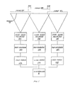
- three video signal generators 10A, 10B, 10C operate in parallel. They generate video signals which correspond to discrete images as explained below.
- the signal generators are video disc players. Pioneer Model LDZ 6000A is suitable. Each video disc player transmits a unique frame number for each discrete image to a synchronizer 8.
- the synchronizer compares the frame numbers received from the video disc players and then regulates the video disc players so they produce like numbered images at the same time. In this way, the synchronizer maintains synchronous parallel operation for the whole system.
- An APh Model VDU-1 is a suitable synchronizer.
- the video signal generators each transmit their video signals, in parallel, to the corresponding one of three ramp generators 12A, 12B, 12C.
- the ramp generators ramp the signal, as will be described in more detail below.
- Commercially available special effects generators such as the Vidicraft Model SEG-200, may be used for ramp generators.
- Each of the ramp generators sends the ramped signal to the corresponding one of three video image projectors 14A, 14B, 14C.
- Commercially available projectors such as the Panasonic Model PT-1 01 N, are suitable.
- the projectors convert the electrical signals to light beams. The three beams are projected onto a single screen 16, in parallel.
- the screen displays three discrete images 18A, 18B, 18C which correspond to the three ramped video signals. Where the images come together there are overlaps 20A, 20B.
- the left overlap 20A occurs where the left image 18A and the center image 18B are both projected onto the same part of the screen.
- the right overlap 20B occurs where the center image 18B and the right image 18C are both projected onto the same part of the screen.
- the information in the video signals corresponding to the overlaps 20A, 20B is duplicated in the video signals for the three images 18A, 18B, 18C. That is, for the left overlap 20A, the right portion of the left image 18A that is projected onto the left overlap 20A, must be virtually identical to the left portion of the center image 18B that is projected onto the left overlap 20A. Otherwise, neither of the overlapping portions of the two images 18A, 18B will appear clearly on the screen. The same thing applies for the right overlap 20B.
- the three images displayed on the screen appear to be one continuous, seamless image almost three times as wide as a single video image but with the same clarity and sharpness as a single video image.
- This composite larger image which appears on the screen will be referred to as the apparent image.
- the nature of the video signal emitted by the video signal generators is illustrated in FIG. 2.
- the video signal 28 has a sequence of horizontal synchronization signals 30A, 30B each followed by amplitude signals 32A, 32B.
- the video signal includes other components as well, but they are not important to this discussion and are not shown in FIG. 2.
- Each synchronization and amplitude signal pair e.g. 30A and 32A, corresponds to a single scan line traced across the screen.
- the synchronization signal indicates the start of each scan line.
- the amplitude signal indicates the brightness of the projector beam as the line is traced.
- the projector begins to trace a scan line when it receives a synchronization signal.
- a beam of electrons from an electron gun is aimed at the top left corner of a phosphorous screen.
- the electron beam is then deflected to the right across the top of the screen.
- the number of electrons emitted by the gun is regulated by the amplitude signal.
- the electron beam moves back to the left of the screen and traces a second scan line immediately below the first. This is repeated with each synchronization signal and each amplitude signal, until the electron beam reaches the bottom right hand corner of the screen.
- the beam has then drawn one complete image and, upon receiving a vertical synchronization signal, returns to the top left of the screen to draw the next image.
- the lines are drawn so quickly that there appears to be a single moving image rather than a series of line tracings.
- the number of lines and picture elements per image as well as a host of other details are determined by the standards for the particular format and are intrinsic to the video signal.
- FIG. 3 demonstrates how video signals are ramped according to the present invention.
- the three parallel systems each consisting of a video signal generator, a ramp generator and a video image projector are synchronized. For each image, therefore, all three projectors 14A, 14B, 14C begin to project a trace of their respective first scan lines 40A, 40B, 40C at the same time on different parts of the same screen 16. Because of the speed at which the lines are traced, this produces the appearance of a continuous line across the screen. When all the lines for the three images have been traced, it appears as if a continuous image almost three times the width of a standard image has been projected onto the screen.
- the overlaps 20A, 20B will be traced twice.
- the top line of the image will be traced first by the center scan line 40B at the beginning of its travel and then by the left scan line 40A at the end of its travel.
- the double tracing creates two bright seams between the three images.
- the bright seams can be eliminated by moving the projectors 14A, 14B, 14C apart to eliminate the overlaps 20A, 20B.
- the invention eliminates the seam by applying a ramp function 42A 42B, 42C, depicted in FIG. 3, to the amplitude signal 32. This is done by the ramp generator 12 before the video signal is transmitted to the projector 14.
- the synchronization signals 30 are undisturbed.
- the first ramp function 42A is applied by the left ramp generator 12A to the amplitude signal generated by the left video signal generator 10A.
- the second ramp function 42B is applied by the center ramp generator 12B to the signal from the center signal generator 10B, and the third ramp function 42C is applied by the right ramp generator 12C to the signal from the right signal generator 10C.
- the ramp functions 42 affect the amplitude signals only at the image seams.
- Each ramp function includes a flat portion 44A, 44B, 44C which does not affect the video signal, and one or two ramped portions 46A, 46B, 48A, 48B.
- the ramped portions are smooth curves which affect the video signal.
- the negative slope curves 46A, 46B smoothly reduce the amplitude signal from full strength to near zero strength.
- the positive slope curves 48A and 48B smoothly increase the amplitude signal from near zero strength to full strength.
- the curves are smooth because sudden transitions may show up as apparent lines, image details, or visual artifacts on the screen.
- the curves complement each other in that where a negatively and a positively sloped curve, e.g., 46A and 48A, affect the apparent image at the same overlap, e.g., 20A, the combination of the two curves across the overlap is equivalent to the flat portion of the ramp functions 44.
- the illustrations of the ramp functions 42 are aligned with the corresponding portions of the screen 16. Combining the three ramp functions 42 together provides a flat line 50 equal in amplitude to the flat portion 44 of the ramp functions. Uniform image brightness is thereby maintained across the entire screen 16. If square or otherwise shaped ramp functions are used, the ramp functions must still be complementary in order to maintain uniform brightness.
- the first projected scan line 40A for the left image 18A is at first unaffected by the ramp function 42A.
- the flat portion of the ramp function 44A has no effect on the amplitude signal.
- the ramp function 42A starts to smoothly reduce the amplitude of the amplitude signal.
- the amplitude signal is reduced to approximately zero.
- the brightness of the first line on the screen begins to fall off at the left edge of the center screen until it reaches zero at the right edge of the left screen.
- the same ramp function is applied to each successive amplitude signal affecting each successive line the same way.
- the left image 18A accordingly darkens gradually at its right edge.
- the second ramp function 42B is applied to the center image 18B.
- the second ramp function ramps the right edge of the center image in the same way that the first ramp function 42A ramps the right edge of the left image 18A.
- the second ramp function also ramps the left edge of the center image. Therefore, when the first scan line for the center image 40B is begun at the top left corner of the center image 18B, the line has near zero brightness. The brightness of the line increases smoothly as it is traced to the left. At the right edge of the left image 18A, the line is at full brightness. It stays at full brightness until it reaches the left edge of the right image 18C where it is ramped back down to near zero in the same way that the left image line 42A is ramped.
- the ramp function is added to every line that makes up the center image 18B so that the center image is ramped at both ends.
- the right image 18C is ramped at its left edge in the same way that the center image 18B is ramped at its left edge.
- the right edge of the right image is unaffected by the ramping function, just as the left edge of the left image 18A is unaffected.
- the video projectors are conventional devices using standard formats.
- conventional cameras, editors, processors and players may be used to create and process the parallel images.
- the video signal generators may be tape players, television receivers, cameras or any other source of video signals.
- material prerecorded in conventional video formats can be easily integrated into a display which exploits the benefits of the present invention.
- the projectors may be conventional cathode ray tube, projection televisions, LCD displays, or any other type of video display device.
- a tall apparent image may be produced by stacking images vertically. Vertically stacked images are ramped at the top and bottom edges corresponding to the horizontal overlaps. The brightness of each scan line is consistent throughout the line, but the brightness of consecutive scan lines is varied. For the top image, the bottom scan lines are successively ramped to near zero at the overlap. For the bottom image, the top scan line is at near zero brightness and successive lines are brighter until full brightness is reached at the end of the overlap. Intermediate images are ramped both at the top and the bottom. Vertical and horizontal stacking may be combined to obtain an apparent image with any desired aspect ratio and size.
- the present invention may also be implemented using specially dedicated equipment.
- a specially constructed disc or tape and player system capable of producing three or any other plural number of discrete video signals, or a single camera capable of producing multiple discrete video signals, may be used.
- the projectors may comprise independent electron beams within a cathode ray tube that sweep across neighboring overlapping portions of a single phosphor coated screen.
- the ramp generators may be incorporated into the projectors or into the video signal generators.
- the ramping may also be performed between the projector and the screen with an optical or electrical filter placed between the projector's light or electron beam and the screen.
- the ramping may also be applied to the signals before they are stored.
- incoming signals from a receiver, a camera, a tape or disc player, or some other source or from several such sources are ramped and then stored in video signal storage media 11 A, 11 B, 11 C.
- the storage media can be tape or disc drives or some other device.
- the ramping is then incorporated into the output of the signal generators which feed directly into the projectors. This allows a presentation to be edited completely before display. At the display site, no ramp generators are therefore required.
- Other modifications and adaptations of the present invention may also be made without departing from the scope of the present invention as defined in the appended claims.
Landscapes
- Engineering & Computer Science (AREA)
- Multimedia (AREA)
- Signal Processing (AREA)
- Transforming Electric Information Into Light Information (AREA)
- Controls And Circuits For Display Device (AREA)
Applications Claiming Priority (1)
| Application Number | Priority Date | Filing Date | Title |
|---|---|---|---|
| US07/143,870 US4974073A (en) | 1988-01-14 | 1988-01-14 | Seamless video display |
Publications (1)
| Publication Number | Publication Date |
|---|---|
| EP0473820A1 true EP0473820A1 (fr) | 1992-03-11 |
Family
ID=22506024
Family Applications (1)
| Application Number | Title | Priority Date | Filing Date |
|---|---|---|---|
| EP90117065A Withdrawn EP0473820A1 (fr) | 1988-01-14 | 1990-09-05 | Affichage sans joint d'images vidéomultiples |
Country Status (2)
| Country | Link |
|---|---|
| US (1) | US4974073A (fr) |
| EP (1) | EP0473820A1 (fr) |
Cited By (6)
| Publication number | Priority date | Publication date | Assignee | Title |
|---|---|---|---|---|
| GB2334399A (en) * | 1998-02-12 | 1999-08-18 | Brien Robert Patrick O | Single output display from multiple input displays |
| EP1061410A2 (fr) * | 1999-06-18 | 2000-12-20 | Seos Displays Limited | Dispositif d'affichage |
| EP1187471A2 (fr) * | 2000-08-30 | 2002-03-13 | Matsushita Electric Industrial Co., Ltd. | Système de projection vidéo |
| EP1422939A2 (fr) * | 2002-11-25 | 2004-05-26 | Stefan Schrodt | Méthode et système de projection multicannaux permettant d'obtenir de grandes surfaces de projection |
| US7367681B2 (en) | 2003-06-13 | 2008-05-06 | Cyviz As | Method and device for combining images from at least two light projectors |
| GB2510814A (en) * | 2013-01-31 | 2014-08-20 | Canon Kk | Luma-indexed chroma sub-sampling |
Families Citing this family (82)
| Publication number | Priority date | Publication date | Assignee | Title |
|---|---|---|---|---|
| US5194959A (en) * | 1989-12-21 | 1993-03-16 | Ricoh Company, Ltd. and Nippon Telegraph and Telephone Corporation | Image forming apparatus for forming image corresponding to subject, by dividing optical image corresponding to the subject into plural adjacent optical image parts |
| US5502481A (en) * | 1992-11-16 | 1996-03-26 | Reveo, Inc. | Desktop-based projection display system for stereoscopic viewing of displayed imagery over a wide field of view |
| US5990941A (en) * | 1991-05-13 | 1999-11-23 | Interactive Pictures Corporation | Method and apparatus for the interactive display of any portion of a spherical image |
| US5179440A (en) * | 1991-05-13 | 1993-01-12 | Hughes Aircraft Company | Rear projection facetted dome |
| US5351097A (en) * | 1993-04-08 | 1994-09-27 | Hughes Training, Inc. | Target image rendering with color transparencies |
| JP2883265B2 (ja) * | 1993-09-24 | 1999-04-19 | キヤノン株式会社 | 画像処理装置 |
| US5619255A (en) * | 1994-08-19 | 1997-04-08 | Cornell Research Foundation, Inc. | Wide-screen video system |
| JP3488313B2 (ja) * | 1995-04-21 | 2004-01-19 | ソニー株式会社 | 映像信号処理装置および合成画面投影装置 |
| US5703604A (en) * | 1995-05-22 | 1997-12-30 | Dodeca Llc | Immersive dodecaherdral video viewing system |
| US6020928A (en) * | 1995-05-30 | 2000-02-01 | Samsung Electronics Co., Ltd. | Image processing apparatus and method for reproducing and recording therein |
| EP0786687A1 (fr) * | 1996-01-29 | 1997-07-30 | Hughes-Jvc Technology Corporation | Insertion d'image projetée des images multiples |
| JP3735158B2 (ja) | 1996-06-06 | 2006-01-18 | オリンパス株式会社 | 画像投影システム、画像処理装置 |
| US6115022A (en) * | 1996-12-10 | 2000-09-05 | Metavision Corporation | Method and apparatus for adjusting multiple projected raster images |
| GB9702833D0 (en) * | 1997-02-12 | 1997-04-02 | Seos Displays Ltd | Image display apparatus |
| US5956000A (en) * | 1997-05-12 | 1999-09-21 | Scitex Corporation Ltd. | Digital image display system and method |
| US6483537B1 (en) | 1997-05-21 | 2002-11-19 | Metavision Corporation | Apparatus and method for analyzing projected images, singly and for array projection applications |
| US6247815B1 (en) | 1997-06-16 | 2001-06-19 | Metavision Corporation | Work desk with panoramic display |
| AU8502998A (en) * | 1997-07-21 | 1999-02-10 | Pyramid Systems, Inc. | Multiple projectors on the same screen graphic display system |
| US5924013A (en) * | 1997-09-03 | 1999-07-13 | Guido; Mary M. | Method and apparatus for transmitting motion picture cinematic information for viewing in movie theaters and ordering method therefor |
| US20030011619A1 (en) * | 1997-10-08 | 2003-01-16 | Robert S. Jacobs | Synchronization and blending of plural images into a seamless combined image |
| US6320624B1 (en) * | 1998-01-16 | 2001-11-20 | ECOLE POLYTECHNIQUE FéDéRALE | Method and system for combining video sequences with spatio-temporal alignment |
| US6456339B1 (en) | 1998-07-31 | 2002-09-24 | Massachusetts Institute Of Technology | Super-resolution display |
| US6377306B1 (en) | 1998-09-23 | 2002-04-23 | Honeywell International Inc. | Method and apparatus for providing a seamless tiled display |
| US6310650B1 (en) | 1998-09-23 | 2001-10-30 | Honeywell International Inc. | Method and apparatus for calibrating a tiled display |
| US6219099B1 (en) | 1998-09-23 | 2001-04-17 | Honeywell International Inc. | Method and apparatus for calibrating a display using an array of cameras |
| US6545685B1 (en) * | 1999-01-14 | 2003-04-08 | Silicon Graphics, Inc. | Method and system for efficient edge blending in high fidelity multichannel computer graphics displays |
| US6570623B1 (en) | 1999-05-21 | 2003-05-27 | Princeton University | Optical blending for multi-projector display wall systems |
| US6690337B1 (en) | 1999-06-09 | 2004-02-10 | Panoram Technologies, Inc. | Multi-panel video display |
| US7015954B1 (en) * | 1999-08-09 | 2006-03-21 | Fuji Xerox Co., Ltd. | Automatic video system using multiple cameras |
| US6480175B1 (en) * | 1999-09-17 | 2002-11-12 | International Business Machines Corporation | Method and system for eliminating artifacts in overlapped projections |
| WO2001039130A1 (fr) * | 1999-11-24 | 2001-05-31 | Dartfish Ltd. | Coordination et combinaison de sequences video avec normalisation spatiale et temporelle |
| US6400506B1 (en) | 1999-12-06 | 2002-06-04 | Lockheed Martin Corporation | Visually seamless image system |
| NO20000656A (no) * | 2000-02-09 | 2001-07-09 | Knut Krogstad | Digital korreksjonsmodul for videoprojektor |
| EP1210649B1 (fr) * | 2000-03-31 | 2011-03-02 | Imax Corporation | Techniques et dispositif de projection numerique |
| IL136263A0 (en) * | 2000-05-21 | 2001-05-20 | Comview Graphics Ltd | Producing smooth edge transition in displayed composite images |
| EP1327179A4 (fr) * | 2000-06-13 | 2007-11-28 | Panoram Technologies Inc | Procede et appareil permettant une integration continue de multiples projecteurs video |
| EP1300009A4 (fr) * | 2000-06-14 | 2005-08-17 | Panoram Technologies Inc | Procede et appareil d'integration transparente d'images a l'aide d'un miroir de transmission/reflexion |
| WO2002005553A2 (fr) * | 2000-07-03 | 2002-01-17 | Imax Corporation | Equipement et tecniques d'assemblage invisible pour affichages de projection multiples |
| US6727864B1 (en) | 2000-07-13 | 2004-04-27 | Honeywell International Inc. | Method and apparatus for an optical function generator for seamless tiled displays |
| US6568816B2 (en) | 2000-10-04 | 2003-05-27 | Panoram Technologies, Inc. | Projection system and method for using a single light source to generate multiple images to be edge blended for arrayed or tiled display |
| US20070022387A1 (en) * | 2001-06-13 | 2007-01-25 | Mayer Theodore Iii | Media management system |
| US7139981B2 (en) * | 2001-06-13 | 2006-11-21 | Panoram Technologies, Inc. | Media management system |
| US7154515B2 (en) * | 2001-06-15 | 2006-12-26 | Perkinelmer, Inc. | Method and apparatus for reducing printing artifacts of stitched images |
| JP3707433B2 (ja) * | 2001-12-25 | 2005-10-19 | セイコーエプソン株式会社 | プロジェクタの制御システム及び制御方法 |
| US6963348B2 (en) | 2002-05-31 | 2005-11-08 | Nvidia Corporation | Method and apparatus for display image adjustment |
| US20060007406A1 (en) * | 2002-10-21 | 2006-01-12 | Sean Adkins | Equipment, systems and methods for control of color in projection displays |
| TW583600B (en) * | 2002-12-31 | 2004-04-11 | Ind Tech Res Inst | Method of seamless processing for merging 3D color images |
| US6834965B2 (en) * | 2003-03-21 | 2004-12-28 | Mitsubishi Electric Research Laboratories, Inc. | Self-configurable ad-hoc projector cluster |
| CA2424923C (fr) * | 2003-04-09 | 2009-12-15 | Sinetek Inc. | Dispositif et methode de commande d'alimentation electrique permettant l'economie d'energie |
| US7068278B1 (en) | 2003-04-17 | 2006-06-27 | Nvidia Corporation | Synchronized graphics processing units |
| US7120816B2 (en) * | 2003-04-17 | 2006-10-10 | Nvidia Corporation | Method for testing synchronization and connection status of a graphics processing unit module |
| US7483031B2 (en) * | 2003-04-17 | 2009-01-27 | Nvidia Corporation | Method for synchronizing graphics processing units |
| US7336277B1 (en) | 2003-04-17 | 2008-02-26 | Nvidia Corporation | Per-pixel output luminosity compensation |
| US7663640B2 (en) * | 2003-07-02 | 2010-02-16 | The Trustees Of Columbia University In The City Of New York | Methods and systems for compensating an image projected onto a surface having spatially varying photometric properties |
| US7253841B2 (en) | 2004-04-07 | 2007-08-07 | National Applied Research Laboratories | Remote control method of tile display |
| US7673995B2 (en) * | 2004-07-06 | 2010-03-09 | Northrop Grumman Corporation | System and method for projector alignment |
| CN101015218B (zh) * | 2004-07-08 | 2011-12-21 | 图象公司 | 使用多个投影显示器显示高分辨率图像的设备及方法 |
| US7996699B2 (en) * | 2005-04-11 | 2011-08-09 | Graphics Properties Holdings, Inc. | System and method for synchronizing multiple media devices |
| US7773827B2 (en) * | 2006-02-15 | 2010-08-10 | Mersive Technologies, Inc. | Hybrid system for multi-projector geometry calibration |
| US7866832B2 (en) * | 2006-02-15 | 2011-01-11 | Mersive Technologies, Llc | Multi-projector intensity blending system |
| US20080180467A1 (en) * | 2006-04-13 | 2008-07-31 | Mersive Technologies, Inc. | Ultra-resolution display technology |
| US20070242240A1 (en) * | 2006-04-13 | 2007-10-18 | Mersive Technologies, Inc. | System and method for multi-projector rendering of decoded video data |
| US7893393B2 (en) * | 2006-04-21 | 2011-02-22 | Mersive Technologies, Inc. | System and method for calibrating an image projection system |
| US7740361B2 (en) * | 2006-04-21 | 2010-06-22 | Mersive Technologies, Inc. | Alignment optimization in image display systems employing multi-camera image acquisition |
| US7763836B2 (en) * | 2006-04-21 | 2010-07-27 | Mersive Technologies, Inc. | Projector calibration using validated and corrected image fiducials |
| US9047039B2 (en) | 2007-05-14 | 2015-06-02 | Christie Digital Systems Usa, Inc. | Configurable imaging system |
| US7961157B2 (en) * | 2007-05-14 | 2011-06-14 | Christie Digital Systems Usa, Inc. | Configurable imaging system |
| US7965257B2 (en) * | 2007-05-14 | 2011-06-21 | Christie Digital Systems Usa, Inc. | Configurable imaging system |
| US20090262260A1 (en) * | 2008-04-17 | 2009-10-22 | Mersive Technologies, Inc. | Multiple-display systems and methods of generating multiple-display images |
| US7918565B2 (en) * | 2008-07-31 | 2011-04-05 | Christie Digital Systems Usa, Inc. | Expanding chassis for imaging systems |
| US8253815B2 (en) * | 2008-09-16 | 2012-08-28 | Altia Systems Inc. | Synchronized multiple imager system and method |
| US8045006B2 (en) * | 2009-07-10 | 2011-10-25 | Seiko Epson Corporation | Method and apparatus for determining the best blending of overlapped portions of projected images |
| US8237873B2 (en) * | 2010-03-24 | 2012-08-07 | Seiko Epson Corporation | Method for creating blending ramps for complex projector image overlaps |
| DE102010013241A1 (de) * | 2010-03-29 | 2011-09-29 | Audi Ag | Vorrichtung zur Anzeige von Informationen in einem Kraftfahrzeug |
| US8611072B2 (en) | 2010-05-17 | 2013-12-17 | Christie Digital Systems Usa, Inc. | Thermal actuator for configurable imaging systems |
| US9965038B2 (en) | 2014-03-21 | 2018-05-08 | Dell Products L.P. | Context adaptable projected information handling system input environment |
| US10133355B2 (en) * | 2014-03-21 | 2018-11-20 | Dell Products L.P. | Interactive projected information handling system support input and output devices |
| US20150268773A1 (en) * | 2014-03-21 | 2015-09-24 | Dell Products L.P. | Projected Information Handling System Input Interface with Dynamic Adjustment |
| US9304599B2 (en) | 2014-03-21 | 2016-04-05 | Dell Products L.P. | Gesture controlled adaptive projected information handling system input and output devices |
| EP3139706A1 (fr) * | 2015-09-02 | 2017-03-08 | TP Vision Holding B.V. | Dispositif d'affichage et procédé de fixation de projecteurs à un dispositif d'affichage |
| US20200120330A1 (en) * | 2018-03-08 | 2020-04-16 | Richard N. Berry | System & method for providing a simulated environment |
| US11284054B1 (en) | 2018-08-30 | 2022-03-22 | Largo Technology Group, Llc | Systems and method for capturing, processing and displaying a 360° video |
Citations (2)
| Publication number | Priority date | Publication date | Assignee | Title |
|---|---|---|---|---|
| US4760388A (en) * | 1982-06-09 | 1988-07-26 | Tatsumi Denshi Kogyo Kabushiki Kaisha | Method and an apparatus for displaying a unified picture on CRT screens of multiple displaying devices |
| EP0293986A1 (fr) * | 1987-06-02 | 1988-12-07 | Koninklijke Philips Electronics N.V. | Procédé et appareil pour la transmission de composantes d'images supplémentaires dans un canal d'un système de transmission à deux canaux pour signaux de télévision à grand rapport des côtés de l'image |
Family Cites Families (6)
| Publication number | Priority date | Publication date | Assignee | Title |
|---|---|---|---|---|
| US3833764A (en) * | 1972-12-14 | 1974-09-03 | Singer Co | Multiple viewing surface display |
| US4103435A (en) * | 1976-10-08 | 1978-08-01 | The United States Of America As Represented By The Secretary Of The Navy | Head trackable wide angle visual system |
| GB2068138B (en) * | 1980-01-29 | 1983-10-19 | Singer Co Uk Ltd | Wide angle crt display device |
| US4322741A (en) * | 1980-08-26 | 1982-03-30 | Jun Kawabayashi | Image dividing system for use in television |
| US4355328A (en) * | 1981-02-23 | 1982-10-19 | The United States Of America As Represented By The Secretary Of The Navy | 360 Degree closed circuit television system |
| US4839720A (en) * | 1987-07-27 | 1989-06-13 | General Electric Company | Compatible widescreen television system with auxiliary subcarrier modulated by side panel high frequency information |
-
1988
- 1988-01-14 US US07/143,870 patent/US4974073A/en not_active Expired - Lifetime
-
1990
- 1990-09-05 EP EP90117065A patent/EP0473820A1/fr not_active Withdrawn
Patent Citations (2)
| Publication number | Priority date | Publication date | Assignee | Title |
|---|---|---|---|---|
| US4760388A (en) * | 1982-06-09 | 1988-07-26 | Tatsumi Denshi Kogyo Kabushiki Kaisha | Method and an apparatus for displaying a unified picture on CRT screens of multiple displaying devices |
| EP0293986A1 (fr) * | 1987-06-02 | 1988-12-07 | Koninklijke Philips Electronics N.V. | Procédé et appareil pour la transmission de composantes d'images supplémentaires dans un canal d'un système de transmission à deux canaux pour signaux de télévision à grand rapport des côtés de l'image |
Non-Patent Citations (2)
| Title |
|---|
| PATENT ABSTRACTS OF JAPAN, vol. 7, no. 236 (E-205)[1381], 20th October 1983; & JP-A-58 125 986 (MITSUBISHI) 27-07-1983 * |
| PATENT ABSTRACTS OF JAPAN; vol. 13, no. 216 (E-760)[3564], 19th May 1989; & JP-A-1 027 374 (EIZOU) 30-01-1989 * |
Cited By (12)
| Publication number | Priority date | Publication date | Assignee | Title |
|---|---|---|---|---|
| GB2334399A (en) * | 1998-02-12 | 1999-08-18 | Brien Robert Patrick O | Single output display from multiple input displays |
| GB2334399B (en) * | 1998-02-12 | 2002-07-17 | Robert Patrick O'brien | Improvements in or relating to image display apparatus |
| EP1061410A2 (fr) * | 1999-06-18 | 2000-12-20 | Seos Displays Limited | Dispositif d'affichage |
| EP1061410A3 (fr) * | 1999-06-18 | 2004-03-03 | Seos Limited | Dispositif d'affichage |
| EP1187471A2 (fr) * | 2000-08-30 | 2002-03-13 | Matsushita Electric Industrial Co., Ltd. | Système de projection vidéo |
| EP1187471A3 (fr) * | 2000-08-30 | 2002-12-04 | Matsushita Electric Industrial Co., Ltd. | Système de projection vidéo |
| US6753923B2 (en) | 2000-08-30 | 2004-06-22 | Matsushita Electric Industrial Co., Ltd. | Video projecting system |
| EP1422939A2 (fr) * | 2002-11-25 | 2004-05-26 | Stefan Schrodt | Méthode et système de projection multicannaux permettant d'obtenir de grandes surfaces de projection |
| EP1422939A3 (fr) * | 2002-11-25 | 2004-08-04 | Stefan Schrodt | Méthode et système de projection multicannaux permettant d'obtenir de grandes surfaces de projection |
| US7367681B2 (en) | 2003-06-13 | 2008-05-06 | Cyviz As | Method and device for combining images from at least two light projectors |
| GB2510814A (en) * | 2013-01-31 | 2014-08-20 | Canon Kk | Luma-indexed chroma sub-sampling |
| GB2510814B (en) * | 2013-01-31 | 2016-05-18 | Canon Kk | Luma-indexed chroma sub-sampling |
Also Published As
| Publication number | Publication date |
|---|---|
| US4974073A (en) | 1990-11-27 |
Similar Documents
| Publication | Publication Date | Title |
|---|---|---|
| US4974073A (en) | Seamless video display | |
| US4807024A (en) | Three-dimensional display methods and apparatus | |
| US5737031A (en) | System for producing a shadow of an object in a chroma key environment | |
| US4399456A (en) | Three-dimensional television picture display system and picture pick-up device and picture display device suitable therefor | |
| US4553176A (en) | Video recording and film printing system quality-compatible with widescreen cinema | |
| US20090027549A1 (en) | Method for processing motion pictures at high frame rates with improved temporal and spatial resolution, resulting in improved audience perception of dimensionality in 2-D and 3-D presentation | |
| US5886747A (en) | Prompting guide for chroma keying | |
| US5475419A (en) | Apparatus and method for three-dimensional video | |
| US20080266522A1 (en) | Compact acquisition format for dimensionalized digital cinema projection at forty-eight images per second | |
| EP0878099B1 (fr) | Systeme d'incrustation couleur en studio | |
| US4510525A (en) | Stereoscopic video imagery generation | |
| US20220191465A1 (en) | Method and apparatus for projecting 2d and 3d motion pictures at high frame rates | |
| JPS6021513B2 (ja) | 飛点走査式テレシネ装置 | |
| CA2025624C (fr) | Affichage video sans separation | |
| US3609228A (en) | Video film and film-recording apparatus | |
| US6243156B1 (en) | Method for exhibiting motion picture films at frame rates higher than that in which the films were originally produced | |
| CA2191711A1 (fr) | Systemes et procedes d'affichage visuel et de production d'enregistrements destines a etre visualises sur ledit affichage | |
| US9392215B2 (en) | Method for correcting corrupted frames during conversion of motion pictures photographed at a low frame rate, for exhibition at a higher frame rate | |
| US3794755A (en) | Blanking method and apparatus for video film recorder | |
| US20060072073A1 (en) | Method for producing and exhibiting three-dimensional motion pictures from a single strip of motion picture film | |
| KR100215436B1 (ko) | 입체영상재생장치 | |
| WO2000010054A1 (fr) | Procede de transfert video-film | |
| Sand | New aspects and experiences in stereoscopic television | |
| US3629492A (en) | Color television camera and method | |
| Goldsmith et al. | Television transcription by motion picture film |
Legal Events
| Date | Code | Title | Description |
|---|---|---|---|
| PUAI | Public reference made under article 153(3) epc to a published international application that has entered the european phase |
Free format text: ORIGINAL CODE: 0009012 |
|
| AK | Designated contracting states |
Kind code of ref document: A1 Designated state(s): DE ES FR GB NL |
|
| 17P | Request for examination filed |
Effective date: 19920806 |
|
| 17Q | First examination report despatched |
Effective date: 19940323 |
|
| STAA | Information on the status of an ep patent application or granted ep patent |
Free format text: STATUS: THE APPLICATION IS DEEMED TO BE WITHDRAWN |
|
| 18D | Application deemed to be withdrawn |
Effective date: 19941005 |