EP0473722B1 - Filter for continuous filtration - Google Patents
Filter for continuous filtration Download PDFInfo
- Publication number
- EP0473722B1 EP0473722B1 EP90909821A EP90909821A EP0473722B1 EP 0473722 B1 EP0473722 B1 EP 0473722B1 EP 90909821 A EP90909821 A EP 90909821A EP 90909821 A EP90909821 A EP 90909821A EP 0473722 B1 EP0473722 B1 EP 0473722B1
- Authority
- EP
- European Patent Office
- Prior art keywords
- vessel
- gas
- filter
- liquid
- washing
- Prior art date
- Legal status (The legal status is an assumption and is not a legal conclusion. Google has not performed a legal analysis and makes no representation as to the accuracy of the status listed.)
- Expired - Lifetime
Links
Images

Classifications
-
- B—PERFORMING OPERATIONS; TRANSPORTING
- B01—PHYSICAL OR CHEMICAL PROCESSES OR APPARATUS IN GENERAL
- B01D—SEPARATION
- B01D36/00—Filter circuits or combinations of filters with other separating devices
- B01D36/001—Filters in combination with devices for the removal of gas, air purge systems
-
- B—PERFORMING OPERATIONS; TRANSPORTING
- B01—PHYSICAL OR CHEMICAL PROCESSES OR APPARATUS IN GENERAL
- B01D—SEPARATION
- B01D19/00—Degasification of liquids
-
- B—PERFORMING OPERATIONS; TRANSPORTING
- B01—PHYSICAL OR CHEMICAL PROCESSES OR APPARATUS IN GENERAL
- B01D—SEPARATION
- B01D33/00—Filters with filtering elements which move during the filtering operation
- B01D33/15—Filters with filtering elements which move during the filtering operation with rotary plane filtering surfaces
- B01D33/21—Filters with filtering elements which move during the filtering operation with rotary plane filtering surfaces with hollow filtering discs transversely mounted on a hollow rotary shaft
-
- B—PERFORMING OPERATIONS; TRANSPORTING
- B01—PHYSICAL OR CHEMICAL PROCESSES OR APPARATUS IN GENERAL
- B01D—SEPARATION
- B01D33/00—Filters with filtering elements which move during the filtering operation
- B01D33/58—Handling the filter cake in the filter for purposes other than for regenerating the filter cake remaining on the filtering element
- B01D33/60—Handling the filter cake in the filter for purposes other than for regenerating the filter cake remaining on the filtering element for washing
-
- B—PERFORMING OPERATIONS; TRANSPORTING
- B01—PHYSICAL OR CHEMICAL PROCESSES OR APPARATUS IN GENERAL
- B01D—SEPARATION
- B01D33/00—Filters with filtering elements which move during the filtering operation
- B01D33/58—Handling the filter cake in the filter for purposes other than for regenerating the filter cake remaining on the filtering element
- B01D33/62—Handling the filter cake in the filter for purposes other than for regenerating the filter cake remaining on the filtering element for drying
- B01D33/66—Handling the filter cake in the filter for purposes other than for regenerating the filter cake remaining on the filtering element for drying by gases or by heating
- B01D33/663—Handling the filter cake in the filter for purposes other than for regenerating the filter cake remaining on the filtering element for drying by gases or by heating by direct contact with a fluid
Definitions
- the present invention concerns a filter for continuous filtration of a liquid by means of at least one filter element particularly but not exclusively adapted to be used as a filter in a causticising process.
- a filter as claimed in claim 1 is provided.
- US-A-4 695 381 SE-B-451 948 a filter with the features of the preamble of claim 1 is disclosed.
- a row of advantages is achieved as compared to filters according to previously known art.
- a higher concentration of filtrated liquid (filtrate) is enabled in that a substantial part of the washing liquid (water) supplied for the above mentioned washing, otherwise diluting the filtrated liquid, is withdrawn by the condensation.
- an improved separation of vapour in condensate and gas is obtained involving the advantage that a smaller amount of gas has to be added to the filter system which in turn involves the advantage of less risk of oxidation in the system of the medium passing through the filter system.
- condensate can be brought back to the washing device which thus means it would not be necessary to supply washing liquid and also may result in a simplified structure.
- a higher capacity is enabled in that a higher revolutionary speed of the filter element is possible.
- a conduit between the gas space of the separator and the gas space of the vessel for recirculating gas to the gas space of the vessel in said gas conduit being provided said means for generating said overpressure and said lower pressure.
- said pressure generating means is divided in at least two pressure generating means separated along the gas conduit, at least said means provided closest to the separator generating said lower pressure in said space within said filter element and a subsequent means increasing the pressure for obtaining the overpressure existing in the gas space of the vessel.
- prevailing atmospheric pressure may be preferably at a point between said pressure generating means for obtaining said lower pressure and said overpressure, respectively.
- the filter element comprises at least one disc element mounted on a substantially horizontal shaft and wherein said washing device is arranged for washing only of a zone of the disc element located closest to the shaft substantially concentric relative thereto and wherein said lower pressure at least substantially solely prevails over said washing zone.
- the washing device is parted in at least two separated washing means for washing in at least two steps, whereby occurs an advantageous stirring of the material deposited on the outside of the filter element at the washing in the second step involving a better filtration than in embodiments according to known art having only one washing means.
- the filters shown in the drawing which in these embodiments are so-called disc filters, include like previously known disc filters a substantially cylindrical vessel 1, a center shaft 2 rotatably journal led in the vessel and a number of filter discs (not shown) arranged on the center shaft spaced from from each other, as is for instance shown in US-A-4 695 381.
- Each filter disc is composed of a number of disc sectors (not shown), for instance formed as is shown in US-A-4 695 381, said filter sectors in a conventional manner being composed of surrounding filter clothes and internal channels and being connected to the center shaft for discharging therethrough of filtrate and gas resulting from the filtration.
- the center shaft may be formed with a number of axial channels, one channel for each filter sector, as is described and shown in the above mentioned US-A-4 695 381, or may comprise one single channel common for filtrate and gas from all filter sectors of the pressure vessel as is shown in WO-A-9 010 490 (SE-B-463 601); both not pre-published.
- the filters may include a removing device or scraper for removal of filter cake deposited on the filter cloth at filtration and a device for removing filter cake material from the cloth located inside scraped off material, so-called precoat layer. As is shown in for instance Figs.
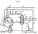
- the filters further have a receiving device 3 for receiving the scraped-off filter cake material and discharge thereof through the conduit 4 by means of a pump 5, and, as is shown in Figs. 3 and 4, a washing device 6 for washing of the filter cloth.
- the filter vessel has an inlet 7 for supplying the liquid to be filtrated and to keep the liquid at a certain level 8 in the vessel.
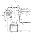
- filtrate and gas obtained at filtration are discharged through a conduit 9 to a separator 10, whereas in the embodiment according to Fig. 4 by the arrangement of intermediate walls 11 in the center shaft 2 is obtained on one hand a prefiltrate when the filter discs pass through the liquid, said prefiltrate being discharged to a filtrate tank 12 through a conduit 13, and on the other hand a clear filtrate discharged to said filtrate tank through conduit 14 and when the filter discs pass through the space above the liquid level filtrate, washing liquid and gas discharged through conduit 15 to the separator 10.
- blower 19 being adapted to generate a lower pressure in the inner of the filter discs and the blower 20 being adapted to generate an overpressure in the gas space of vessel 1 above the liquid level 8.
- blowers 19, 20 constitute examples of means for obtaining the pressure difference necessary for filtration between the gas space of the vessel and the interior of the filter discs by an overpressure in the gas space of the vessel and a lower pressure in the interior of the filter discs.
- a filter having advantages only obtained in a pressure filter as well as advantages only obtained in, for instance, a vacuum filter.
- a substantially cheaper filtration vessel can be utilized.
- a faster pressurizing of the filter is enabled.
- a valve 21 is located between the blowers 19 and 20, and after the blower 20 a valve 22.
- the valve 21 is adapted to provide a pressure of substantially zero between the blowers, and the valve 22 is adapted to ensure that an excessively high pressure is not obtained in the gas space of vessel 1.
- a conduit 23 is lead from a point between blowers 19 and 20 to the space of the filtrate tank 12 above its liquid level 24, said space being ventilated to the surrounding atmosphere through conduit 25.
- Overpressure and lower pressure can be varied in adaption to the present filtration case.
- the lower pressure shall be adapted to the temperature of the filtrate in the separator 10 in order to hereby enable an optimum boiling effect of the liquid.
- the overpressure shall be adapted to the lower pressure such that a pressure difference over the filter element necessary and suitable for filtration is obtained.
- the pressure difference may be 1.0 bar
- the overpressure in the gas space of vessel 1 then may be for instance between the limits 0.1 - 0.9 bar and the lower pressure in the interior of the filter discs between 0.9 - 0.1 bar.
- the separator 10 is provided with a cooling device 26, in this embodiment a device cooled by cooling water, said cooling water being introduced through conduit 27 and being discharged through conduit 28 provided with valve 29.
- the condensate obtained at cooling is discharged through conduit 30.
- FIGs. 3 and 4 Another substantial novelty of a filter according to one embodiment of the present invention is shown in Figs. 3 and 4.
- This novelty comprises an improved washing device referred to in Figs. 3 and 4 with numeral 6.
- the washing device is divided in at least two separate washing means 6, for instance spraying tubes, for washing in at least two steps.
- At washing in the second step occurs an advantageous stirring of the material deposited on the outside of the filter discs involving a better filtration than in previously known embodiments having only one washing means.
- the location of the washing means 6, as well as the location of the device 3 for receiving the scraped-off filter cake material is depending on the rotational direction of the filter discs.
- Washing liquid for the washing means can either be supplied from outside, for instance as is shown, only to the first washing means 6 through conduit 31 having a valve 32, or, may condensate from the separator 10 be supplied to a washing means, for instance as is shown through conduit 33 to the second washing means 6, in this case a pump 34 being inserted in condensate conduit 30 and a valve 35 being inserted in conduit 33.
- drum filters i.e. a filter element in the shape of a rotating drum having a surrounding filter cloth.
Landscapes
- Chemical & Material Sciences (AREA)
- Chemical Kinetics & Catalysis (AREA)
- Filtration Of Liquid (AREA)
- Vaporization, Distillation, Condensation, Sublimation, And Cold Traps (AREA)
- Glass Compositions (AREA)
- Separation Using Semi-Permeable Membranes (AREA)
- Separation By Low-Temperature Treatments (AREA)
- Cigarettes, Filters, And Manufacturing Of Filters (AREA)
Abstract
Description
- The present invention concerns a filter for continuous filtration of a liquid by means of at least one filter element particularly but not exclusively adapted to be used as a filter in a causticising process.
- According to the present invention a filter as claimed in claim 1 is provided. In US-A-4 695 381 (SE-B-451 948) a filter with the features of the preamble of claim 1 is disclosed.
- According to the present invention, by providing the means for pressurizing and the separator with said cooling device and the outlet means for condensate a row of advantages is achieved as compared to filters according to previously known art. Thus, a higher concentration of filtrated liquid (filtrate) is enabled in that a substantial part of the washing liquid (water) supplied for the above mentioned washing, otherwise diluting the filtrated liquid, is withdrawn by the condensation. Further, an improved separation of vapour in condensate and gas is obtained involving the advantage that a smaller amount of gas has to be added to the filter system which in turn involves the advantage of less risk of oxidation in the system of the medium passing through the filter system. In certain cases condensate can be brought back to the washing device which thus means it would not be necessary to supply washing liquid and also may result in a simplified structure. Further, a higher capacity is enabled in that a higher revolutionary speed of the filter element is possible.
- Summing up, as the most essential advantages of the present invention are enabled optimum expelling of gas from the filtrated liquid and also an optimum expelling of washing liquid.
- In one embodiment of the present invention there is also suitably provided a conduit between the gas space of the separator and the gas space of the vessel for recirculating gas to the gas space of the vessel, in said gas conduit being provided said means for generating said overpressure and said lower pressure. This results in a simple embodiment for obtaining said overpressure and said lower pressure and also a simple realization for adaption therebetween, especially when in a development of this embodiment said pressure generating means is divided in at least two pressure generating means separated along the gas conduit, at least said means provided closest to the separator generating said lower pressure in said space within said filter element and a subsequent means increasing the pressure for obtaining the overpressure existing in the gas space of the vessel. In this last mentioned embodiment prevailing atmospheric pressure may be preferably at a point between said pressure generating means for obtaining said lower pressure and said overpressure, respectively. To the higher concentration of filtrated liquid contributes also a preferred embodiment wherein the filter element comprises at least one disc element mounted on a substantially horizontal shaft and wherein said washing device is arranged for washing only of a zone of the disc element located closest to the shaft substantially concentric relative thereto and wherein said lower pressure at least substantially solely prevails over said washing zone.
- In a further preferred embodiment of the present invention the washing device is parted in at least two separated washing means for washing in at least two steps, whereby occurs an advantageous stirring of the material deposited on the outside of the filter element at the washing in the second step involving a better filtration than in embodiments according to known art having only one washing means.
- The above mentioned and other advantages of the present invention will be apparent from the following description of embodiments of filters according to the present invention, reference being made to the annexed drawings, wherein Fig. 1 - 4 schematically illustrate the examplified filters for illustrating elements of the invention and the function of the filters.
- The filters shown in the drawing which in these embodiments are so-called disc filters, include like previously known disc filters a substantially cylindrical vessel 1, a
center shaft 2 rotatably journal led in the vessel and a number of filter discs (not shown) arranged on the center shaft spaced from from each other, as is for instance shown in US-A-4 695 381. Each filter disc is composed of a number of disc sectors (not shown), for instance formed as is shown in US-A-4 695 381, said filter sectors in a conventional manner being composed of surrounding filter clothes and internal channels and being connected to the center shaft for discharging therethrough of filtrate and gas resulting from the filtration. The center shaft may be formed with a number of axial channels, one channel for each filter sector, as is described and shown in the above mentioned US-A-4 695 381, or may comprise one single channel common for filtrate and gas from all filter sectors of the pressure vessel as is shown in WO-A-9 010 490 (SE-B-463 601); both not pre-published. Further, as is shown in said WO-A-9 010 490, the filters may include a removing device or scraper for removal of filter cake deposited on the filter cloth at filtration and a device for removing filter cake material from the cloth located inside scraped off material, so-called precoat layer. As is shown in for instance Figs. 1 and 3 the filters further have a receiving device 3 for receiving the scraped-off filter cake material and discharge thereof through the conduit 4 by means of apump 5, and, as is shown in Figs. 3 and 4, awashing device 6 for washing of the filter cloth. Further, the filter vessel has aninlet 7 for supplying the liquid to be filtrated and to keep the liquid at acertain level 8 in the vessel. - As is shown in Figs. 1 - 3 filtrate and gas obtained at filtration are discharged through a conduit 9 to a
separator 10, whereas in the embodiment according to Fig. 4 by the arrangement of intermediate walls 11 in thecenter shaft 2 is obtained on one hand a prefiltrate when the filter discs pass through the liquid, said prefiltrate being discharged to afiltrate tank 12 through aconduit 13, and on the other hand a clear filtrate discharged to said filtrate tank throughconduit 14 and when the filter discs pass through the space above the liquid level filtrate, washing liquid and gas discharged throughconduit 15 to theseparator 10. - In the
separator 10 filtrate and gas are separated, the filtrate being discharged throughconduit 16 by means ofpump 17 and the gas being recirculated throughconduit 18 to the vessel 1. - In the
gas conduit 18 are arranged twoblowers blower 19 being adapted to generate a lower pressure in the inner of the filter discs and theblower 20 being adapted to generate an overpressure in the gas space of vessel 1 above theliquid level 8. Theseblowers - As appears from Figs. 1 - 3 a
valve 21 is located between theblowers valve 22. Thevalve 21 is adapted to provide a pressure of substantially zero between the blowers, and thevalve 22 is adapted to ensure that an excessively high pressure is not obtained in the gas space of vessel 1. In the embodiment of Fig. 4 aconduit 23 is lead from a point betweenblowers filtrate tank 12 above itsliquid level 24, said space being ventilated to the surrounding atmosphere throughconduit 25. Overpressure and lower pressure can be varied in adaption to the present filtration case. The lower pressure shall be adapted to the temperature of the filtrate in theseparator 10 in order to hereby enable an optimum boiling effect of the liquid. The overpressure shall be adapted to the lower pressure such that a pressure difference over the filter element necessary and suitable for filtration is obtained. For instance, at white liquor filtration the pressure difference may be 1.0 bar, the overpressure in the gas space of vessel 1 then may be for instance between the limits 0.1 - 0.9 bar and the lower pressure in the interior of the filter discs between 0.9 - 0.1 bar. - As appears from the figures, the
separator 10 is provided with acooling device 26, in this embodiment a device cooled by cooling water, said cooling water being introduced throughconduit 27 and being discharged throughconduit 28 provided withvalve 29. The condensate obtained at cooling is discharged throughconduit 30. - Another substantial novelty of a filter according to one embodiment of the present invention is shown in Figs. 3 and 4. This novelty comprises an improved washing device referred to in Figs. 3 and 4 with
numeral 6. The washing device is divided in at least two separate washing means 6, for instance spraying tubes, for washing in at least two steps. At washing in the second step occurs an advantageous stirring of the material deposited on the outside of the filter discs involving a better filtration than in previously known embodiments having only one washing means. As also appears from Figs. 3 and 4, the location of the washing means 6, as well as the location of the device 3 for receiving the scraped-off filter cake material, is depending on the rotational direction of the filter discs. Washing liquid for the washing means can either be supplied from outside, for instance as is shown, only to the first washing means 6 throughconduit 31 having avalve 32, or, may condensate from theseparator 10 be supplied to a washing means, for instance as is shown throughconduit 33 to the second washing means 6, in this case apump 34 being inserted incondensate conduit 30 and avalve 35 being inserted inconduit 33. - Hereinabove have been described and on the drawing have been shown disc filters. However, the invention may also concern drum filters, i.e. a filter element in the shape of a rotating drum having a surrounding filter cloth.
Claims (8)
- Filter for continuous filtration of a liquid under pressure, including a vessel (1) containing said liquid to a certain level and gas in a space located above said liquid, at least one rotatable filter element provided in said vessel and defining an inner space for filtrated liquid obtained by filtration, a washing device (6) for washing of material separated from the liquid and deposited on said filter element, communication between said inner space of said filter element and outlet means from said vessel for discharging the filtrated liquid and gas brought along therewith, a separator (10) connected to said outlet for separating the filtrated liquid and the accompanying gas, means (19,20)
for providing the pressure difference between the gas space of the vessel and the inner space of the filter element necessary for filtration, said means (19,20) being provided outside said vessel for generating an overpressure in the gas space of the vessel (1) and a lower pressure in the internal space of said filter element,
and a conduit (18) arranged between the gas space of the separator (10) and the gas space of the vessel (1) for recirculating gas to the gas space of the vessel, in said gas conduit (18) being provided said means (19,20) for providing the pressure difference, characterized in that
said means (19,20) is arranged to generate such a lower pressure that the filtrated liquid is maintained in a state of evaporation within the separator, and that said lower pressure is adapted to the temperature of the filtrate in the separator (10) in order to enable a boiling effect of the liquid, and
that the separator (10) is provided with a cooling device (26) for cooling the separated gas and with outlet means (30) for discharging condensate obtained by cooling. - Filter according to claim 1, characterized in that said overpressure and said lower pressure have substantially the same value.
- Filter according to claim 1 or 2, characterized in that said means (19,20) for providing the pressure difference is divided in at least two means separated along said gas conduit (18), at least said means arranged closest to the separator (10) generating said lower pressure in said space within said filter element and the subsequent means (20) increasing the pressure for obtaining the overpressure prevailing in the gas space of the vessel (1).
- Filter according to claim 3, characterized in that the pressure generating means are arranged such that atmospheric pressure is prevailing at a point between said means (19,20) for providing the pressure difference for obtaining said lower pressure and said overpressure, respectively.
- Filter according to any one of the preceding claims, wherein said filter element comprises at least one disc filter mounted on a substantially horizontal shaft, characterized in that said washing device (6) is adapted for washing of only one zone of the disc filter located closest to said shaft substantially concentrically relative thereto, said lower pressure prevailing at least substantially over said washing zone.
- Filter according to any one of the preceding claims, characterized in that said washing device (6) is divided in at least two separated washing means for washing in at least two steps.
- Filter according to any one of the preceding claims, characterized in that at least a part of the condensate obtained by cooling in said separator (10) is recirculated to the washing device.
- Filter according to any one of the preceding claims, characterized in that said means (19,20) for providing the pressure difference comprise blowers.
Applications Claiming Priority (3)
| Application Number | Priority Date | Filing Date | Title |
|---|---|---|---|
| SE8902147 | 1989-06-14 | ||
| SE8902147A SE464390B (en) | 1989-06-14 | 1989-06-14 | FILTER FOR CONTINUOUS FILTERING |
| PCT/SE1990/000413 WO1990015655A1 (en) | 1989-06-14 | 1990-06-13 | Filter for continuous filtration |
Publications (2)
| Publication Number | Publication Date |
|---|---|
| EP0473722A1 EP0473722A1 (en) | 1992-03-11 |
| EP0473722B1 true EP0473722B1 (en) | 1994-11-09 |
Family
ID=20376280
Family Applications (1)
| Application Number | Title | Priority Date | Filing Date |
|---|---|---|---|
| EP90909821A Expired - Lifetime EP0473722B1 (en) | 1989-06-14 | 1990-06-13 | Filter for continuous filtration |
Country Status (10)
| Country | Link |
|---|---|
| US (1) | US5151176A (en) |
| EP (1) | EP0473722B1 (en) |
| JP (1) | JPH0669523B2 (en) |
| AT (1) | ATE113858T1 (en) |
| CA (1) | CA2033982C (en) |
| DE (1) | DE69014114D1 (en) |
| ES (1) | ES2063363T3 (en) |
| FI (1) | FI92803C (en) |
| SE (1) | SE464390B (en) |
| WO (1) | WO1990015655A1 (en) |
Cited By (1)
| Publication number | Priority date | Publication date | Assignee | Title |
|---|---|---|---|---|
| WO2018186795A1 (en) * | 2017-04-07 | 2018-10-11 | Valmet Ab | Pressurized disc filter for causticization liquors containing lime mud |
Families Citing this family (11)
| Publication number | Priority date | Publication date | Assignee | Title |
|---|---|---|---|---|
| AT398389B (en) * | 1992-11-06 | 1994-11-25 | Andritz Patentverwaltung | METHOD AND SYSTEM FOR SEPARATING SOLID / LIQUID MIXTURES |
| US5302300A (en) * | 1993-04-05 | 1994-04-12 | Ingersoll-Rand Company | Method and apparatus for separating water from a condensate mixture in a compressed air system |
| US6063294A (en) * | 1996-10-15 | 2000-05-16 | Baker Hughes Incorporated | Uniform area shower for disc filter |
| SE516246C2 (en) * | 2001-02-07 | 2001-12-10 | Kvaerner Pulping Tech | Pipe system for receiving and transporting mesa from a white liquor filter |
| SE526706C2 (en) * | 2004-04-16 | 2005-10-25 | Kvaerner Pulping Tech | Method and apparatus for washing mesa |
| SE0401358L (en) * | 2004-05-26 | 2005-02-22 | Kvaerner Pulping Tech | Method and device for cleaning filters |
| FI20041518A (en) * | 2004-11-25 | 2006-05-26 | Andritz Oy | Method and apparatus for treating mesa |
| SE530768C2 (en) | 2007-12-06 | 2008-09-09 | Metso Fiber Karlstad Ab | System for receiving and transporting mesa from a white liquor filter |
| EP2522413A1 (en) * | 2011-05-10 | 2012-11-14 | Siemens Aktiengesellschaft | Filter device, method for its operation and usage |
| CN103801138B (en) * | 2014-01-28 | 2016-03-16 | 内蒙古蒙西鄂尔多斯铝业有限公司 | A kind of method and apparatus of calcium silicate slag quick separating |
| CN110075572B (en) * | 2019-05-24 | 2021-07-20 | 北京首钢朗泽新能源科技有限公司 | System and method for removing gas in feed liquid |
Family Cites Families (4)
| Publication number | Priority date | Publication date | Assignee | Title |
|---|---|---|---|---|
| US4120787A (en) * | 1976-12-29 | 1978-10-17 | United Technologies Corporation | Fuel cell water conditioning process and system and deaerator for use therein |
| SE451948B (en) * | 1985-05-02 | 1987-11-09 | Hedemora Ab | FILTER FOR CONTINUOUS FILTERING UNDER PRESSURE OF A SUSPENSION |
| FR2597362B1 (en) * | 1986-04-22 | 1991-07-26 | Guinard Oil Services | METHOD AND INSTALLATION FOR SEPARATING THE CONSTITUENTS OF A SUSPENSION. |
| US4775484A (en) * | 1987-03-09 | 1988-10-04 | Life Systems, Inc. | Method and apparatus for the continuous separation of contaminants from a fluid mixture |
-
1989
- 1989-06-14 SE SE8902147A patent/SE464390B/en not_active IP Right Cessation
-
1990
- 1990-06-13 ES ES90909821T patent/ES2063363T3/en not_active Expired - Lifetime
- 1990-06-13 CA CA002033982A patent/CA2033982C/en not_active Expired - Lifetime
- 1990-06-13 JP JP2509073A patent/JPH0669523B2/en not_active Expired - Lifetime
- 1990-06-13 DE DE69014114T patent/DE69014114D1/en not_active Expired - Lifetime
- 1990-06-13 US US07/655,395 patent/US5151176A/en not_active Expired - Lifetime
- 1990-06-13 AT AT90909821T patent/ATE113858T1/en not_active IP Right Cessation
- 1990-06-13 WO PCT/SE1990/000413 patent/WO1990015655A1/en active IP Right Grant
- 1990-06-13 EP EP90909821A patent/EP0473722B1/en not_active Expired - Lifetime
-
1991
- 1991-02-12 FI FI910666A patent/FI92803C/en active
Cited By (1)
| Publication number | Priority date | Publication date | Assignee | Title |
|---|---|---|---|---|
| WO2018186795A1 (en) * | 2017-04-07 | 2018-10-11 | Valmet Ab | Pressurized disc filter for causticization liquors containing lime mud |
Also Published As
| Publication number | Publication date |
|---|---|
| WO1990015655A1 (en) | 1990-12-27 |
| JPH04501980A (en) | 1992-04-09 |
| EP0473722A1 (en) | 1992-03-11 |
| SE8902147L (en) | 1990-12-15 |
| SE8902147D0 (en) | 1989-06-14 |
| DE69014114D1 (en) | 1994-12-15 |
| US5151176A (en) | 1992-09-29 |
| CA2033982A1 (en) | 1990-12-15 |
| JPH0669523B2 (en) | 1994-09-07 |
| ES2063363T3 (en) | 1995-01-01 |
| FI910666A0 (en) | 1991-02-12 |
| FI92803C (en) | 1995-01-10 |
| FI92803B (en) | 1994-09-30 |
| SE464390B (en) | 1991-04-22 |
| ATE113858T1 (en) | 1994-11-15 |
| CA2033982C (en) | 2000-11-28 |
Similar Documents
| Publication | Publication Date | Title |
|---|---|---|
| EP0473722B1 (en) | Filter for continuous filtration | |
| CA1098046A (en) | Apparatus and method for filtering a fibrous material with a disc filter | |
| SE463771B (en) | DEVICE AND PROCEDURE BEFORE SEPARATION OF WHEEL, MESA AND ANY SLAM WHEN USING A ROTATING DISC OR DRUM FILTER | |
| US4056473A (en) | Rotary filter for concentrating fiber suspensions | |
| US8002994B2 (en) | Method and apparatus for thickening lime mud in a disc filter | |
| FI94839C (en) | Device for filtration of sludge and method of use of the devices | |
| EP0239312A1 (en) | Method and apparatus for washing pulp | |
| EP0509561B1 (en) | Method and apparatus for treating fiber suspension | |
| CA2124041A1 (en) | Method and apparatus for recovering crystals from slurry | |
| SE501068C2 (en) | Method and apparatus for filtering a suspension | |
| US4956102A (en) | Method for operating rotating cylindrical filters and a rotatable cylindrical filter | |
| CA1229802A (en) | Rotatable filter assembly | |
| US2802572A (en) | Screen unit for treating solid matter of a suspension | |
| FI81725B (en) | FOERFARANDE OCH ANORDNING FOER BEHANDLING AV FIBERSUSPENSION. | |
| US5192454A (en) | Method for treating fiber suspension | |
| AU632557B2 (en) | Filter for continuous filtration | |
| EP0484342B1 (en) | Filter cylinder | |
| RU2018352C1 (en) | Continuous filter | |
| RU2091125C1 (en) | Filter-drier | |
| JP2539234Y2 (en) | Filter cylinder for filtration machine | |
| EP0094994B1 (en) | Improved rotary drum filter | |
| GB2120567A (en) | Rotary drum filter | |
| JPS58210812A (en) | Rotary drum type filter | |
| JPH0522591U (en) | Suction valve for filter |
Legal Events
| Date | Code | Title | Description |
|---|---|---|---|
| PUAI | Public reference made under article 153(3) epc to a published international application that has entered the european phase |
Free format text: ORIGINAL CODE: 0009012 |
|
| 17P | Request for examination filed |
Effective date: 19910205 |
|
| AK | Designated contracting states |
Kind code of ref document: A1 Designated state(s): AT BE CH DE DK ES FR GB IT LI LU NL |
|
| 17Q | First examination report despatched |
Effective date: 19930408 |
|
| RAP1 | Party data changed (applicant data changed or rights of an application transferred) |
Owner name: CAUSTEC AB |
|
| GRAA | (expected) grant |
Free format text: ORIGINAL CODE: 0009210 |
|
| AK | Designated contracting states |
Kind code of ref document: B1 Designated state(s): AT BE CH DE DK ES FR GB IT LI LU NL |
|
| PG25 | Lapsed in a contracting state [announced via postgrant information from national office to epo] |
Ref country code: IT Free format text: LAPSE BECAUSE OF FAILURE TO SUBMIT A TRANSLATION OF THE DESCRIPTION OR TO PAY THE FEE WITHIN THE PRESCRIBED TIME-LIMIT;WARNING: LAPSES OF ITALIAN PATENTS WITH EFFECTIVE DATE BEFORE 2007 MAY HAVE OCCURRED AT ANY TIME BEFORE 2007. THE CORRECT EFFECTIVE DATE MAY BE DIFFERENT FROM THE ONE RECORDED. Effective date: 19941109 Ref country code: NL Effective date: 19941109 Ref country code: LI Effective date: 19941109 Ref country code: CH Effective date: 19941109 Ref country code: DK Effective date: 19941109 Ref country code: BE Effective date: 19941109 |
|
| REF | Corresponds to: |
Ref document number: 113858 Country of ref document: AT Date of ref document: 19941115 Kind code of ref document: T |
|
| REF | Corresponds to: |
Ref document number: 69014114 Country of ref document: DE Date of ref document: 19941215 |
|
| ET | Fr: translation filed | ||
| REG | Reference to a national code |
Ref country code: ES Ref legal event code: FG2A Ref document number: 2063363 Country of ref document: ES Kind code of ref document: T3 |
|
| PG25 | Lapsed in a contracting state [announced via postgrant information from national office to epo] |
Ref country code: DE Effective date: 19950210 |
|
| REG | Reference to a national code |
Ref country code: CH Ref legal event code: PL |
|
| NLV1 | Nl: lapsed or annulled due to failure to fulfill the requirements of art. 29p and 29m of the patents act | ||
| PG25 | Lapsed in a contracting state [announced via postgrant information from national office to epo] |
Ref country code: GB Effective date: 19950613 |
|
| PG25 | Lapsed in a contracting state [announced via postgrant information from national office to epo] |
Ref country code: LU Free format text: LAPSE BECAUSE OF NON-PAYMENT OF DUE FEES Effective date: 19950630 |
|
| PLBE | No opposition filed within time limit |
Free format text: ORIGINAL CODE: 0009261 |
|
| STAA | Information on the status of an ep patent application or granted ep patent |
Free format text: STATUS: NO OPPOSITION FILED WITHIN TIME LIMIT |
|
| 26N | No opposition filed | ||
| GBPC | Gb: european patent ceased through non-payment of renewal fee |
Effective date: 19950613 |
|
| PGFP | Annual fee paid to national office [announced via postgrant information from national office to epo] |
Ref country code: FR Payment date: 19980511 Year of fee payment: 9 |
|
| PGFP | Annual fee paid to national office [announced via postgrant information from national office to epo] |
Ref country code: AT Payment date: 19980514 Year of fee payment: 9 |
|
| PGFP | Annual fee paid to national office [announced via postgrant information from national office to epo] |
Ref country code: ES Payment date: 19980616 Year of fee payment: 9 |
|
| PG25 | Lapsed in a contracting state [announced via postgrant information from national office to epo] |
Ref country code: AT Free format text: LAPSE BECAUSE OF NON-PAYMENT OF DUE FEES Effective date: 19990613 |
|
| PG25 | Lapsed in a contracting state [announced via postgrant information from national office to epo] |
Ref country code: ES Free format text: LAPSE BECAUSE OF EXPIRATION OF PROTECTION Effective date: 19990614 |
|
| PG25 | Lapsed in a contracting state [announced via postgrant information from national office to epo] |
Ref country code: FR Free format text: THE PATENT HAS BEEN ANNULLED BY A DECISION OF A NATIONAL AUTHORITY Effective date: 19990630 |
|
| REG | Reference to a national code |
Ref country code: FR Ref legal event code: ST |
|
| REG | Reference to a national code |
Ref country code: ES Ref legal event code: FD2A Effective date: 20010601 |