EP0473674B1 - Beam splitter for splitting an optical beam path - Google Patents
Beam splitter for splitting an optical beam path Download PDFInfo
- Publication number
- EP0473674B1 EP0473674B1 EP90908469A EP90908469A EP0473674B1 EP 0473674 B1 EP0473674 B1 EP 0473674B1 EP 90908469 A EP90908469 A EP 90908469A EP 90908469 A EP90908469 A EP 90908469A EP 0473674 B1 EP0473674 B1 EP 0473674B1
- Authority
- EP
- European Patent Office
- Prior art keywords
- beam splitter
- image
- viewfinder
- beam path
- area
- Prior art date
- Legal status (The legal status is an assumption and is not a legal conclusion. Google has not performed a legal analysis and makes no representation as to the accuracy of the status listed.)
- Expired - Lifetime
Links
Images


Classifications
-
- H—ELECTRICITY
- H04—ELECTRIC COMMUNICATION TECHNIQUE
- H04N—PICTORIAL COMMUNICATION, e.g. TELEVISION
- H04N5/00—Details of television systems
- H04N5/222—Studio circuitry; Studio devices; Studio equipment
- H04N5/2228—Video assist systems used in motion picture production, e.g. video cameras connected to viewfinders of motion picture cameras or related video signal processing
-
- G—PHYSICS
- G02—OPTICS
- G02B—OPTICAL ELEMENTS, SYSTEMS OR APPARATUS
- G02B27/00—Optical systems or apparatus not provided for by any of the groups G02B1/00 - G02B26/00, G02B30/00
- G02B27/10—Beam splitting or combining systems
- G02B27/14—Beam splitting or combining systems operating by reflection only
- G02B27/143—Beam splitting or combining systems operating by reflection only using macroscopically faceted or segmented reflective surfaces
-
- G—PHYSICS
- G02—OPTICS
- G02B—OPTICAL ELEMENTS, SYSTEMS OR APPARATUS
- G02B27/00—Optical systems or apparatus not provided for by any of the groups G02B1/00 - G02B26/00, G02B30/00
- G02B27/10—Beam splitting or combining systems
- G02B27/14—Beam splitting or combining systems operating by reflection only
- G02B27/144—Beam splitting or combining systems operating by reflection only using partially transparent surfaces without spectral selectivity
Definitions
- the invention relates to a beam splitter for splitting an optical beam path according to the preamble of claim 1.
- Beam splitters are widely used in optical devices and are used to split an incident beam path in at least two emerging partial beam paths that are forwarded to several independent optical systems.
- the exposure of the film material takes place through the recording beam path that enters the camera through the recording lens, from which a viewfinder beam path is deflected by a rotating mirror diaphragm during film transport and is directed by the cameraman into a viewfinder arrangement with an eyepiece for image control.
- a beam splitter is arranged in the viewfinder beam path, which splits off part of the viewfinder beam path and guides it into a video recording device.
- a camera is known in which a partially reflecting mirror is aligned in the recording beam path to reflect a television image to be recorded by a television camera.
- This partially reflecting mirror works on the principle of "physical division” and causes some of the rays incident in the camera to reach the viewfinder arrangement of the camera and the rest to the television camera connected to the camera.
- the cameraman takes the viewfinder image generated in the viewfinder image plane is only true with greatly reduced brightness through the eyepiece. This can lead to errors in the determination of the recorded image section, particularly in the case of poorly illuminated recording objects or low ambient brightness.
- the "geometric division" of the finder beam path is such that two concentric mirror surfaces are arranged in the finder beam path, offset by 90 ° to one another, the inner mirror surface passing part of the rays incident along the finder beam path into the eyepiece and the outer mirror surface the rest of the beam portion leads to the video camera.
- the two mirrors which are offset from one another accordingly make a geometrical division of the beam cross section incident in the viewfinder arrangement.
- the eye pupil when viewing the viewfinder image is only as large as the inner mirror surface, so that the full viewfinder image is only captured from a central perspective in the viewfinder, while only a part of the viewpoint from a lateral angle Viewfinder image is captured.
- the central decoupling of part of the beam path means a considerable loss of brightness in the middle of the image.
- a viewfinder arrangement for a recording camera in which the beam path incident through the recording optics is directed alternately through a mirror reflex device onto a film to be exposed or the viewfinder arrangement.
- a focusing screen is arranged in the viewfinder beam path, the image of which can be viewed through a viewfinder eyepiece.
- An optical fade-in system is provided in the beam path between the focusing screen and the viewfinder eyepiece, which on the one hand allows the viewing of the focusing screen image through the viewfinder eyepiece and on the other hand the imaging of a focusing screen marking or a combination of several markings.
- the fade-in system consists of a semi-transparent mirror or a prism.
- the projection of the focusing screen marking onto the focusing screen is carried out by means of a projection device, which consists of a projection objective, a condenser and a light source as well as a parabolic mirror, using a still image.
- This still image consists of the negative image of the focusing screen marking or a combination of several focusing screen markings.
- a viewfinder system for cameras which has a focusing screen onto which an image of the scene to be recorded is projected as a function of the position of a rotary screen which is synchronized with the movement of the film.
- the focusing screen has a marking arrangement designed as a boundary line, which form two rectangular picture windows.
- a beam splitter is arranged in the viewfinder beam path, which enables the image projected onto the focusing screen to be viewed via an eyepiece arrangement.
- a light source arrangement is provided which illuminates the marking arrangement provided on the side of the focusing screen facing the beam splitter.
- an optical element designed as a converging lens which consists of two parts joined together on a joining surface.
- a beam splitter layer in the form of an ellipse is applied to the joint surface, while the remaining area of the joint surface carries an anti-reflective layer.
- the rays incident in the converging lens pass through the converging lens outside the beam splitter layer and are partially reflected on the beam splitter layer.
- the invention has for its object to provide a beam splitter which, with partial reflection of incident rays, enables a viewfinder image which is only insignificantly reduced in brightness compared to the recorded image of the camera and which is complete in the image detail even with a lateral view into the viewfinder eyepiece and in which the lighting is also unfavorable both the marking of the image field in the viewfinder window of an optical device and the object to be viewed remain visible.
- the invention is based on the idea that when generating a viewfinder image from a portion of the beam path incident in the beam splitter, it is particularly important to give the viewer of the viewfinder image a correct impression of the image section actually determined by the positioning of the taking lens and by means of a sufficient viewfinder image brightness to enable easy focusing and definition of the image section.
- the viewfinder image is characterized by a uniform brightness distribution
- the division according to the invention of the reflective coating of the beam splitter surface into an inner region and a partially reflecting outer region indicating the inner region makes it possible to split off a portion of the beam path corresponding to the reduced brightness of a partial region of the viewfinder image and to use it for other purposes, for example for reflecting video images, without that this would entail substantial losses in the quality of the viewfinder image.
- the viewfinder image that matches the image in its image section, there is no pupil effect of the beam splitter that restricts the possible viewing angle of the viewer into the eyepiece.
- This enables greater mobility when viewing the viewfinder image through the eyepiece, since the viewer's eye does not necessarily have to be aligned with the optical axis of the viewfinder arrangement in order to be able to perceive the viewfinder image.
- the inner region and the partially reflecting outer region of the reflective coating of the beam splitter are arranged concentrically to the point of intersection as the point of incidence of the optical axis of the incident beam path, the inner region having the contour of an ellipse oriented centrally to the point of penetration.
- the central arrangement of the inner area ensures that even when the viewfinder image is viewed offset or at an angle to the optical axis of the viewfinder arrangement, the brighter inner area of the viewfinder image suitable for focusing is perceived in any case.
- the interior can either be completely reflective or completely transparent.
- the choice depends on the arrangement of the viewfinder in relation to the imaging optics. If the viewfinder is arranged on the side of the beam splitter opposite to the recording optics, the inner region is made completely transparent be, while with the optical system and viewfinder arranged on the same side, a completely reflective inner region is selected. In this case, the beam path in the interior is deflected from the recording optics to the finder beam path.
- the elliptical design of the inner region means that the image of the surface of the inner region projected perpendicular to the finder beam path results in a circle due to the inclination of the beam splitter.
- the inner, bright image area of the viewfinder image is circular, so that with the aid of the circular viewfinder image area an exact alignment of the optical device, in particular a motion picture camera, with the object to be imaged is possible.
- the base body of the beam splitter is advantageously designed as a plane lens. This enables a particularly simple realization of the beam splitter.
- the outer area has a reflectance of 10% to 90%, the inner area being completely transparent.
- the non-reflective interior of the The beam splitter thus gives the viewer an overall sufficient impression of brightness of the viewfinder image. Accordingly, 90% to 10% of the amount of light incident in the outer region of the beam splitter remains for the partial beam path divided by the beam splitter.
- the outer region has a degree of reflection of 10% to 90%, the inner region being designed to be completely reflective.
- This embodiment is intended for motion picture cameras, the viewfinder and optics of which are arranged on the same side with respect to the beam splitter.
- FIG. 1 shows a schematic illustration of the optical system of the viewfinder arrangement 1 of a motion picture camera.
- a recording beam path 4 entering the camera through a taking lens 3 is divided into a film exposure component 6 and a finder beam path 7, 8, 9, 10, 14 via a rotating mirror diaphragm 5.
- the film exposure portion 6 strikes a film 13 to be exposed and guided in a film channel 12 through an image window 11.
- the finder beam path 7 first passes through a focusing screen or fiberboard 19, and then, as a finder beam path 8, is incident parallel to the finder beam path 7 through the deflection device 15 into a beam splitter 20.
- the finder beam path 9 is guided through a first imaging system 21 and after further deflection through the downstream deflection device 17 as a finder beam path 10 through a second imaging system 22.
- a further deflection device 23 which is designed as a mechanically rotatable compensation means in the form of a straight-line prism which prevents image rotation.
- the finder beam path 10 finally undergoes a final deflection through the deflection device 18 in order to pass through a faceplate 24 and finally an eyepiece 25 as the finder beam path 14.
- the eyepiece 25 makes it possible to view the viewfinder image 2 generated as an aerial image between the faceplate 24 and the eyepiece 25.
- the beam splitter 20 arranged in the finder beam path 8 between the deflection devices 15, 16 splits off a video beam path 26, 27, 28 from the finder beam path 8 in order to generate a video image in a video camera 29 connected to the motion picture SLR camera.
- the video beam path 26, 27, 28 shown in FIGS. 2 and 3 is passed through an imaging system 30 and two deflection devices 31, 32.
- the video camera 29 is connected to the motion picture camera via a flange connection 33.
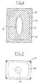
- the beam splitter 20 shown in a top view in FIG. 4 and arranged in the finder beam path 8 (FIG. 1) between the deflection devices 15 and 16 has two areas, namely an inner area 34 and an outer area 35, with different degrees of reflection.
- the inner region 34 and the outer region 35 are aligned concentrically with the optical axis passing through the beam splitter 20 or with the finder beam path 8.
- the outer region 35 is designed as a semipermeable mirror on a plane lens 37 serving as a base body.
- the inner region 34 is excluded from the mirroring applied, for example, by vapor deposition and allows the finder beam path 8 to pass uninterruptedly through the beam splitter 20, so that only the light beams passing through the outer region 35 are partially reflected and thus form the video beam path 26, 27, 28.
- the inner region 34 has an elliptical contour which, due to the 45 ° inclination of the beam splitter 20, becomes circular in the projection perpendicular to the finder beam path 8. Therefore, the center of the viewfinder image 2 perceptible through the eyepiece 25, which corresponds essentially to the image recorded in the image window 11, is formed as a circle.
- the viewfinder image 2 has different brightness areas for the viewer, which correspond in their distribution to the central inner area 34 and the outer area 35 surrounding them.
- the use of a beam splitter 20 provided with a non-reflecting inner region 34 and a 50% reflecting outer region 35 enables the viewer to easily and precisely focus and select the image section of the target object due to the brighter inner image region.
- the selected size ratio and the degree of reflection or transmittance of inner area 34 and outer area 35 is essentially dependent on the amount of light required for video image construction and image viewing.
- the eyepiece arrangement shown schematically in FIG. 5 can be used in any optical device for viewing an object to be imaged, preferably in a motion picture film recording camera.
- the object captured by the optical system is imaged as an aerial photograph or on a focusing screen in level 51.
- the recording optics is a rotating aperture downstream, which is synchronized with the film movement, so that an image of a scene to be recorded is alternately projected onto a film moved behind the rotating aperture or reflected onto the aerial picture plane 51.
- the eyepiece arrangement essentially consists of a beam splitter 20, a first field lens 54 arranged in the center of the viewfinder beam path 50 behind the aerial image plane 51, and a viewfinder eyepiece 60 arranged on the other side of the beam splitter 20, with which the image sharpness is focused on the aerial image plane 51.
- a light frame mask 52 contains, in positive or negative representation, a marking arrangement designed as boundary lines, which has an image window and possibly a hair cross for focusing.
- a diffusing screen 55 is provided behind the luminous frame mask 52, in which light-emitting diodes 58 arranged in a distributed manner or a concentric lighting device can be integrated.
- an illuminating device 56 or self-illuminating elements that can be activated by daylight, for example beta lights, can be arranged on the side of the diffusing screen 55 opposite the luminous frame mask 52.
- colored sheets 59 e.g. can be made of plastic, to be attached to the rear of the lens 55 in order to produce a correspondingly colored light frame when projected onto the beam splitter 20.
- the beam splitter 20 has a plurality of regions with different reflectance or transmittance for reflecting a part of the beam path into, for example, a video camera.
- the beam splitter 20 has an inner region 34 and an outer region 35 with different degrees of reflection or transmittance, the inner region 34 and the outer region 35 being aligned concentrically with the optical axis passing through the beam splitter 20 or with the finder beam path .
- the inner region 34 is optionally designed to be non-reflective or completely transparent or completely reflective. The choice depends on the arrangement of the viewfinder in relation to the imaging optics. If the viewfinder is arranged on the side of the beam splitter opposite to the recording optics, the interior will be made completely transparent, while if the recording optics and the viewfinder are arranged on the same side, a completely reflecting interior will be selected. In this case, the beam path in the interior is deflected from the recording optics to the finder beam path.
- the outer area 35 is partially reflective or partially permeable.
- the beam splitter 20 can be designed as a vaporized splitter mirror, the degree of reflection or transmittance of the mirror being determined by the degree of vaporization.
- the outer region 35 has, for example, a reflectance of 10%, so that 10% of the light projected from the light frame arrangement onto the beam splitter 20 is reflected in the direction of the finder eyepiece 60.
- 90% of the aerial image 51 imaged by means of the field lens 54 pass through the beam splitter 20 and are perceived by the viewer B via the viewfinder eyepiece 60.
- the different configurations of the individual areas of the beam splitter 20 can take place in such a way that the inner area 34 is covered during the manufacture of the beam splitter 20 and the outer area is vaporized depending on the desired degree of reflection. In the same way, further areas with different degrees of reflection or transmittance of the beam splitter 20 can be produced.
- the outer region 35 can be vaporized depending on the desired degree of reflection and then the inner region 34 can be completely vaporized during the manufacture of the beam splitter 20 in order to achieve a completely reflective inner region 34.
- the outer region 35 is a semi-permeable mirror on a base body serving plan lens.
- the inner region 34 is excluded from the mirroring applied, for example, by vapor deposition and allows the finder beam path to pass uninterruptedly through the beam splitter 20, so that only the light rays passing through the outer region 35 are partially reflected or transmitted to a desired percentage.
- the inner region 34 has an elliptical contour which, due to the 45 ° inclination of the beam splitter 20, becomes circular in the projection perpendicular to the finder beam path. Therefore, the center of the viewfinder image perceptible through the viewfinder eyepiece 60, which corresponds essentially to the image image generated in the image window, is designed as a circle.
- the viewfinder image has different brightness areas for the viewer, which correspond in their distribution to the central inner area 34 and the outer area 35 surrounding them.
- the use of a beam splitter 20 provided with a non-reflecting inner area 34 and a partially reflecting outer area 35 enables the viewer B to focus and select the image detail of the target object easily and precisely due to the brighter, inner image area.
- FIG. 6 shows the image of the light frame mask 52 on the partially reflecting outer area 35 of the beam splitter 20.
- FIG. 7 shows the projection of the illuminated frame mask 52 visible to the viewer B through the finder eyepiece 60 according to FIG. 1 onto a viewfinder image 51 visible through the finder eyepiece 60.
- the viewfinder image 51 has different brightness areas for the viewer, which correspond in their distribution to the central inner area 34 and the outer area 35 surrounding them.
- the inner region 34 which is provided with an elliptical contour, becomes a circular image region 62 in the viewfinder image 51.
- a beam splitter 20 provided with a non-reflecting inner region 34 and an outer region 35, for example a 10% reflective region, enables the viewer to focus and image observation and selection of the object field simply and precisely due to the brighter inner image region 62 according to FIG.
- the viewfinder image is superimposed on the illuminated frame mask to a desired extent, so that the viewer is precisely delimited even in very unfavorable lighting conditions.
- the measure The luminous intensity of the superimposed light frame mask depends on the one hand on the illumination of the light frame mask 52 according to FIG. 1 itself and on the degree of reflection of the outer area 35 of the beam splitter 20.
- the degree of brightness of the superimposed luminous frame arrangement can be changed by correspondingly varying the luminous intensity of the luminous elements.
- the desired degree of brightness can be set by covering the elements, for example by using a blind-like adjusting device.
- differently colored sheets of the diffusing screen 55 can be underlaid, so that a desired color of the displayed light frame can be selected.
- the embodiment of the invention is not limited to the preferred exemplary embodiment specified above. Rather, a number of variants are conceivable which make use of the solution shown, even in the case of fundamentally different types.
Abstract
Description
Die Erfindung betrifft einen Strahlenteiler zur Teilung eines optischen Strahlenganges gemäß dem Oberbegriff des Anspruchs 1.The invention relates to a beam splitter for splitting an optical beam path according to the preamble of claim 1.
Strahlenteiler werden vielfach in optischen Geräten eingesetzt und dienen der Aufteilung eines einfallenden Strahlengangs in mindestens zwei austretende Teilstrahlengänge, die an mehrere voneinander unabhängige optische Systeme weitergeleitet werden.Beam splitters are widely used in optical devices and are used to split an incident beam path in at least two emerging partial beam paths that are forwarded to several independent optical systems.
Bei Laufbild-Filmaufnahmekameras erfolgt die Belichtung des Filmmaterials durch den durch das Aufnahmeobjektiv in die Kamera einfallenden Aufnahmestrahlengang, von dem durch eine rotierende Spiegelblende ein Sucherstrahlengang während des Filmtransports umgelenkt und zur Bildkontrolle durch den Kameramann in eine Sucheranordnung mit Okular geleitet wird. Zur Ausspiegelung von Videobildern ist im Sucherstrahlengang ein Strahlenteiler angeordnet, der einen Teil des Sucherstrahlenganges abspaltet und in eine Videoaufnahmeeinrichtung leitet.In motion picture film recording cameras, the exposure of the film material takes place through the recording beam path that enters the camera through the recording lens, from which a viewfinder beam path is deflected by a rotating mirror diaphragm during film transport and is directed by the cameraman into a viewfinder arrangement with an eyepiece for image control. For reflecting video images, a beam splitter is arranged in the viewfinder beam path, which splits off part of the viewfinder beam path and guides it into a video recording device.
Dabei sind zur Bildausspiegelung zwei hinsichtlich ihrer Wirkungsweise unterschiedliche Möglichkeiten der Teilung des Sucherstrahlengangs bekannt, nämlich die sogenannte "physikalische Teilung" und die "geometrische Teilung".Two ways of dividing the viewfinder beam path with regard to their mode of operation are known for image reflection, namely the so-called “physical division” and the “geometric division”.
Aus der DE-PS 32 05 469 ist eine Kamera bekannt, bei der zur Auspiegelung eines von einer Fernsehkamera aufzunehmenden Fernsehbildes ein teilweise reflektierender Spiegel im Aufnahmestrahlengang ausgerichtet ist. Dieser teilweise reflektierende Spiegel arbeitet nach dem Prinzip der "physikalischen Teilung" und bewirkt, daß ein Teil der in die Kamera einfallenden Strählen zur Sucheranordnung der Kamera und der Rest in die mit der Kamera verbundene Fernsehkamera gelangt.From DE-PS 32 05 469 a camera is known in which a partially reflecting mirror is aligned in the recording beam path to reflect a television image to be recorded by a television camera. This partially reflecting mirror works on the principle of "physical division" and causes some of the rays incident in the camera to reach the viewfinder arrangement of the camera and the rest to the television camera connected to the camera.
Aufgrund der nach der Teilung verbleibenden, stark reduzierten Lichtmenge für die Sucheranordnung nimmt der Kameramann das in der Sucherbildebene erzeugte Sucherbild nur mit stark verminderter Helligkeit durch das Okular wahr. Dies kann besonders bei schlecht ausgeleuchteten Aufnahmeobjekten oder geringer Umgebungshelligkeit zu Fehlern bei der Bestimmung des Aufnahmebildausschnitts führen.Due to the greatly reduced amount of light remaining after the division for the viewfinder arrangement, the cameraman takes the viewfinder image generated in the viewfinder image plane is only true with greatly reduced brightness through the eyepiece. This can lead to errors in the determination of the recorded image section, particularly in the case of poorly illuminated recording objects or low ambient brightness.
Bei der "geometrischen Teilung" des Sucherstrahlenganges wird so verfahren, daß zwei konzentrische, zueinander um 90° versetzte Spiegelflächen im Sucherstrahlengang angeordnet sind, wobei die innere Spiegelfläche einen Teil der längs des Sucherstrahlengangs einfallenden Strahlen in das Okular weiterleitet und die äußere Spiegelfläche den übrigen Strahlenanteil zur Videokamera führt. Durch die beiden zueinander versetzten Spiegel wird demnach eine geometrische Aufteilung des in die Sucheranordnung einfallenden Strahlenquerschnitts vorgenommen.The "geometric division" of the finder beam path is such that two concentric mirror surfaces are arranged in the finder beam path, offset by 90 ° to one another, the inner mirror surface passing part of the rays incident along the finder beam path into the eyepiece and the outer mirror surface the rest of the beam portion leads to the video camera. The two mirrors which are offset from one another accordingly make a geometrical division of the beam cross section incident in the viewfinder arrangement.
Aufgrund der "geometrischen Teilung" des Sucherstrahlengangs ist die Augenpupille bei der Betrachtung des Sucherbilds nur so groß wie die innere Spiegelfläche, so daß das volle Sucherbild nur bei einem zentrischem Blickwinkel in den Sucher erfaßt wird, während bei einem seitlichen Blickwinkel nur jeweils ein Teil des Sucherbildes erfaßt wird. Für die Videokamera bedeutet jedoch das zentrische Auskoppeln eines Teils des Strahlengangs einen erheblichen Helligkeitsverlust in der Mitte des Bildes.Due to the "geometrical division" of the viewfinder beam path, the eye pupil when viewing the viewfinder image is only as large as the inner mirror surface, so that the full viewfinder image is only captured from a central perspective in the viewfinder, while only a part of the viewpoint from a lateral angle Viewfinder image is captured. For the video camera, however, the central decoupling of part of the beam path means a considerable loss of brightness in the middle of the image.
Aus der DE-OS 30 38 389 ist eine Sucheranordnung für eine Aufnahmekamera bekannt, bei welcher der durch die Aufnahmeoptik einfallende Strahlengang durch eine Spiegelreflexeinrichtung alternierend auf einen zu belichtenden Film oder die Sucheranordnung geleitet wird.From DE-OS 30 38 389 a viewfinder arrangement for a recording camera is known, in which the beam path incident through the recording optics is directed alternately through a mirror reflex device onto a film to be exposed or the viewfinder arrangement.
Im Sucherstrahlengang ist eine Mattscheibe angeordnet, deren Bild über ein Sucherokular betrachtet werden kann. Im Strahlengang zwischen der Mattscheibe und dem Sucherokular ist ein optisches Einblendsystem vorgesehen, das einerseits die Betrachtung des Mattscheibenbildes durch das Sucherokular und andererseits die Abbildung einer Mattscheibenmarkierung bzw. einer Kombination mehrerer Markierungen erlaubt.A focusing screen is arranged in the viewfinder beam path, the image of which can be viewed through a viewfinder eyepiece. An optical fade-in system is provided in the beam path between the focusing screen and the viewfinder eyepiece, which on the one hand allows the viewing of the focusing screen image through the viewfinder eyepiece and on the other hand the imaging of a focusing screen marking or a combination of several markings.
Das Einblendsystem besteht aus einem halbdurchlässigen Spiegel oder einem Prisma. Die Projektion der Mattscheibenmarkierung auf die Mattscheibe erfolgt mittels eines Projektionsgerätes, das aus einem Projektionsobjektiv, einem Kondensor und einer Lichtquelle sowie einem Parabolspiegel besteht, unter Verwendung eines Stehbildes. Dieses Stehbild besteht aus dem Negativbild der Mattscheibenmarkierung bzw. einer Kombination mehrerer Mattscheibenmarkierungen.The fade-in system consists of a semi-transparent mirror or a prism. The projection of the focusing screen marking onto the focusing screen is carried out by means of a projection device, which consists of a projection objective, a condenser and a light source as well as a parabolic mirror, using a still image. This still image consists of the negative image of the focusing screen marking or a combination of several focusing screen markings.
Durch die Verwendung eines halbdurchlässigen Spiegels oder eines Prismas als optisches Einblendsystem wird jedoch ein erheblicher Teil des durch die Aufnahmeoptik auf die Mattscheibe fallenden Lichtes des aufzunehmenden Objektes ausgeblendet, so daß eine Bildbetrachtung zur Fokussierung und Auswahl des Bildausschnittes insbesondere bei schlechten Lichtverhältnissen erheblich erschwert bzw. unmöglich gemacht wird. Zwar erlaubt die Projektion der Mattscheibenmarkierung auch bei schlechten Lichtverhältnissen eine exakte Festlegung des Bildausschnittes, jedoch verschwindet bei entsprechend schlechten Lichtverhältnissen das Bild selbst nahezu vollständig, so daß unter ungünstigen Bedingungen keine Aufnahmen möglich sind.Through the use of a semi-transparent mirror or a prism as an optical fade-in system, however, a considerable part of the light of the object to be captured, which is incident on the focusing screen through the optics, is masked out, so that viewing the image to focus and select the image detail, particularly in poor lighting conditions, is made considerably more difficult or impossible is made. Although the projection of the focusing screen marking allows an exact definition of the image section even in poor lighting conditions, the image itself almost completely disappears in poor lighting conditions, so that under unfavorable conditions no pictures are possible.
Aus der DE-PS 27 34 792 ist ein Suchersystem für Kameras bekannt, das eine Mattscheibe aufweist, auf die ein Abbild der aufzunehmenden Szene in Abhängigkeit von der Stellung einer Drehblende projiziert wird, die mit der Bewegung des Films synchronisiert ist. Die Mattscheibe weist eine als Umgrenzungslinie ausgebildete Markierungsanordnung auf, die zwei rechteckige Bildfenster ausbilden. Im Sucherstrahlengang ist ein Strahlenteiler angeordnet, der die Betrachtung des auf die Mattscheibe projizierten Bildes über eine Okularanordnung ermöglicht. Auf der anderen Seite des Strahlenteilers ist eine Lichtquellenanordnung vorgesehen, die durch den Strahlenteiler die auf der dem Strahlenteiler zugewandten Seite der Mattscheibe vorgesehene Markierungsanordnung beleuchtet.From DE-PS 27 34 792 a viewfinder system for cameras is known which has a focusing screen onto which an image of the scene to be recorded is projected as a function of the position of a rotary screen which is synchronized with the movement of the film. The focusing screen has a marking arrangement designed as a boundary line, which form two rectangular picture windows. A beam splitter is arranged in the viewfinder beam path, which enables the image projected onto the focusing screen to be viewed via an eyepiece arrangement. On the other side of the beam splitter, a light source arrangement is provided which illuminates the marking arrangement provided on the side of the focusing screen facing the beam splitter.
Auch bei dieser bekannten Sucheranordnung geht ein erheblicher Teil des nutzbaren Objektlichtes infolge der Verwendung eines halbdurchlässigen Strahlenteilers verloren, so daß unter ungünstigen Lichtverhältnissen zwar eine Beleuchtung der Markierungsanordnung der Mattscheibe gegeben ist, das auf die Mattscheibe projizierte Bild des aufzunehmenden Objekts jedoch nicht mehr erkennbar ist.In this known viewfinder arrangement, too, a considerable part of the usable object light is lost due to the use of a semitransparent beam splitter, so that although the marking arrangement of the focusing screen is illuminated under unfavorable lighting conditions, the image of the object to be recorded projected onto the focusing screen is no longer recognizable.
Aus der EP-A-0209108 ist ein als Sammellinse ausgebildetes optisches Element bekannt, das aus zwei an einer Fügefläche zusammengefügten Teilen besteht. Auf der Fügefläche ist eine Strahlenteilerschicht in Form einer Ellipse aufgebracht, während der verbleibende Bereich der Fügefläche eine Antireflexschicht trägt. Die in die Sammellinse einfallenden Strahlen gehen außerhalb der Strahlenteilerschicht durch die Sammellinse hindurch und werden an der Strahlenteilerschicht teilweise ausgespiegelt.From EP-A-0209108 an optical element designed as a converging lens is known, which consists of two parts joined together on a joining surface. A beam splitter layer in the form of an ellipse is applied to the joint surface, while the remaining area of the joint surface carries an anti-reflective layer. The rays incident in the converging lens pass through the converging lens outside the beam splitter layer and are partially reflected on the beam splitter layer.
Würde man ein derartiges optisches Element in den Strahlengang einer Filmaufnahmekamera anordnen, um einen Teil der einfallenden Strahlen zu einem Betrachtungsokular zu leiten und einen anderen Strahlenanteil zu einer Videokamera zu führen, so hätte dies zur Folge, daß bei Anordnung des Okulars im durchgehenden Stahlengang dem Betrachter gerade der wesentliche Mittenbereich abgedunkelt erscheint, da hier ein Teil der einfallenden Strahlen umgelenkt wird, während eine im ausgespiegelten Strahlengang angeordnete Videokamera nur den abgedunkelten Mittenbereich empfangen würde.If one arranged such an optical element in the beam path of a film recording camera in order to guide a part of the incident rays to a viewing eyepiece and to guide another part of the beam to a video camera, this would have the consequence that if the eyepiece was arranged in the continuous beam path, the viewer the essential central area appears to be darkened, since some of the incident rays are deflected here, whereas a video camera arranged in the mirrored beam path would only receive the darkened central area.
Würde umgekehrt das Okular im ausgespiegelten Strahlengang angeordnet, so könnte durch dieses nur der abgedunkelte Mittenbereich betrachtet werden, wobei bei einer Bewegung des Auges außerhalb des Mittenbereichs kein Bild mehr zu sehen wäre. Eine in diesem Fall im durchgehenden Strahlengang angeordnete Videokamera würde dementsprechend nur einen abgedunkelten Mittenbereich empfangen.Conversely, if the eyepiece were arranged in the reflected beam path, only the darkened central area could be viewed through it, with no movement of the eye outside the central area. A video camera arranged in the continuous beam path in this case would accordingly only receive a darkened central area.
Die aus der DE-C-3205469 bekannte Problematik läßt sich somit auch durch dieses bekannte optische Element nicht lösen.The problem known from DE-C-3205469 cannot be solved by this known optical element.
Der Erfindung liegt die Aufgabe zugrunde, einen Strahlenteiler zu schaffen, der bei einer Teilausspiegelung einfallender Strahlen ein gegenüber dem Aufnahmebild der Kamera in seiner Helligkeit nur unwesentlich reduziertes und im Bildausschnitt vollständiges Sucherbild auch bei seitlichem Einblick in das Sucherokular ermöglicht und bei dem auch bei ungünstigen Lichtverhältnissen sowohl die Markierung des Bildfeldes im Sucherfenster eines optischen Gerätes als auch das zu betrachtende Objekt sichtbar bleibt.The invention has for its object to provide a beam splitter which, with partial reflection of incident rays, enables a viewfinder image which is only insignificantly reduced in brightness compared to the recorded image of the camera and which is complete in the image detail even with a lateral view into the viewfinder eyepiece and in which the lighting is also unfavorable both the marking of the image field in the viewfinder window of an optical device and the object to be viewed remain visible.
Diese Aufgabe wird erfindungsgemäß durch das kennzeichnende Merkmal des Anspruchs 1 gelöst.This object is achieved by the characterizing feature of claim 1.
Der Erfindung liegt der Gedanke zugrunde, daß es bei der Erzeugung eines Sucherbildes aus einem Anteil des in den Strahlenteiler einfallenden Strahlengangs vor allem darauf ankommt, dem Betrachter des Sucherbildes einen korrekten Eindruck über den tatsächlich durch die Positionierung des Aufnahmeobjektivs bestimmten Bildausschnitts zu geben und durch eine genügende Sucherbildhelligkeit eine einfache Fokussierung und Festlegung des Bildausschnitts zu ermöglichen.The invention is based on the idea that when generating a viewfinder image from a portion of the beam path incident in the beam splitter, it is particularly important to give the viewer of the viewfinder image a correct impression of the image section actually determined by the positioning of the taking lens and by means of a sufficient viewfinder image brightness to enable easy focusing and definition of the image section.
Da es zur Fokussierung und Festlegung des Bildausschnitts jedoch nicht notwendig ist, daß sich das Sucherbild durch eine gleichmäßige Helligkeitsverteilung auszeichnet, sondern ausreichend ist, durch einen in seiner Helligkeit gegenüber dem Aufnahmebild im wesentlichen nicht reduzierten Teilbereich des Sucherbildes eine genaue Fokussierung und Bestimmung des Bildausschnitts zu ermöglichen.However, since it is not necessary for focusing and fixing the image section that the viewfinder image is characterized by a uniform brightness distribution, it is sufficient to precisely focus and determine the image section by a partial area of the viewfinder image that is essentially not reduced in brightness compared to the recorded image enable.
Die erfindungsgemäße Aufteilung der reflektierenden Beschichtung der Strahlenteilerfläche in-einen Innenbereich und einen den Innenbereich angebenden teilreflektierenden Außenbereich schafft die Möglichkeit, einen der reduzierten Helligkeit eines Teilbereichs des Sucherbildes entsprechenden Anteil des Strahlenganges abzuspalten und für andere Zwecke, beispielsweise zur Ausspiegelung von Videobildern zu benutzen, ohne daß hiermit wesentliche Einbußen in der Qualität des Sucherbildes verbunden wären.The division according to the invention of the reflective coating of the beam splitter surface into an inner region and a partially reflecting outer region indicating the inner region makes it possible to split off a portion of the beam path corresponding to the reduced brightness of a partial region of the viewfinder image and to use it for other purposes, for example for reflecting video images, without that this would entail substantial losses in the quality of the viewfinder image.
Vorteilhafterweise ergibt sich aufgrund des in seinem Bildausschnitt mit dem Aufnahmebild übereinstimmenden Sucherbildes keine, den möglichen Blickwinkel des Betrachters in das Okular einschränkende Pupillenwirkung des Strahlenteilers. Dies ermöglicht eine größere Mobilität bei der Betrachtung des Sucherbildes durch das Okular, da das Auge des Betrachters nicht unbedingt mit der optischen Achse der Sucheranordnung auszurichten ist, um das Sucherbild wahrnehmen zu können.Advantageously, due to the viewfinder image that matches the image in its image section, there is no pupil effect of the beam splitter that restricts the possible viewing angle of the viewer into the eyepiece. This enables greater mobility when viewing the viewfinder image through the eyepiece, since the viewer's eye does not necessarily have to be aligned with the optical axis of the viewfinder arrangement in order to be able to perceive the viewfinder image.
Nach einer vorteilhaften Weiterbildung sind der Innenbereich und der teilreflektierende Außenbereich der reflektierenden Beschichtung des Strahlenteilers konzentrisch zum Durchstoßpunkt als Auftreffpunkt der optischen Achse des einfallenden Strahlengangs angeordnet, wobei der Innenbereich die Kontur einer zentrisch zum Durchstoßpunkt ausgerichteten Ellipse aufweist.According to an advantageous further development, the inner region and the partially reflecting outer region of the reflective coating of the beam splitter are arranged concentrically to the point of intersection as the point of incidence of the optical axis of the incident beam path, the inner region having the contour of an ellipse oriented centrally to the point of penetration.
Durch die zentrische Anordnung des Innenbereichs wird erreicht, daß auch bei versetzt oder winklig zur optischen Achse der Sucheranordnung erfolgender Betrachtung des Sucherbildes in jedem Fall der hellere, zur Fokussierung geeignete innere Bereich des Sucherbildes wahrgenommen wird.The central arrangement of the inner area ensures that even when the viewfinder image is viewed offset or at an angle to the optical axis of the viewfinder arrangement, the brighter inner area of the viewfinder image suitable for focusing is perceived in any case.
Dabei kann der Innenbereich wahlweise vollständig reflektierend oder voll durchsichtig ausgebildet sein. Die Wahl hängt von der Anordnung des Suchers in Bezug auf die Aufnahmeoptik ab. Ist der Sucher auf der der Aufnahmeoptik entgegengesetzten Seite des Strahlenteilers angeordnet, so wird der Innenbereich vollständig durchlässig ausgebildet sein, während bei auf gleicher Seite angeordneter Aufnahmeoptik und Sucher ein vollständig reflektierender Innenbereich gewählt wird. In diesem Falle wird der Strahlengang im Innenbereich von der Aufnahmeoptik zum Sucherstrahlengang umgelenkt.In this case, the interior can either be completely reflective or completely transparent. The choice depends on the arrangement of the viewfinder in relation to the imaging optics. If the viewfinder is arranged on the side of the beam splitter opposite to the recording optics, the inner region is made completely transparent be, while with the optical system and viewfinder arranged on the same side, a completely reflective inner region is selected. In this case, the beam path in the interior is deflected from the recording optics to the finder beam path.
Durch die elliptische Ausbildung des Innenbereichs wird erriecht, daß die senkrecht zum Sucherstrahlengang projizierte Abbildung der Fläche des Innenbereichs infolge der Neigung des Strahlenteilers einen Kreis ergibt. Hierdurch ist auch der innere, helle Bildbereich des Sucherbildes kreisförmig, so daß mit Hilfe des kreisförmigen Sucherbildbereichs eine exakte Ausrichtung des optischen Geräts, insbesondere einer Laufbildkamera, auf das abzubildende Aufnahmeobjekt möglich ist.The elliptical design of the inner region means that the image of the surface of the inner region projected perpendicular to the finder beam path results in a circle due to the inclination of the beam splitter. As a result, the inner, bright image area of the viewfinder image is circular, so that with the aid of the circular viewfinder image area an exact alignment of the optical device, in particular a motion picture camera, with the object to be imaged is possible.
Vorteilhafterweise ist der Grundkörper des Strahlenteilers als Planlinse ausgebildet. Hierdurch ist eine besonders einfache Realisierung des Strahlenteilers ermöglicht.The base body of the beam splitter is advantageously designed as a plane lens. This enables a particularly simple realization of the beam splitter.
Gemäß einer vorteilhaften Weiterbildung weist der Außenbereich einen Reflexionsgrad von 10% bis 90% auf, wobei der Innenbereich vollständig lichtdurchlässig ausgebildet ist. In Verbindung mit dem nichtreflektierenden Innenbereich des Strahlenteilers wird somit dem Betrachter ein insgesamt ausreichender Helligkeitseindruck des Sucherbildes vermittelt. Für den vom Strahlenteiler abgeteilten Teilstrahlengang verbleiben demnach 90% bis 10% der in den Außenbereich des Strahlenteilers einfallenden Lichtmenge.According to an advantageous development, the outer area has a reflectance of 10% to 90%, the inner area being completely transparent. In conjunction with the non-reflective interior of the The beam splitter thus gives the viewer an overall sufficient impression of brightness of the viewfinder image. Accordingly, 90% to 10% of the amount of light incident in the outer region of the beam splitter remains for the partial beam path divided by the beam splitter.
In einer alternativen Ausführungsform weist der Außenbereich einen Reflexionsgrad von 10% bis 90% auf, wobei der Innenbereich vollständig reflektierend ausgebildet ist. Diese Ausführungsform ist für Laufbildkameras bestimmt, deren Sucher und Aufnahmeoptik auf der gleichen Seite in bezug auf den Strahlenteiler angeordnet sind.In an alternative embodiment, the outer region has a degree of reflection of 10% to 90%, the inner region being designed to be completely reflective. This embodiment is intended for motion picture cameras, the viewfinder and optics of which are arranged on the same side with respect to the beam splitter.
Weitere vorteilhafte Ausgestaltungen der Erfindung sind in den Unteransprüchen gekennzeichnet.Further advantageous embodiments of the invention are characterized in the subclaims.
Die Erfindung wird nachstehend an Hand der in der Zeichnung dargestellten Ausführungsbeispiele näher erläutert.
Es zeigen:
- Figur 1
- eine Seitenansicht einer Laufbildkamera mit einer Sucheranordnung und schematischer Darstellung des optischen Systems;
Figur 2- eine Teildarstellung der Laufbildkamera gemäß Figur 1 in Rückansicht;
Figur 3- eine Teildarstellung der Laufbildkamera in Draufsicht;
Figur 4- eine Draufsicht auf einen Strahlenteiler;
Figur 5- eine schematische Darstellung einer Okularanordnung mit einem Strahlenteiler mit unterschiedlichem Reflexionsgrad und einer Leuchtrahmenanordnung;
- Figur 6
- ein Draufsicht auf den Strahlenteiler mit Abbildung des Leuchtrahmens und
- Figur 7
- eine schematische Darstellung der Bildbetrachtung durch das Sucherokular.
Show it:
- Figure 1
- a side view of a motion picture camera with a viewfinder arrangement and a schematic representation of the optical system;
- Figure 2
- a partial view of the motion picture camera according to Figure 1 in rear view;
- Figure 3
- a partial view of the motion picture camera in plan view;
- Figure 4
- a plan view of a beam splitter;
- Figure 5
- a schematic representation of an eyepiece arrangement with a beam splitter with different reflectance and a light frame arrangement;
- Figure 6
- a plan view of the beam splitter with illustration of the light frame and
- Figure 7
- a schematic representation of the image viewing through the viewfinder eyepiece.
Figur 1 zeigt eine schematische Darstellung des optischen Systems der Sucheranordnung 1 einer Laufbildkamera.FIG. 1 shows a schematic illustration of the optical system of the viewfinder arrangement 1 of a motion picture camera.
Zur Erzeugung eines Sucherbildes 2 wird ein durch ein Aufnahmeobjektiv 3 in die Kamera eintretender Aufnahmestrahlengang 4 über eine rotierende Spiegelblende 5 in einen Filmbelichtungsanteil 6 und einen Sucherstrahlengang 7, 8, 9, 10, 14 aufgeteilt. Hierbei trifft der Filmbelichtungsanteil 6 durch ein Bildfenster 11 auf einen in einem Filmkanal 12 geführten, zu belichtenden Film 13.To generate a
Der von der Spiegelblende 5 aus dem Aufnahmestrahlengang 4 abgespaltene Sucherstrahlengang 7, 8, 9, 10, 14 wird durch mehrere im Strahlengang 7, 8, 9, 10, 14 angeordnete Umlenkeinrichtungen 15, 16, 17, 18, 23 umgelenkt. Hierbei tritt der Sucherstrahlengang 7 zunächst durch eine Mattscheibe oder Faserplatte 19, um dann als Sucherstrahlengang 8 parallel versetzt zum Sucherstrahlengang 7 durch die Umlenkeinrichtung 15 in einen Strahlenteiler 20 einzufallen.The
Nach Umlenkung durch die Umlenkeinrichtung 16 wird der Sucherstrahlengang 9 durch ein erstes Abbildungssystem 21 geleitet und nach weiterer Umlenkung durch die nachgeordnete Umlenkeinrichtung 17 als Sucherstrahlengang 10 durch ein zweites Abbildungssystem 22 geführt.After deflection by the
Dem Abbildungssystem 22 vorgeordnet befindet sich eine weitere Umlenkeinrichtung 23, die als mechanisch drehbares, eine Bilddrehung verhinderndes Kompensationsmittel in Form eines Geradsicht-Prismas ausgebildet ist.Upstream of the imaging system 22 there is a
Der Sucherstrahlenengang 10 erfährt schließlich durch die Umlenkeinrichtung 18 eine letzte Umlenkung, um als Sucherstrahlengang 14 eine Planscheibe 24 und schließlich ein Okular 25 zu durchtreten. Das Okular 25 ermöglicht dabei die Betrachtung des zwischen der Planscheibe 24 und dem Okular 25 als Luftbild erzeugten Sucherbildes 2.The
Der im Sucherstrahlengang 8 zwischen den Umlenkeinrichtungen 15, 16 angeordnete Strahlenteiler 20 spaltet aus dem Sucherstrahlengang 8 einen Videostrahlengang 26, 27, 28 ab zur Erzeugung eines Videobildes in einer mit der Laufbild-Spiegelreflexkamera verbundenen Videokamera 29.The
Hierzu wird der in den Figuren 2 und 3 dargestellte Videostrahlengang 26, 27, 28 durch ein Abbildungssystem 30 und zwei Umlenkeinrichtungen 31, 32 geleitet. Die Verbindung der Videokamera 29 mit der Laufbildkamera erfolgt über eine Flanschverbindung 33.For this purpose, the
Erfindungsgemäß weist der in Figur 4 in einer Draufsicht dargestellte, im Sucherstrahlengang 8 (Figur 1) zwischen den Umlenkeinrichtungen 15 und 16 angeordnete Strahlenteiler 20 zwei Bereiche, nämlich einen Innenbereich 34 und einen Außenbereich 35, mit unterschiedlichem Reflexionsgrad auf. Der Innenbereich 34 und der Außenbereich 35 sind konzentrisch zur durch den Strahlenteiler 20 hindurchtretenden optischen Achse bzw. zum Sucherstrahlengang 8 ausgerichtet.According to the invention, the
Der Außenbereich 35 ist als semipermeabler Spiegel auf einer als Grundkörper dienenden Planlinse 37 ausgebildet. Der Innenbereich 34 ist von der bspw. durch Bedampfung aufgetragenen Verspiegelung ausgenommen und läßt den Sucherstrahlengang 8 ungebrochen durch den Strahlenteiler 20 hindurchtreten, so daß lediglich die den Außenbereich 35 durchtretenden Lichtstrahlen anteilig reflektiert werden und so den Videostrahlengang 26, 27, 28 bilden.The
Der Innenbereich 34 weist eine elliptische Kontur auf, die infolge der 45°-Schrägstellung des Strahlenteilers 20 in der Projektion senkrecht zum Sucherstrahlengang 8 kreisrund wird. Daher ist das bezüglich der Bildhelligkeit im wesentlichen mit dem im Bildfenster 11 erzeugten Aufnahmebild übereinstimmende Zentrum des durch das Okular 25 wahrnehmbaren Sucherbildes 2 als Kreis ausgebildet.The
Das Sucherbild 2 weist für den Betrachter unterschiedliche Helligkeitsbereiche auf, die in ihrer Verteilung dem zentrischen Innenbereich 34 und dem diesen umgebenden Außenbereich 35 entsprechen. Die Verwendung eines mit einem nichtreflektierenden Innenbereich 34 und einem zu 50% reflektierenden Außenbereich 35 versehenen Strahlenteilers 20 ermöglicht dem Betrachter aufgrund des helleren inneren Bildbereichs eine einfache und genaue Fokussierung sowie Auswahl des Bildausschnitts des anvisierten Aufnahmeobjekts.The
Das gewählte Größenverhältnis sowie der Reflexions- oder Durchlässigkeitsgrad von Innenbereich 34 und Außenbereich 35 ist im wesentlichen abhängig von der zum Videobildaufbau und Bildbetrachtung erforderlichen Lichtmenge.The selected size ratio and the degree of reflection or transmittance of
Natürlich sind auch andere Formen und kontinuierliche oder abgestufte Verteilungen von Bereichen mit unterschiedlichem Reflexionsgrad denkbar. Auch besteht etwa die Möglichkeit, den Außenbereich 35 als lichtdurchlässig und den Innenbereich als reflektierend vorzusehen.Of course, other shapes and continuous or graded distributions of areas with different degrees of reflection are also conceivable. There is also the possibility, for example, of providing the
Die in Figur 5 schematisch dargestellte Okularanordnung kann in einem beliebigen optischen Gerät zur Betrachtung eines abzubildenden Objektes, vorzugsweise in einer Laufbild-Filmaufnahmekamera eingesetzt werden. Das von einer Aufnahmeoptik erfaßte Objekt wird als Luftbild oder auf einer Mattscheibe in der Ebene 51 abgebildet.The eyepiece arrangement shown schematically in FIG. 5 can be used in any optical device for viewing an object to be imaged, preferably in a motion picture film recording camera. The object captured by the optical system is imaged as an aerial photograph or on a focusing screen in
Bei Verwendung der Okularanordnung in einer Laufbild-Filmaufnahmekamera ist der Aufnahmeoptik eine Umlaufblende nachgeordnet, die mit der Filmbewegung synchronisiert ist, so daß ein Abbild einer aufzunehmenden Szene abwechselnd auf einen hinter der Umlaufblende bewegten Film projiziert oder auf die Luftbildebene 51 reflektiert wird.When using the eyepiece arrangement in a motion picture film recording camera, the recording optics is a rotating aperture downstream, which is synchronized with the film movement, so that an image of a scene to be recorded is alternately projected onto a film moved behind the rotating aperture or reflected onto the
Die Okularanordnung besteht im wesentlichen aus einem Strahlenteiler 20, einer mittig zum Sucherstrahlengang 50 hinter der Luftbildebene 51 angeordneten ersten Feldlinse 54 sowie einem auf der anderen Seite des Strahlenteilers 20 angeordneten Sucherokular 60, mit dem die Bildschärfe auf die Luftbildebene 51 fokussiert wird.The eyepiece arrangement essentially consists of a
Auf derselben Seite des Strahlenteilers 20, auf der das Sucherokular 60 angeordnet ist, ist ebenfalls eine Leuchtrahmenanordnung vorgesehen, die eine zweite Feldlinse 53 aufweist, die im gleichen Abstand zum Strahlenteiler 20 angeordnet ist wie die erste, das Luftbild projizierende Feldlinse 54. Eine Leuchtrahmenmaske 52 enthält in Positiv- oder Negativdarstellung eine als Umgrenzungslinien ausgebildete Markierungsanordnung, die ein Bildfenster und gegebenenfalls ein Haarkreuz zur Fokussierung aufweist.On the same side of the
Hinter der Leuchtrahmenmaske 52 ist eine Streuscheibe 55 vorgesehen, in der wahlweise verteilt angeordnete Leuchtdioden 58 oder eine konzentrische Beleuchtungseinrichtung integriert werden kann. Alternativ hierzu können auf der der Leuchtrahmenmaske 52 gegenüberliegenden Seite der Streuscheibe 55 eine Beleuchtungseinrichtung 56 oder selbstleuchtende, durch Tageslicht aktivierbare Elemente, z.B Beta-Lichter, angeordnet werden.A diffusing screen 55 is provided behind the
Zu einer beliebigen farbigen Gestaltung der Leuchtrahmenmaske 52 besteht die Möglichkeit, farbige Blätter 59, die z.B. aus Kunststoff bestehen können, rückwärtig an der Streuscheibe 55 zu befestigen, um einen entsprechend farbigen Leuchtrahmen bei der Projektion auf den Strahlenteiler 20 zu erzeugen.For any color design of the
Der Strahlenteiler 20 weist wie in den vorstehend beschriebenen Ausführungsbeispielen zum Ausspiegeln eines Teils des Strahlengangs in beispielsweise eine Videokamera mehrere Bereiche mit unterschiedlichem Reflexions- bzw. Durchlässigkeitsgrad auf. In der in Figur 5 dargestellten Ausführungsform weist der Strahlenteiler 20 einen Innenbereich 34 und einem Außenbereich 35 mit unterschiedlichem Reflexions- bzw. Durchlässigkeitsgrad auf, wobei der Innenbereich 34 und der Außenbereich 35 konzentrisch zur durch den Strahlenteiler 20 hindurchtretenden optischen Achse bzw. zum Sucherstrahlengang ausgerichtet sind.As in the exemplary embodiments described above, the
Der Innenbereich 34 ist wahlweise nichtreflektierend bzw. vollständig durchlässig oder vollständig reflektierend ausgebildet. Die Wahl hängt von der Anordnung des Suchers in Bezug auf die Aufnahmeoptik ab. Ist der Sucher auf der der Aufnahmeoptik entgegengesetzten Seite des Strahlenteilers angeordnet, so wird der Innenbereich vollständig durchlässig ausgebildet sein, während bei auf gleicher Seite angeordneter Aufnahmeoptik und Sucher ein vollständig reflektierender Innenbereich gewählt wird. In diesem Falle wird der Strahlengang im Innenbereich von der Aufnahmeoptik zum Sucherstrahlengang umgelenkt. Der Außenbereich 35 ist teilreflektierend bzw. teildurchlässig ausgebildet.The
Der Strahlenteiler 20 kann als bedampfter Teilerspiegel ausgebildet sein, wobei durch den Bedampfungsgrad der Reflexions- bzw. Durchlässigkeitsgrad des Spiegels festgelegt wird.The
In der in Figur 5 dargestellten Ausführungsform weist der Außenbereich 35 beispielsweise einen Reflexionsgrad von 10% auf, so daß 10% des von der Leuchtrahmenanordnung auf den Strahlenteiler 20 projizierten Lichtes in Richtung auf das Sucherokular 60 reflektiert wird. Im Außenbereich 35 treten 90% des mittels der Feldlinse 54 abgebildeten Luftbildes 51 durch den Strahlenteiler 20 hindurch und werden vom Betrachter B über das Sucherokular 60 wahrgenommen.In the embodiment shown in FIG. 5, the
Die unterschiedliche Ausbildung der einzelnen Bereiche des Strahlenteilers 20 kann in der Weise erfolgen, daß der Innenbereich 34 bei der Herstellung des Strahlenteilers 20 abgedeckt und der Außenbereich je nach dem gewünschtem Reflexionsgrad bedampft wird. Auf gleiche Weise können weitere Bereiche mit unterschiedlichem Reflexions- bzw. Durchlässigkeitsgrad des Strahlenteilers 20 hergestellt werden.The different configurations of the individual areas of the
Alternativ kann der Außenbereich 35 bei nicht abgedecktem Innenbereich 34 je nach dem gewünschtem Reflexionsgrad bedampft werden und daran anschließend der Innenbereich 34 bei der Herstellung des Strahlenteilers 20 vollständig bedampft werden, um einen vollständig reflektierenden Innenbereich 34 zu erzielen.Alternatively, if the
In einer alternativen Ausführungsform ist der Außenbereich 35 als semipermeabler Spiegel auf einer als Grundkörper dienenden Planlinse ausgebildet. Der Innenbereich 34 ist von der bspw. durch Bedampfung aufgetragenen Verspiegelung ausgenommen und läßt den Sucherstrahlengang ungebrochen durch den Strahlenteiler 20 hindurchtreten, so daß lediglich die den Außenbereich 35 durchtretenden Lichtstrahlen anteilig zu einem gewünschten Prozentsatz reflektiert bzw. durchgelassen werden.In an alternative embodiment, the
Gemäß Figur 6 weist der Innenbereich 34 eine elliptische Kontur auf, die infolge der 45°-Schrägstellung des Strahlenteilers 20 in der Projektion senkrecht zum Sucherstrahlengang kreisrund wird. Daher ist das bezüglich der Bildhelligkeit im wesentlichen mit dem im Bildfenster erzeugten Aufnahmebild übereinstimmende Zentrum des durch das Sucherokular 60 wahrnehmbaren Sucherbildes als Kreis ausgebildet.According to FIG. 6, the
Das Sucherbild weist für den Betrachter unterschiedliche Helligkeitsbereiche auf, die in ihrer Verteilung dem zentrischen Innenbereich 34 und dem diesen umgebenden Außenbereich 35 entsprechen. Die Verwendung eines mit einem nichtreflektierenden Innenbereich 34 und einem teilreflektierenden Außenbereich 35 versehenen Strahlenteilers 20 ermöglicht dem Betrachter B aufgrund des helleren, inneren Bildbereichs eine einfache und genaue Fokussierung sowie Auswahl des Bildausschnittes des anvisierten Aufnahmeobjekts.The viewfinder image has different brightness areas for the viewer, which correspond in their distribution to the central
Zusätzlich zeigt Figur 6 die Abbildung der Leuchtrahmenmaske 52 auf dem teilreflektierenden Außenbreich 35 des Strahlenteilers 20.In addition, FIG. 6 shows the image of the
Figur 7 zeigt die für den Betrachter B durch das Sucherokular 60 gemäß Figur 1 sichtbare Projektion der Leuchtrahmenmaske 52 auf ein durch das Sucherokular 60 sichtbares Sucherbild 51.FIG. 7 shows the projection of the illuminated
Das Sucherbild 51 weist für den Betrachter unterschiedliche Helligkeitsbereiche auf, die in ihrer Verteilung dem zentrischen Innenbereich 34 und dem diesen umgebenden Aussenbereich 35 entsprechen. Infolge der Projektion des um 45° zur optischen Achse geneigten Strahlenteilers 20 wird dabei der an sich mit einer elliptischen Kontur versehene Innenbereich 34 zu einem kreisförmigen Bildbereich 62 im Sucherbild 51.The
Da der Abstand der Leuchtrahmenmaske 52 bzw. der Feldlinse 53 zum Durchstoßpunkt der optischen Achse gleich dem Abstand der Feldlinse 54 zur Projektion des Luftbildes 51 ist, ergibt sich eine scharfe Abbildung sowohl der Leuchtrahmenmaske 52 als auch des Sucherbildes 51 bei der Betrachtung durch das Sucherokular 60.Since the distance between the illuminated
Die Verwendung eines mit einem nichtreflektierenden Innenbereich 34 und einem zu bspw. 10% reflektierenden Außenbereich 35 versehenen Strahlenteilers 20 ermöglicht dem Betrachter aufgrund des helleren inneren Bildbereiches 62 gemäß Figur 3 eine einfache und genaue Fokussierung sowie Bildbetrachtung und Auswahl des Objektfeldes. Gleichzeitig wird in einem gewünschten Maße die Leuchtrahmenmaske von dem Sucherbild überlagert, so daß sich auch bei sehr ungünstigen Lichtverhältnissen eine genaue Umgrenzung des ausgewählten Bildfeldes für den Betrachter ergibt. Das Maß der Lichtstärke der überlagerten Leuchtrahmenmaske hängt zum einen von der Beleuchtung der Leuchtrahmenmaske 52 gemäß Figur 1 selbst und vom Reflexionsgrad des Außenbereichs 35 des Strahlenteilers 20 ab.The use of a
Bei Verwendung einer direkt oder indirekt beleuchteten Leuchtrahmenmaske kann der Helligkeitsgrad der überlagerten Leuchtrahmenanordnung durch entsprechende Variation der Lichtstärke der Leuchtelemente verändert werden. Bei Verwendung von durch Tageslicht aktivierbaren Elementen kann durch Abdeckung der Elemente bspw. durch Verwendung einer jalousieartigen Verstelleinrichtung der gewünschte Helligkeitsgrad eingestellt werden.When using a directly or indirectly illuminated luminous frame mask, the degree of brightness of the superimposed luminous frame arrangement can be changed by correspondingly varying the luminous intensity of the luminous elements. When using elements that can be activated by daylight, the desired degree of brightness can be set by covering the elements, for example by using a blind-like adjusting device.
In gleicher Weise können auch unterschiedlich farbige Blätter der Streuscheibe 55 unterlegt werden, so daß eine gewünschte Farbe des eingeblendeten Leuchtrahmens ausgewählt werden kann.In the same way, differently colored sheets of the diffusing screen 55 can be underlaid, so that a desired color of the displayed light frame can be selected.
Die Erfindung beschränkt sich in ihrer Ausführung nicht auf das vorstehend angegebene bevorzugte Ausführungsbeispiel. Vielmehr ist eine Anzahl von Varianten denkbar, welche von der dargestellten Lösung auch bei grundsätzlich anders gearteten Ausführungen Gebrauch machen.The embodiment of the invention is not limited to the preferred exemplary embodiment specified above. Rather, a number of variants are conceivable which make use of the solution shown, even in the case of fundamentally different types.
Claims (7)
- Beam splitter (20) for dividing up an optical beam path, more particularly for reflecting a beam path (26,27,28) inside a viewfinder beam path (8) of a video camera (29), with a beam splitter surface on which a reflective coating is applied so that an inner area (34) is formed and an outer area (35) enclosing the inner area is produced which has a different degree of reflection from the inner area (34),
characterised in that
the reflective coating consists of a partially-reflecting layer which is provided in the outer area (35). - Beam splitter according to claim 1 characterised in that the inner area (34) is completely light permeable and the outer area (35) has a degree of reflection of 10 to 90%.
- Beam splitter according to claim 1 characterised in that the inner area (34) is made completely reflecting and the outer area (35) has a degree of reflection of 90 to 10%.
- Beam splitter according to one of the preceding claims, characterised in that the inner area (34) and the outer area (35) are arranged concentric with the breakthrough point (65) as strike point of the optical axis of the incident beam path (8) and that the inner area (34) has the shape of an ellipse aligned centrally with the breakthrough point (65).
- Beam splitter according to one of the preceding claims, characterised in that the beam splitter (20) is designed as a mirror or as a flat lens.
- Beam splitter according to one of the preceding claims, characterised in that the outer area (35) has a constant degree of reflection over its surface.
- Beam splitter according to claim 2 or 3 characterised in that the outer area (35) has a different degree of reflection spread out over its surface.
Priority Applications (1)
| Application Number | Priority Date | Filing Date | Title |
|---|---|---|---|
| AT90908469T ATE94290T1 (en) | 1989-05-26 | 1990-05-28 | BEAM SPLITTER FOR SPLITTING AN OPTICAL BEAM PATH. |
Applications Claiming Priority (4)
| Application Number | Priority Date | Filing Date | Title |
|---|---|---|---|
| DE19893917200 DE3917200A1 (en) | 1989-05-26 | 1989-05-26 | Mirror for camera viewfinder - has central region which has different degree of reflectivity and transparency from outer region |
| DE19893917198 DE3917198A1 (en) | 1989-05-26 | 1989-05-26 | Optical beam splitter e.g. for video camera - has at least two areas of different degrees of reflection or transmission |
| DE3917200 | 1989-05-26 | ||
| DE3917198 | 1989-05-26 |
Publications (2)
| Publication Number | Publication Date |
|---|---|
| EP0473674A1 EP0473674A1 (en) | 1992-03-11 |
| EP0473674B1 true EP0473674B1 (en) | 1993-09-08 |
Family
ID=25881312
Family Applications (1)
| Application Number | Title | Priority Date | Filing Date |
|---|---|---|---|
| EP90908469A Expired - Lifetime EP0473674B1 (en) | 1989-05-26 | 1990-05-28 | Beam splitter for splitting an optical beam path |
Country Status (3)
| Country | Link |
|---|---|
| EP (1) | EP0473674B1 (en) |
| DE (1) | DE59002669D1 (en) |
| WO (1) | WO1990014609A1 (en) |
Families Citing this family (2)
| Publication number | Priority date | Publication date | Assignee | Title |
|---|---|---|---|---|
| US5790306A (en) * | 1995-06-16 | 1998-08-04 | Global Surgical Corporation | Microscope beamsplitter |
| WO2018059657A1 (en) * | 2016-09-27 | 2018-04-05 | Siemens Aktiengesellschaft | Surgical microscope comprising an infrared spectrometer and method for determining pathological implications therewith |
Family Cites Families (6)
| Publication number | Priority date | Publication date | Assignee | Title |
|---|---|---|---|---|
| US4101916A (en) * | 1976-08-02 | 1978-07-18 | Panavision, Incorporated | Illuminated ground glass for camera |
| JPS55118001A (en) * | 1979-03-06 | 1980-09-10 | Canon Inc | Optical divider |
| AT376816B (en) * | 1979-10-15 | 1985-01-10 | Moviecam Kinematograph | SETUP ON A RECORDING CAMERA |
| DE3018588A1 (en) * | 1980-05-14 | 1981-11-19 | Siemens AG, 1000 Berlin und 8000 München | MIRROR REFLECTING CAMERA WITH OPTOELECTRONIC DISTANCE METER |
| JPS6078436A (en) * | 1983-10-05 | 1985-05-04 | Canon Inc | Single-lens reflex camera |
| DE3525228A1 (en) * | 1985-07-15 | 1987-01-22 | Swarovski & Co | OPTICAL ELEMENT |
-
1990
- 1990-05-28 WO PCT/DE1990/000406 patent/WO1990014609A1/en active IP Right Grant
- 1990-05-28 EP EP90908469A patent/EP0473674B1/en not_active Expired - Lifetime
- 1990-05-28 DE DE90908469T patent/DE59002669D1/en not_active Expired - Lifetime
Also Published As
| Publication number | Publication date |
|---|---|
| WO1990014609A1 (en) | 1990-11-29 |
| EP0473674A1 (en) | 1992-03-11 |
| DE59002669D1 (en) | 1993-10-14 |
Similar Documents
| Publication | Publication Date | Title |
|---|---|---|
| DE3100473C2 (en) | Information mark display device | |
| DE2732634C3 (en) | Automatic focusing device with pattern generator for an endoscope with image guide | |
| DE2415319B2 (en) | CAMERA FOR CAPTURING THE EYES BACKGROUND | |
| DE3137892A1 (en) | VISOR DEVICE | |
| DE2760118C2 (en) | ||
| DE2741381A1 (en) | METHOD AND DEVICE FOR DETERMINING THE DISTANCE BETWEEN AN INSTRUMENT FOR EXAMINING AN EYE AND THE EYE | |
| DE1912257C3 (en) | Slide projector | |
| DE1933815A1 (en) | Device for determining the curvature of the cornea | |
| DE2627248C3 (en) | Exposure meter for a single-lens reflex camera | |
| DE2441377A1 (en) | DEVICE FOR PERFORMING A HOLOGRAPHIC-INTERFEROMETRIC OR MOIREMETRIC PROCESS | |
| DE2651720C3 (en) | Optical viewfinder system for a reflex camera | |
| DE1258624B (en) | Slide projector with automatic focusing | |
| DE10010443B4 (en) | Optical viewfinder system | |
| EP0473674B1 (en) | Beam splitter for splitting an optical beam path | |
| DE2136071C3 (en) | Distance measuring system for a camera | |
| DE3505864A1 (en) | Optical device for photometric measurement | |
| DE2753781C2 (en) | ||
| DE3917200A1 (en) | Mirror for camera viewfinder - has central region which has different degree of reflectivity and transparency from outer region | |
| DE4003211C2 (en) | Eye fundus stereo camera | |
| DE2417853B2 (en) | Viewfinder for a single lens reflex camera | |
| DE3917198C2 (en) | ||
| DE2262218A1 (en) | VIEWFINDER ASSEMBLY TO INSERT INTO A PHOTO CAMERA | |
| DE3744893C2 (en) | Microscope with beam splitter | |
| DE1572768C3 (en) | Infrared sensitive telescope | |
| DE2137304C3 (en) | Optical arrangement for checking alignment and direction |
Legal Events
| Date | Code | Title | Description |
|---|---|---|---|
| PUAI | Public reference made under article 153(3) epc to a published international application that has entered the european phase |
Free format text: ORIGINAL CODE: 0009012 |
|
| 17P | Request for examination filed |
Effective date: 19911126 |
|
| AK | Designated contracting states |
Kind code of ref document: A1 Designated state(s): AT CH DE FR GB IT LI |
|
| 17Q | First examination report despatched |
Effective date: 19921029 |
|
| GRAA | (expected) grant |
Free format text: ORIGINAL CODE: 0009210 |
|
| AK | Designated contracting states |
Kind code of ref document: B1 Designated state(s): AT CH DE FR GB IT LI |
|
| REF | Corresponds to: |
Ref document number: 94290 Country of ref document: AT Date of ref document: 19930915 Kind code of ref document: T |
|
| REF | Corresponds to: |
Ref document number: 59002669 Country of ref document: DE Date of ref document: 19931014 |
|
| GBT | Gb: translation of ep patent filed (gb section 77(6)(a)/1977) |
Effective date: 19930923 |
|
| ITF | It: translation for a ep patent filed |
Owner name: MODIANO & ASSOCIATI S.R |
|
| ET | Fr: translation filed | ||
| PLBE | No opposition filed within time limit |
Free format text: ORIGINAL CODE: 0009261 |
|
| STAA | Information on the status of an ep patent application or granted ep patent |
Free format text: STATUS: NO OPPOSITION FILED WITHIN TIME LIMIT |
|
| 26N | No opposition filed | ||
| PGFP | Annual fee paid to national office [announced via postgrant information from national office to epo] |
Ref country code: CH Payment date: 19990520 Year of fee payment: 10 |
|
| PG25 | Lapsed in a contracting state [announced via postgrant information from national office to epo] |
Ref country code: LI Free format text: LAPSE BECAUSE OF NON-PAYMENT OF DUE FEES Effective date: 20000531 Ref country code: CH Free format text: LAPSE BECAUSE OF NON-PAYMENT OF DUE FEES Effective date: 20000531 |
|
| REG | Reference to a national code |
Ref country code: CH Ref legal event code: PL |
|
| REG | Reference to a national code |
Ref country code: GB Ref legal event code: IF02 |
|
| PGFP | Annual fee paid to national office [announced via postgrant information from national office to epo] |
Ref country code: FR Payment date: 20020517 Year of fee payment: 13 |
|
| PGFP | Annual fee paid to national office [announced via postgrant information from national office to epo] |
Ref country code: AT Payment date: 20020523 Year of fee payment: 13 |
|
| PG25 | Lapsed in a contracting state [announced via postgrant information from national office to epo] |
Ref country code: AT Free format text: LAPSE BECAUSE OF NON-PAYMENT OF DUE FEES Effective date: 20030528 |
|
| PG25 | Lapsed in a contracting state [announced via postgrant information from national office to epo] |
Ref country code: FR Free format text: LAPSE BECAUSE OF NON-PAYMENT OF DUE FEES Effective date: 20040130 |
|
| REG | Reference to a national code |
Ref country code: FR Ref legal event code: ST |
|
| PG25 | Lapsed in a contracting state [announced via postgrant information from national office to epo] |
Ref country code: IT Free format text: LAPSE BECAUSE OF NON-PAYMENT OF DUE FEES Effective date: 20050528 |
|
| PGFP | Annual fee paid to national office [announced via postgrant information from national office to epo] |
Ref country code: DE Payment date: 20090422 Year of fee payment: 20 |
|
| PGFP | Annual fee paid to national office [announced via postgrant information from national office to epo] |
Ref country code: GB Payment date: 20090528 Year of fee payment: 20 |
|
| PG25 | Lapsed in a contracting state [announced via postgrant information from national office to epo] |
Ref country code: GB Free format text: LAPSE BECAUSE OF EXPIRATION OF PROTECTION Effective date: 20100527 |
|
| PG25 | Lapsed in a contracting state [announced via postgrant information from national office to epo] |
Ref country code: DE Free format text: LAPSE BECAUSE OF EXPIRATION OF PROTECTION Effective date: 20100528 |