EP0473656B1 - A sales and dispenser box for pastils and the like - Google Patents
A sales and dispenser box for pastils and the like Download PDFInfo
- Publication number
- EP0473656B1 EP0473656B1 EP90908194A EP90908194A EP0473656B1 EP 0473656 B1 EP0473656 B1 EP 0473656B1 EP 90908194 A EP90908194 A EP 90908194A EP 90908194 A EP90908194 A EP 90908194A EP 0473656 B1 EP0473656 B1 EP 0473656B1
- Authority
- EP
- European Patent Office
- Prior art keywords
- box
- lid
- portions
- panel
- front side
- Prior art date
- Legal status (The legal status is an assumption and is not a legal conclusion. Google has not performed a legal analysis and makes no representation as to the accuracy of the status listed.)
- Expired - Lifetime
Links
Images

Classifications
-
- B—PERFORMING OPERATIONS; TRANSPORTING
- B65—CONVEYING; PACKING; STORING; HANDLING THIN OR FILAMENTARY MATERIAL
- B65D—CONTAINERS FOR STORAGE OR TRANSPORT OF ARTICLES OR MATERIALS, e.g. BAGS, BARRELS, BOTTLES, BOXES, CANS, CARTONS, CRATES, DRUMS, JARS, TANKS, HOPPERS, FORWARDING CONTAINERS; ACCESSORIES, CLOSURES, OR FITTINGS THEREFOR; PACKAGING ELEMENTS; PACKAGES
- B65D5/00—Rigid or semi-rigid containers of polygonal cross-section, e.g. boxes, cartons or trays, formed by folding or erecting one or more blanks made of paper
- B65D5/42—Details of containers or of foldable or erectable container blanks
- B65D5/54—Lines of weakness to facilitate opening of container or dividing it into separate parts by cutting or tearing
- B65D5/548—Lines of weakness to facilitate opening of container or dividing it into separate parts by cutting or tearing for opening containers formed by erecting a blank to U-shape
- B65D5/5485—Lines of weakness to facilitate opening of container or dividing it into separate parts by cutting or tearing for opening containers formed by erecting a blank to U-shape the container being provided with an internal frame or the like for maintaining the lid in the closed position by friction
Definitions
- the present invention relates to cardboard packets of the hinged lid type, i.e. a box, particularly useful as a sales and pocket packing for pastils, which has at an open end a hood or cap shaped lid comprising a lid panel hinged to one mouthing wall portion of the box and skirt flaps projecting from the free edges of the lid panel over the other three mouthing wall portions.
- the skirt flaps comprise a front flap and two opposed side flaps, and since these lid parts are interconnected they will form a rigid caplike structure, which as a whole is hinged to one edge of the box opening.
- Boxes of this type are easy to open, e.g. with one finger, and they are well suited for pastils when the lid panel is directly hinged to an edge of the box opening, because in that case the lid panel, when swung out through 90°, will form a straight extension of the box side to which it is hinged; when the box is held such that this side is the lowermost side the opened lid will form a serving tray, into which the pastils can be shaken out from the box, and from which even the last pastil can easily be picked up. On the other hand it amounts to a serious problem that the lid is so easy to open, because it can very well open almost by itself.
- US-A-3 708 108 discloses a box according to the preamble of claim 1.
- Modified boxes are known, so-called neck-boxes used particularly for cigarettes, in which the lid panel is not hinged directly to the rear box side, but hinged thereto through a short extension of that rear side, whereby the hinge axis is located spaced from the rear corner of the lid panel.
- this design there will be a certain resistance against the lid structure being both opened and closed, because the front skirt of the lid will be forced resiliently against the mouth edge of the box opposite to the hinge joint when the lid passes through its half-open position.
- This is a rather effective measure against a fully uncontrolled opening of the lid, but for pastil boxes it is inconvenient because the open lid will not just be a serving tray, but merely a serving bowl, from which it is difficult to pick up the pastils at the bottom.
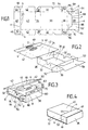
- Fig. 1 is a plan view of a carton blank for the erection of a box according to the present invention
- the blank shown in Fig. 1 has a bottom panel 30 with side flaps 32 and end flaps 34 and 36.
- the flaps 32 continue at one end in corner lugs 38, and the flap 34 continues in a top panel 40 having side flaps 42 .
- a line a is cut across the panel 40, with narrow breaks 44, and the cutting line continues in lines b across the flaps 42, leaving small uncut areas 46 at the outer line ends.
- the panel portions to the left of the cutting line are designated 48 and 50.
- the end flap 36 is provided with side lugs 52, which are narrowed by recess cuttings 54 and 56, and it continues in a panel portion 58, which is cross divided in portions 60 and 62 by means of a cutting line c.
- the outer end of the panel 58 is provided with side lugs 64.
- the cutting line c comprises outer cross line portions d continuing in portions e that converge towards the right and are interconnected, through narrow non-cut areas 66, by a cross line portion f.
- the outer line portions d leave outermost uncut areas 68.
- the box is now ready to receive its contents, e.g. pastils, which can be loaded through the open broad side.
- the foremost top panel 58 is folded inwardly over the box, and the side lugs 52 on the front flap 36 are folded rearwardly along the side flaps 32, yet still without being fastened thereto.
- the opposite top panel 40,48 is folded forwardly over the box, which it covers at full length, while the underlying upper panel 58 covers only about half the length of the box.
- a non-illustrated hot air nozzle tongue is swung into the space between the two upper panels, such that in a precisely controlled manner jets of hot air are sent against the two hatched areas A and B of the upper panel 58 as well as against the correspondingly located area portions of the underside of the top panel 40,48, these areas being shown at C and D in Fig. 2.
- the carton blank is coated with a plastic layer that is softened by such heating, whereby the two opposed area groups will be welded together by the following folding down of the top panel 40,48, upon retraction of the said nozzle tongue.
- the joining can be effected by means of glue.
- the cutting line a of the upper top panel 40,48 is located spaced from the front end 36 slightly more spaced therefrom than the cutting line portion f of the lower top panel 58.
- the side flaps 42,50 of the top panel 40,48 are folded down, whereby also the outwardly projecting side lugs 64 of the panel 58 are forced to be folded down.
- the side flaps or panels 32 may be provided with notches 72 that may cause a locking of these lugs against the panel 58 being pulled forwardly.
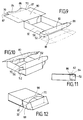
- the box is easy to open by pressing down the central portion of the top panel 40, whereby the areas 44 are broken. Thereafter, as shown in Fig. 5 by an arrow P, the upper front edge of the box is pushed forwardly, whereby is effected an initial opening of a cap lid member consisting of the flap and lug portions 36,48,50,52 and 60, this member being swung out about its lower line of connection with the body of the box, viz. the folding line between the blank portions 30 and 36, as further illustrated in Figs. 6 and 7.
- this lid member By the initial opening of this lid member both the areas 46 of cutting line b and the areas 66 of cutting line c will be broken. Thus, these non-cut areas will be of no primary importance for the guarantee sealing of the box, but the areas 66 are important because they will condition the production of boxes based on a single coherent blank (Fig. 1).
- the areas 46, which will also be broken, are important for securing that the associated free corners of the joined lugs 50 and 52 are held safely against the box sides until the box is intentionally opened; otherwise the corner could creep outwardly from the box side and thus cause unintentional damage to the packing.
- the outwardly projecting ear portions 70 on the lower top panel 62 in the closed box will be projecting into a space which is upwardly confined by the underside of the foremost portion 48 of the upper panel 40,48, while it is downwardly confined by the top edge portion of the lug 52 as folded inwardly from the front flap 36.
- the reference numeral 56 was used to designate a recess, but it may be used as well for the upper edge of the the lugs 52. These edges, by virtue of the recesses 56, will be spaced from the underside of the front flap or panel 60 such that the ear portions 70 will be received in these spaces.
- the invention provides for a highly desirable snap locking of the lid, irrespective of the lid member being of the said cap type or neck-box type.
- the cap type with its serving tray design (fig. 7) is preferable over neck-boxes, and with the invention the important result is that the cap lids are now closeable as safely as the hood lids of the neck-boxes.
- the disclosed box is highly advantageous in that it can be factory closed as a guarantee-sealed packet.
- the box will appear as a neck-box, with the free lid edges located flush with the top and side panels of the box, i.e. in a protected countersunk manner, duly supported by the neck panel 62.
- the box can be prepared as a tubular member with open sides, see Fig. 8, such that it can be folded flat from this shape or rather produced in the flat shape for compact shipment to the user's factory, where it is folded up to the tubular shape and closed at one side. Then it is filled through the other side, which is thereafter closed.
- the respective side portions should be closed in the sequence 38-32-52-42, whereby the closed box will be as shown in Fig. 4.
- Figs. 9-12 illustrate a simplified embodiment, which is usable when a guarantee closing is renounced, e.g. if the box is completed with a film envelope.
- both of the top panels are made shorter, and here the rear top panel, 80, is folded down prior to the closing of the front top panel, 82.
- These two panels are not connected mutually, but the outermost portion 84 of the panel 80 is pressed slightly offset along a cross line 86, whereby a neck effect is provided by the portion 84.
- the locking ears 70 are provided on the sides of this portion, still for cooperation with the recesses 56.
- the lid is formed simply by joining the lugs 52 with the side lugs 88 on the top panel 82, and the lid sides will be flush with the side flaps of the rear top panel 80.
Abstract
Description
- The present invention relates to cardboard packets of the hinged lid type, i.e. a box, particularly useful as a sales and pocket packing for pastils, which has at an open end a hood or cap shaped lid comprising a lid panel hinged to one mouthing wall portion of the box and skirt flaps projecting from the free edges of the lid panel over the other three mouthing wall portions. The skirt flaps comprise a front flap and two opposed side flaps, and since these lid parts are interconnected they will form a rigid caplike structure, which as a whole is hinged to one edge of the box opening.
- Boxes of this type are easy to open, e.g. with one finger, and they are well suited for pastils when the lid panel is directly hinged to an edge of the box opening, because in that case the lid panel, when swung out through 90°, will form a straight extension of the box side to which it is hinged; when the box is held such that this side is the lowermost side the opened lid will form a serving tray, into which the pastils can be shaken out from the box, and from which even the last pastil can easily be picked up. On the other hand it amounts to a serious problem that the lid is so easy to open, because it can very well open almost by itself. US-A-3 708 108 discloses a box according to the preamble of claim 1.
- Modified boxes are known, so-called neck-boxes used particularly for cigarettes, in which the lid panel is not hinged directly to the rear box side, but hinged thereto through a short extension of that rear side, whereby the hinge axis is located spaced from the rear corner of the lid panel. With this design there will be a certain resistance against the lid structure being both opened and closed, because the front skirt of the lid will be forced resiliently against the mouth edge of the box opposite to the hinge joint when the lid passes through its half-open position. This is a rather effective measure against a fully uncontrolled opening of the lid, but for pastil boxes it is inconvenient because the open lid will not just be a serving tray, but merely a serving bowl, from which it is difficult to pick up the pastils at the bottom.
- In connection with packets of the last mentioned type it has been endavoured to provide for a still better locking of the closed lid by means of laterally projecting tabs on the front mouth side of the box, such that these tabs may frictionally engage the inside of the side skirts of the lid, but this measure has not been found to particularly improve the locking effect already obtained by the said neck design itself. The projecting tabs tend to deform the side skirts of the lid or to be deformed themselves, such that the frictional engagement will not be too pronounced anyway. Examples of boxes of this type are disclosed in US-A-3,874,581 and DE-OS 25 27 540.
- On this background it is the primary purpose of the invention to provide a box of the type referred to, which is designed such that the hinged lid structure is effectively locked against unintentional opening.
- It is a further purpose to provide a box which is additionally manufactured and later closed so as to appear as a guarantee-closed neck box made out of a single blank.
- According to the invention this is achievable by the features of the characterizing portion of claim 1.
- In the following the invention is described in more detail with reference to the drawings, in which:Fig. 1 is a plan view of a carton blank for the erection of a box according to the present invention,
- Figs. 2-4 are perspective views illustrating the erection, filling and closing of the box, while
- Figs.5-7 are perspective views illustrating the opening of the box,
- Fig. 8 is a view of a modified box member, and
- Figs. 9-12 are views illustrating another modified box.
- The blank shown in Fig. 1 has a
bottom panel 30 withside flaps 32 andend flaps flaps 32 continue at one end incorner lugs 38, and theflap 34 continues in atop panel 40 havingside flaps 42 . A line a is cut across thepanel 40, withnarrow breaks 44, and the cutting line continues in lines b across theflaps 42, leaving smalluncut areas 46 at the outer line ends. The panel portions to the left of the cutting line are designated 48 and 50. - The
end flap 36 is provided withside lugs 52, which are narrowed byrecess cuttings panel portion 58, which is cross divided inportions panel 58 is provided withside lugs 64. - The cutting line c comprises outer cross line portions d continuing in portions e that converge towards the right and are interconnected, through narrow
non-cut areas 66, by a cross line portion f. The outer line portions d leave outermostuncut areas 68. - Next to these areas are formed
small side ears 70 projecting just slightly from the opposed edges of this panel, just to the right of the lines d and without any folding line at the root of the ear portions. - In Fi. 2 it is shown how the blank is erected into a condition ready for filling. The
side flaps 32 are folded up and also therear end flap 34 is folded up and preferably secured by gluing or welding to thelugs 38, while thetop panel bottom panel 30 thefront end flap 36 is folded up, still with theside lugs 52 projecting outwardly and with thetop side panel 58 folded horizontally outwardly. In this phase thefront end flap 36 is not fastened to theside flaps 32, so here theflap 36 should be supported by an outer, non-illustrated guiding rail in the box erection line. - The box is now ready to receive its contents, e.g. pastils, which can be loaded through the open broad side.
- Thereafter, see Fig. 3, the foremost
top panel 58 is folded inwardly over the box, and the side lugs 52 on thefront flap 36 are folded rearwardly along theside flaps 32, yet still without being fastened thereto. Thereafter theopposite top panel upper panel 58 covers only about half the length of the box. Just prior to the final folding down of thetop panel upper panel 58 as well as against the correspondingly located area portions of the underside of thetop panel top panel - The cutting line a of the
upper top panel front end 36 slightly more spaced therefrom than the cutting line portion f of thelower top panel 58. - Thereafter the
side flaps top panel side lugs 64 of thepanel 58 are forced to be folded down. As shown, the side flaps orpanels 32 may be provided withnotches 72 that may cause a locking of these lugs against thepanel 58 being pulled forwardly. - By the folding down of the
side flaps flap portions 42 at the rear and at the bottom are secured by gluing or welding to the outside of theinner side flaps 32 as illustrated by a hatched area E in Fig. 3, while theforemost flap portions 50 are correspondingly fastened to the outsides of the rearwardly foldedlugs 52 of thefront end flap 36, see hatched area F. Thelugs 52 are not fastened to the innerlying surfaces of theside flaps 32. - Hereafter the box will be filled and closed as shown in Fig. 4. The box will be 'guarantee closed', inasfar as it cannot be opened unless the discontinued
portions 44 of the cutting line a and theareas 46 of the cutting lines b are broken. - On the other hand the box is easy to open by pressing down the central portion of the
top panel 40, whereby theareas 44 are broken. Thereafter, as shown in Fig. 5 by an arrow P, the upper front edge of the box is pushed forwardly, whereby is effected an initial opening of a cap lid member consisting of the flap andlug portions blank portions - By the initial opening of this lid member both the
areas 46 of cutting line b and theareas 66 of cutting line c will be broken. Thus, these non-cut areas will be of no primary importance for the guarantee sealing of the box, but theareas 66 are important because they will condition the production of boxes based on a single coherent blank (Fig. 1). Theareas 46, which will also be broken, are important for securing that the associated free corners of the joinedlugs - However, by the initial or continued opening of the lid member another very important event will occur:
As best understood from viewing Figs. 3 and 6 the outwardly projectingear portions 70 on thelower top panel 62 in the closed box will be projecting into a space which is upwardly confined by the underside of theforemost portion 48 of theupper panel lug 52 as folded inwardly from thefront flap 36. Thereference numeral 56 was used to designate a recess, but it may be used as well for the upper edge of the thelugs 52. These edges, by virtue of therecesses 56, will be spaced from the underside of the front flap orpanel 60 such that theear portions 70 will be received in these spaces. Consequently, when the lid member is opened therecess edges 56 have to be pulled outwardly from their engagement with the protrudingear portions 70, whereby an opening of the lid member is resisted by a noticeable retaining action by the saidear protrusions 70. - When the lid member is reclosed the engagement between the
ear portions 70 and therecesses 56 will be reestablished such that a following opening of the lid member can hardly be effected fully unintentionally. - Thus the invention provides for a highly desirable snap locking of the lid, irrespective of the lid member being of the said cap type or neck-box type. As mentioned, for pastils the cap type with its serving tray design (fig. 7) is preferable over neck-boxes, and with the invention the important result is that the cap lids are now closeable as safely as the hood lids of the neck-boxes.
- Moreover, the disclosed box is highly advantageous in that it can be factory closed as a guarantee-sealed packet.
- It will be noted that in fact the box will appear as a neck-box, with the free lid edges located flush with the top and side panels of the box, i.e. in a protected countersunk manner, duly supported by the
neck panel 62. - The box can be prepared as a tubular member with open sides, see Fig. 8, such that it can be folded flat from this shape or rather produced in the flat shape for compact shipment to the user's factory, where it is folded up to the tubular shape and closed at one side. Then it is filled through the other side, which is thereafter closed. The respective side portions should be closed in the sequence 38-32-52-42, whereby the closed box will be as shown in Fig. 4.
- Figs. 9-12 illustrate a simplified embodiment, which is usable when a guarantee closing is renounced, e.g. if the box is completed with a film envelope. Compared with Fig. 1 both of the top panels are made shorter, and here the rear top panel, 80, is folded down prior to the closing of the front top panel, 82. These two panels are not connected mutually, but the
outermost portion 84 of thepanel 80 is pressed slightly offset along across line 86, whereby a neck effect is provided by theportion 84. The lockingears 70 are provided on the sides of this portion, still for cooperation with therecesses 56. The lid is formed simply by joining thelugs 52 with the side lugs 88 on thetop panel 82, and the lid sides will be flush with the side flaps of the reartop panel 80.
Claims (6)
- A cardboard sales and dispenser box of the hinged lid type having a hood or cap shaped lid which is hinged to a rear edge of a box mouth and has a lid panel (36) with skirt portions (48,50) covering the box panel portions (62,32) located adjacent to the box mouth at the front side and at the lateral sides of the box, said covered lateral side portions (32) of the box having respective protrusions (70) extending outwardly against the inner sides of the lateral lid skirt portions (50) that cover these side portions when the lid is closed, the lid skirt portions having exterior layers (48,50) which, in the originally closed condition of the box, are integrally connected by perforation lines (a,b) with the respective remaining exterior portions (40,42) of the front and lateral sides of the box, these having interior neck plate portions (62,32) projecting beyond the perforation lines (a,b) so as to be coverable by the skirt portions of the lid, characterized in that said inner sides of the lateral lid skirt portions (50) are provided with inwardly directed projections (56) cooperating with the said protrusions (70) of the lateral side portions (32) of the box so as to form together therewith a snap locking system for snap locking the lid in its closed position, and in that the neck plate portion (62) of the front side is constituted by a prolongation (62) of an interior layer (60) of the front skirt portion of the lid, this interior layer itself originally being a prolongation (58) of the lid panel (36) and extending so as to have its free edge located spaced from and between the said perforation line (a,b) and the bottom line of the box front panel (40), sufficiently for establishing a sealed holding engagement between its own free end portion and the inside of the exterior front panel portion (40), said interior layer (58) being provided with a transverse perforation line (c) located staggered from the exterior perforation line (a), viz. less spaced from the lid panel (36) of the closed lid, and the exterior front skirt layer (48) being sealed to the part (60) of said interior layer (58) located between the front edge of the lid panel (36) and the inner perforation line (c).
- A box according to claim 1, in which the neck plate portions (32) at the lateral sides are constituted by end portions of interior side flaps (32) of the box, these end portions being non-sealed to the lid skirt portions by which they are covered.
- A box according to claim 1, characterized in that prior to erection the front side panel member (40,48) is folded over and sealed to the prolongation (58) at either side of the pair of perforation lines (a,c), the box member thus forming a flat tube (Fig. 8) with straight outstanding side flaps (32,38,42,52) to be closed after filling of the box.
- A box according to claim 1, 2 or 3 and shaped as a so-called neck box, characterized in that the locking ears (70) are provided as edge protrusions of a front side area portion (62) extending outwardly in the box mouthing as the innermost mouthing panel in the neck mouthing, while the protruding side portions in the neck mouthing are constituted by side flaps (32) folded upwardly from the rear side panel (30) of the box.
- A box according to claim 4, characterized in that the front side area portion (62) is coherent with an interior lid panel (60) through a cutting line (c), which, having breakable interruptions (66,68), are located at the inside of the outer front side panel (48) of the lid, the lid panel (60) at its opposite end forming a hinged extension of the rear panel (30) of the box.
- A box according to claims 3 and 5, characterized in that, after filling through a broad side, the box is closed by an inward-folding of firstly the said inner front side portion (60,62) and then, from the opposite end of the box, the outer front side portion (40,48), which, by gluing or welding, is joined face to face with the inner front side portion in mutually separated areas located at respective opposite sides of the two mutually staggered cutting lines (a and c) in the respective front side portions.
Applications Claiming Priority (3)
| Application Number | Priority Date | Filing Date | Title |
|---|---|---|---|
| DK2476/89 | 1989-05-22 | ||
| DK247689A DK247689D0 (en) | 1989-05-22 | 1989-05-22 | SALE AND DELIVERY BOX FOR PASTILLES AND SIMILAR GOODS |
| PCT/DK1990/000128 WO1990014278A1 (en) | 1989-05-22 | 1990-05-22 | A sales and dispenser box for pastils and the like |
Publications (2)
| Publication Number | Publication Date |
|---|---|
| EP0473656A1 EP0473656A1 (en) | 1992-03-11 |
| EP0473656B1 true EP0473656B1 (en) | 1994-12-28 |
Family
ID=8112651
Family Applications (1)
| Application Number | Title | Priority Date | Filing Date |
|---|---|---|---|
| EP90908194A Expired - Lifetime EP0473656B1 (en) | 1989-05-22 | 1990-05-22 | A sales and dispenser box for pastils and the like |
Country Status (11)
| Country | Link |
|---|---|
| US (1) | US5203495A (en) |
| EP (1) | EP0473656B1 (en) |
| AT (1) | ATE116242T1 (en) |
| AU (1) | AU653319B2 (en) |
| DD (1) | DD301802A9 (en) |
| DE (1) | DE69015632T2 (en) |
| DK (2) | DK247689D0 (en) |
| ES (1) | ES2069076T3 (en) |
| FI (1) | FI108629B (en) |
| NO (1) | NO178617C (en) |
| WO (1) | WO1990014278A1 (en) |
Families Citing this family (18)
| Publication number | Priority date | Publication date | Assignee | Title |
|---|---|---|---|---|
| FR2677960B1 (en) * | 1991-06-20 | 1995-04-21 | Tabacs & Allumettes Ind | PACKAGE, IN RIGID CARDBOARD OR SIMILAR MATERIAL, FOR CIGARETTES. |
| DE4129609A1 (en) * | 1991-09-06 | 1993-03-11 | Focke & Co | PACKING FOR CIGARETTES OR THE LIKE |
| US5465836A (en) * | 1991-09-06 | 1995-11-14 | Focke & Co. (Gmbh & Co.) | Pack for cigarettes |
| US5307987A (en) * | 1992-12-08 | 1994-05-03 | Waldorf Corporation | Hooded carton |
| DE4410803A1 (en) * | 1994-03-30 | 1995-10-05 | Focke & Co | Hinged box for cigarettes or the like |
| DE4415572A1 (en) * | 1994-05-03 | 1995-11-09 | Focke & Co | Folded box for cigarettes etc. |
| DE4421445A1 (en) * | 1994-06-22 | 1996-01-04 | Focke & Co | Hinged box for cigarettes or the like |
| US5511722A (en) * | 1994-11-21 | 1996-04-30 | Mebane Packaging Corporation | Reclosable flip-top carton |
| IT1273845B (en) * | 1994-12-06 | 1997-07-11 | Gd Spa | RIGID PACKAGE WITH HINGED COVER FOR ELONGATED ELEMENTS, IN PARTICULAR CIGARETTES |
| US5788102A (en) * | 1996-08-19 | 1998-08-04 | Jefferson Smurfit Corporation | Flip top carton with positive side lock |
| ITMI20020560A1 (en) * | 2002-03-15 | 2003-09-15 | Gi Bi Effe Srl | BOX WITH TIPPING PANEL FOR THE EXTRACTION OF A PACKAGE LEAFLET |
| US6974033B2 (en) * | 2003-05-05 | 2005-12-13 | Smurfit-Stone Container Enterprises, Inc. | Wraparound-style shipping containers convertible to dispensing or display containers |
| ITBO20030671A1 (en) * | 2003-11-13 | 2005-05-14 | Gd Spa | METHOD AND DEVICE FOR THE REALIZATION OF A CONTAINER |
| US7600694B2 (en) * | 2004-01-27 | 2009-10-13 | Trane International Inc. | Multiple thermostats for air conditioning system with time setting feature |
| GB2428423B (en) * | 2005-07-15 | 2008-12-10 | Field Group Plc | Child-resistant packaging |
| KR20150130320A (en) | 2013-03-14 | 2015-11-23 | 크래프트 푸즈 그룹 브랜즈 엘엘씨 | Container with secure audible closure |
| USD705053S1 (en) | 2013-03-14 | 2014-05-20 | Tracy L. Nameth | Folded container |
| US11472593B1 (en) | 2019-08-29 | 2022-10-18 | Packaging Corporation Of America | Auto-locking and tamper evident container |
Family Cites Families (12)
| Publication number | Priority date | Publication date | Assignee | Title |
|---|---|---|---|---|
| CA654558A (en) * | 1962-12-25 | Di Ianni Daniel | Hinged top type container | |
| US2963214A (en) * | 1958-05-26 | 1960-12-06 | New Haven Board & Carton Compa | Cartons with replaceable end closures |
| CH380013A (en) * | 1960-03-22 | 1964-07-15 | Schmermund Alfred | Hinged lid box |
| GB948790A (en) * | 1960-11-28 | 1964-02-05 | Taylowe Ltd | Improvements in or relating to cartons |
| GB1023453A (en) * | 1961-08-04 | 1966-03-23 | Austin Packaging Ltd | Improvements in or relating to boxes or cartons |
| US3708108A (en) * | 1971-09-22 | 1973-01-02 | Burt Co Inc F | Flip top carton |
| GB1431173A (en) * | 1972-06-30 | 1976-04-07 | Molins Ltd | Boxes or packets |
| GB1512200A (en) * | 1974-06-22 | 1978-05-24 | Molins Ltd | Cigarette packets |
| GB1603108A (en) * | 1978-05-26 | 1981-11-18 | Molins Ltd | Hinged lid packets |
| DE3515775A1 (en) * | 1985-05-02 | 1986-11-06 | Focke & Co (GmbH & Co), 2810 Verden | METHOD AND DEVICE FOR PRODUCING PACKS WITH ROUNDED OR BEVELED EDGES |
| EP0204933B1 (en) * | 1985-05-02 | 1988-04-20 | Focke & Co. (GmbH & Co.) | Case with hinged lid for cigarettes or the like |
| DE3519485A1 (en) * | 1985-05-31 | 1986-12-04 | Maschinenfabrik Alfred Schmermund Gmbh & Co, 5820 Gevelsberg | PACKAGE WITH HINGED LID, CUT FOR THIS AND METHOD FOR THEIR PRODUCTION |
-
1989
- 1989-05-22 DK DK247689A patent/DK247689D0/en not_active Application Discontinuation
-
1990
- 1990-05-22 AU AU56686/90A patent/AU653319B2/en not_active Ceased
- 1990-05-22 AT AT90908194T patent/ATE116242T1/en not_active IP Right Cessation
- 1990-05-22 DD DD90340909A patent/DD301802A9/en unknown
- 1990-05-22 US US07/768,987 patent/US5203495A/en not_active Expired - Fee Related
- 1990-05-22 ES ES90908194T patent/ES2069076T3/en not_active Expired - Lifetime
- 1990-05-22 DK DK90908194.5T patent/DK0473656T3/en active
- 1990-05-22 EP EP90908194A patent/EP0473656B1/en not_active Expired - Lifetime
- 1990-05-22 DE DE69015632T patent/DE69015632T2/en not_active Expired - Fee Related
- 1990-05-22 WO PCT/DK1990/000128 patent/WO1990014278A1/en active IP Right Grant
-
1991
- 1991-11-19 NO NO914525A patent/NO178617C/en unknown
- 1991-11-22 FI FI915501A patent/FI108629B/en not_active IP Right Cessation
Also Published As
| Publication number | Publication date |
|---|---|
| DK0473656T3 (en) | 1995-06-12 |
| NO178617B (en) | 1996-01-22 |
| AU653319B2 (en) | 1994-09-29 |
| DE69015632T2 (en) | 1995-07-27 |
| NO914525D0 (en) | 1991-11-19 |
| ATE116242T1 (en) | 1995-01-15 |
| DE69015632D1 (en) | 1995-02-09 |
| WO1990014278A1 (en) | 1990-11-29 |
| NO178617C (en) | 1996-05-02 |
| DD301802A9 (en) | 1994-03-10 |
| US5203495A (en) | 1993-04-20 |
| ES2069076T3 (en) | 1995-05-01 |
| NO914525L (en) | 1991-11-19 |
| FI108629B (en) | 2002-02-28 |
| DK247689D0 (en) | 1989-05-22 |
| FI915501A0 (en) | 1991-11-22 |
| AU5668690A (en) | 1990-12-18 |
| EP0473656A1 (en) | 1992-03-11 |
Similar Documents
| Publication | Publication Date | Title |
|---|---|---|
| EP0473656B1 (en) | A sales and dispenser box for pastils and the like | |
| US10059506B2 (en) | Hinged lid packaging | |
| US5143282A (en) | Apparatus and method for maintaining closed hinged lid boxes | |
| JP4750129B2 (en) | Side open hinge lid container with audible indication of closure and / or opening | |
| US5904244A (en) | Hinge-lid box for cigarettes and blank | |
| US6105853A (en) | Exterior packaging with integrated lateral handle | |
| JP3539737B2 (en) | package | |
| EP0524720B1 (en) | Blank for a cigarette box and hinge lid cigarette carton erected from said blank | |
| EP0193365B1 (en) | Paperboard package | |
| US1414236A (en) | Collapsible box | |
| US5105971A (en) | Carton | |
| US4240576A (en) | Distribution package | |
| US5878875A (en) | Cigarette box incorporating a match drawer | |
| US7926653B2 (en) | Cigarette box and blank set for same | |
| JP4240571B2 (en) | Auto lid carton | |
| US3214009A (en) | Cigar packaging or the like | |
| US5875960A (en) | Paperboard carton for granular detergents | |
| US3266055A (en) | Reclosable containers | |
| JPH0729653B2 (en) | carton | |
| GB2139192A (en) | Flip top carton | |
| WO1979000740A1 (en) | Folding box | |
| MXPA03003127A (en) | A package. | |
| JPH07285542A (en) | Package of box | |
| US3758022A (en) | Re-closing arrangement for packages of cardboard | |
| JPS6346367Y2 (en) |
Legal Events
| Date | Code | Title | Description |
|---|---|---|---|
| PUAI | Public reference made under article 153(3) epc to a published international application that has entered the european phase |
Free format text: ORIGINAL CODE: 0009012 |
|
| 17P | Request for examination filed |
Effective date: 19911119 |
|
| AK | Designated contracting states |
Kind code of ref document: A1 Designated state(s): AT BE CH DE DK ES FR GB IT LI NL SE |
|
| 17Q | First examination report despatched |
Effective date: 19930205 |
|
| GRAA | (expected) grant |
Free format text: ORIGINAL CODE: 0009210 |
|
| REF | Corresponds to: |
Ref document number: 116242 Country of ref document: AT Date of ref document: 19950115 Kind code of ref document: T |
|
| REF | Corresponds to: |
Ref document number: 69015632 Country of ref document: DE Date of ref document: 19950209 |
|
| ITF | It: translation for a ep patent filed |
Owner name: ING. C. GREGORJ S.P.A. |
|
| ET | Fr: translation filed | ||
| REG | Reference to a national code |
Ref country code: ES Ref legal event code: FG2A Ref document number: 2069076 Country of ref document: ES Kind code of ref document: T3 |
|
| REG | Reference to a national code |
Ref country code: DK Ref legal event code: T3 |
|
| PLBE | No opposition filed within time limit |
Free format text: ORIGINAL CODE: 0009261 |
|
| STAA | Information on the status of an ep patent application or granted ep patent |
Free format text: STATUS: NO OPPOSITION FILED WITHIN TIME LIMIT |
|
| 26N | No opposition filed | ||
| PGFP | Annual fee paid to national office [announced via postgrant information from national office to epo] |
Ref country code: ES Payment date: 20000407 Year of fee payment: 11 |
|
| PGFP | Annual fee paid to national office [announced via postgrant information from national office to epo] |
Ref country code: BE Payment date: 20000515 Year of fee payment: 11 |
|
| PGFP | Annual fee paid to national office [announced via postgrant information from national office to epo] |
Ref country code: FR Payment date: 20000524 Year of fee payment: 11 |
|
| PGFP | Annual fee paid to national office [announced via postgrant information from national office to epo] |
Ref country code: AT Payment date: 20000530 Year of fee payment: 11 |
|
| PGFP | Annual fee paid to national office [announced via postgrant information from national office to epo] |
Ref country code: CH Payment date: 20000808 Year of fee payment: 11 |
|
| PG25 | Lapsed in a contracting state [announced via postgrant information from national office to epo] |
Ref country code: AT Free format text: LAPSE BECAUSE OF NON-PAYMENT OF DUE FEES Effective date: 20010522 |
|
| PG25 | Lapsed in a contracting state [announced via postgrant information from national office to epo] |
Ref country code: ES Free format text: LAPSE BECAUSE OF NON-PAYMENT OF DUE FEES Effective date: 20010523 |
|
| PG25 | Lapsed in a contracting state [announced via postgrant information from national office to epo] |
Ref country code: BE Free format text: LAPSE BECAUSE OF NON-PAYMENT OF DUE FEES Effective date: 20010531 |
|
| PG25 | Lapsed in a contracting state [announced via postgrant information from national office to epo] |
Ref country code: LI Free format text: LAPSE BECAUSE OF NON-PAYMENT OF DUE FEES Effective date: 20010621 Ref country code: CH Free format text: LAPSE BECAUSE OF NON-PAYMENT OF DUE FEES Effective date: 20010621 |
|
| BERE | Be: lapsed |
Owner name: SCHUR ENGINEERING A/S Effective date: 20010531 |
|
| REG | Reference to a national code |
Ref country code: GB Ref legal event code: IF02 |
|
| REG | Reference to a national code |
Ref country code: CH Ref legal event code: PL |
|
| PG25 | Lapsed in a contracting state [announced via postgrant information from national office to epo] |
Ref country code: FR Free format text: LAPSE BECAUSE OF NON-PAYMENT OF DUE FEES Effective date: 20020131 |
|
| REG | Reference to a national code |
Ref country code: ES Ref legal event code: FD2A Effective date: 20030303 |
|
| PGFP | Annual fee paid to national office [announced via postgrant information from national office to epo] |
Ref country code: GB Payment date: 20040504 Year of fee payment: 15 |
|
| PGFP | Annual fee paid to national office [announced via postgrant information from national office to epo] |
Ref country code: SE Payment date: 20040507 Year of fee payment: 15 |
|
| PGFP | Annual fee paid to national office [announced via postgrant information from national office to epo] |
Ref country code: NL Payment date: 20040511 Year of fee payment: 15 |
|
| PGFP | Annual fee paid to national office [announced via postgrant information from national office to epo] |
Ref country code: DE Payment date: 20040517 Year of fee payment: 15 |
|
| PGFP | Annual fee paid to national office [announced via postgrant information from national office to epo] |
Ref country code: DK Payment date: 20040528 Year of fee payment: 15 |
|
| PG25 | Lapsed in a contracting state [announced via postgrant information from national office to epo] |
Ref country code: IT Free format text: LAPSE BECAUSE OF NON-PAYMENT OF DUE FEES;WARNING: LAPSES OF ITALIAN PATENTS WITH EFFECTIVE DATE BEFORE 2007 MAY HAVE OCCURRED AT ANY TIME BEFORE 2007. THE CORRECT EFFECTIVE DATE MAY BE DIFFERENT FROM THE ONE RECORDED. Effective date: 20050522 Ref country code: GB Free format text: LAPSE BECAUSE OF NON-PAYMENT OF DUE FEES Effective date: 20050522 |
|
| PG25 | Lapsed in a contracting state [announced via postgrant information from national office to epo] |
Ref country code: SE Free format text: LAPSE BECAUSE OF NON-PAYMENT OF DUE FEES Effective date: 20050523 |
|
| PG25 | Lapsed in a contracting state [announced via postgrant information from national office to epo] |
Ref country code: DK Free format text: LAPSE BECAUSE OF NON-PAYMENT OF DUE FEES Effective date: 20050531 |
|
| PG25 | Lapsed in a contracting state [announced via postgrant information from national office to epo] |
Ref country code: NL Free format text: LAPSE BECAUSE OF NON-PAYMENT OF DUE FEES Effective date: 20051201 Ref country code: DE Free format text: LAPSE BECAUSE OF NON-PAYMENT OF DUE FEES Effective date: 20051201 |
|
| EUG | Se: european patent has lapsed | ||
| GBPC | Gb: european patent ceased through non-payment of renewal fee |
Effective date: 20050522 |
|
| NLV4 | Nl: lapsed or anulled due to non-payment of the annual fee |
Effective date: 20051201 |
|
| REG | Reference to a national code |
Ref country code: DK Ref legal event code: EBP |