EP0473452A2 - Work station having multiprocessing capability - Google Patents
Work station having multiprocessing capability Download PDFInfo
- Publication number
- EP0473452A2 EP0473452A2 EP91307973A EP91307973A EP0473452A2 EP 0473452 A2 EP0473452 A2 EP 0473452A2 EP 91307973 A EP91307973 A EP 91307973A EP 91307973 A EP91307973 A EP 91307973A EP 0473452 A2 EP0473452 A2 EP 0473452A2
- Authority
- EP
- European Patent Office
- Prior art keywords
- register
- processors
- slave
- work station
- bit positions
- Prior art date
- Legal status (The legal status is an assumption and is not a legal conclusion. Google has not performed a legal analysis and makes no representation as to the accuracy of the status listed.)
- Withdrawn
Links
Images

Classifications
-
- G—PHYSICS
- G06—COMPUTING OR CALCULATING; COUNTING
- G06F—ELECTRIC DIGITAL DATA PROCESSING
- G06F9/00—Arrangements for program control, e.g. control units
- G06F9/06—Arrangements for program control, e.g. control units using stored programs, i.e. using an internal store of processing equipment to receive or retain programs
- G06F9/46—Multiprogramming arrangements
- G06F9/52—Program synchronisation; Mutual exclusion, e.g. by means of semaphores
-
- G—PHYSICS
- G06—COMPUTING OR CALCULATING; COUNTING
- G06F—ELECTRIC DIGITAL DATA PROCESSING
- G06F9/00—Arrangements for program control, e.g. control units
- G06F9/06—Arrangements for program control, e.g. control units using stored programs, i.e. using an internal store of processing equipment to receive or retain programs
- G06F9/30—Arrangements for executing machine instructions, e.g. instruction decode
- G06F9/38—Concurrent instruction execution, e.g. pipeline or look ahead
- G06F9/3877—Concurrent instruction execution, e.g. pipeline or look ahead using a secondary processor, e.g. coprocessor
-
- G—PHYSICS
- G06—COMPUTING OR CALCULATING; COUNTING
- G06F—ELECTRIC DIGITAL DATA PROCESSING
- G06F9/00—Arrangements for program control, e.g. control units
- G06F9/06—Arrangements for program control, e.g. control units using stored programs, i.e. using an internal store of processing equipment to receive or retain programs
- G06F9/30—Arrangements for executing machine instructions, e.g. instruction decode
- G06F9/38—Concurrent instruction execution, e.g. pipeline or look ahead
- G06F9/3885—Concurrent instruction execution, e.g. pipeline or look ahead using a plurality of independent parallel functional units
- G06F9/3889—Concurrent instruction execution, e.g. pipeline or look ahead using a plurality of independent parallel functional units controlled by multiple instructions, e.g. MIMD, decoupled access or execute
Definitions
- This invention relates to a work station or similar data processing system having multiprocessing capability, and relates in particular to the synchronization of multiprocessing in a work station.
- a work station having a plurality of parallel processors for sharing jobs of a processing task to be carried out in essentially parallel manner, characterized by register means connected to said processors and having a plurality of bit positions respectively associated with said processors, each of said processors participating in said processing task being arranged to set the associated bit position of said register means to a predetermined logic state upon completion of its job, and detection means arranged to generate a completion signal upon the bit positions of said register means achieving a predetermined logic configuration.
- a work station having a main processor and a plurality of parallel slave processors includes multiprocessor synchronizing means comprising a masking register having bit positions respectively assigned to the slave processors, each bit position being arranged to be set by the main processor to a first logic state or a second logic state according to whether or not the corresponding slave processor is to participate in a processing task.
- a slave processor status register is configured in a similar manner to the mask register, the bit positions of the slave processor status register being connected to the respective slave processors, and each of these bit positions being arranged to be set to a first logic state upon job completion by the corresponding slave processor.
- Gate means generate a task completion signal to be fed both to the main processor and the slave processors upon determining coincidence between the contents of the mask register and the slave processor status register.
- the work station which incorporates the synchronizing circuit of the preferred embodiment of the invention comprises a main processor 10 which may be an Intel 80386 or 80486 microprocessor communicating through a bus 14 with a plurality of slave processors 12a...12n which may also be implemented by microprocessors such as Intel 80386 or 80486.
- Bus 14 may be a known microchannel including address/data lines 18 and various command lines 16.
- the main processor 10 assigns various jobs of a task to one or more of the slave processors 12a...12n.
- the activated slave processors will need different time periods to complete their jobs. Therefore, it is necessary that the main processor 10 monitors the time when all slave processors have completed their jobs. Previously, this was done by software monitoring which means that the main processor 10 has to interrupt its processing a large number of times for the purpose of performing interrogation cycles for ascertaining whether all slave processors have completed their jobs.
- a novel hardware feature is used in order to relieve the main processor 10 from such monitoring.
- a register block 21 including a mask register 22 and a synchronization register 24 each of which has a plurality of bit positions (flip-flops) respectively associated with or corresponding to the slave processors 12a...12n.
- bit position 1 of the register 22 and bit position 1 of the register 24 each correspond to the slave processor 12a
- bit position 2 of the register 22 and bit position 2 of the register 24 each correspond to the slave processor 12b
- bit position n of the register 22 and bit position n of the register 24 each correspond to the slave processor 12n.
- coincidence gates e.g. EXCLUSIVE-NOR gates, 30a...30n which respectively correspond to the slave processors 12a...12n.
- Corresponding bit positions of the registers 22 and 24, such as bit position 1 of the two registers 22 and 24, are connected to the inputs of a corresponding one of the EXCLUSIVE-NOR gates 30a to 30n.
- All outputs of the EXCLUSIVE-NOR gates 30a to 30n are connected to the inputs of an AND gate 32 having its output connected to a SYNC-POINT line 34 connected to inputs of all the slave processors 12a...12n and to an input of the main processor 10.
- the main processor 10 decides which of the slave processors 12a to 12n has to perform a portion of this task, such portion usually being called a job.
- the corresponding bit positions in the mask register 22 are set to a predetermined binary state, e.g. logic "1", all bit positions of the register 22 having previously been reset to logic "0" through an input R in a preceding reset cycle.
- the main processor 10 may send over a MASK line 26 a corresponding series of "0" and "1" bits to the MASK register 22.
- parallel setting of the bit positions of the MASK register 22 may be used.
- each slave processor participating in the current task sets its associated bit position in the register 24 to "1" upon completion of its job.
- the output of the corresponding one of the EXCLUSIVE-NOR gates 30a to 30n is logic "1", supplying a "1" to the AND gate 32.
- Fig. 2 there is illustrated in the upper part thereof the situation where only slave processor 1 and slave processor 2 of a total of four slave processors are involved in a processing task, the other two slave processors being masked. In the situation illustrated in the lower part of Fig. 2, all four slave processors are involved in a processing task.
- main processor 10 in operation of a work station in accordance with the invention, after the main processor has activated selected slave processors for carrying out particular jobs, the main processor 10 is free for other operations until the completion of all jobs is indicated to the main processor 10.
Landscapes
- Engineering & Computer Science (AREA)
- Software Systems (AREA)
- Theoretical Computer Science (AREA)
- Physics & Mathematics (AREA)
- General Engineering & Computer Science (AREA)
- General Physics & Mathematics (AREA)
- Multi Processors (AREA)
Abstract
A work station having multiprocessing capability comprises a main processing means (10), a plurality of slave processors (12a to 12n) for sharing jobs of a processing task to be carried out in essentially parallel manner, register means including first (24) and second (22) registers each having a plurality of bit positions respectively corresponding to said plurality of slave processors (12a to 12n), wherein each slave processor participating in said processing task sets to a first logic state the corresponding bit position of the first register (24) upon completion of its job, and wherein said main processor means (10) sets to a first logic state each bit position of said second register (22) corresponding to a slave processor which is to participate in said processing task, and coincidence detecting means for generating a completion signal upon coincidence of the states of all bit positions of said first and second registers. Said completion signal is fed to said slave processors for resetting thereof and to said main processors means for indicating thereto that all jobs have been completed.
Description
- This invention relates to a work station or similar data processing system having multiprocessing capability, and relates in particular to the synchronization of multiprocessing in a work station.
- For increasing processing speed, work stations may use several processors operating essentially in parallel on a task. Since, in general, the various processors will need different periods of time to finish their job, it is necessary to monitor completion of the jobs by all processors. Up to now this has been done by software monitoring. However, this requires a large number of monitoring cycles of the central processing unit (CPU), considerably reducing the overall processing time of the system.
- It is an object of the present invention to provide a work station using multiprocessing and having a simplified synchronization of the multiple processors.
- It is a further object of the invention to provide a work station using multiprocessing and accomplishing synchronization with a considerably reduced processing time.
- According to the invention there is provided a work station having a plurality of parallel processors for sharing jobs of a processing task to be carried out in essentially parallel manner, characterized by register means connected to said processors and having a plurality of bit positions respectively associated with said processors, each of said processors participating in said processing task being arranged to set the associated bit position of said register means to a predetermined logic state upon completion of its job, and detection means arranged to generate a completion signal upon the bit positions of said register means achieving a predetermined logic configuration.
- Preferably, a work station according to the invention having a main processor and a plurality of parallel slave processors includes multiprocessor synchronizing means comprising a masking register having bit positions respectively assigned to the slave processors, each bit position being arranged to be set by the main processor to a first logic state or a second logic state according to whether or not the corresponding slave processor is to participate in a processing task. A slave processor status register is configured in a similar manner to the mask register, the bit positions of the slave processor status register being connected to the respective slave processors, and each of these bit positions being arranged to be set to a first logic state upon job completion by the corresponding slave processor. Gate means generate a task completion signal to be fed both to the main processor and the slave processors upon determining coincidence between the contents of the mask register and the slave processor status register.
- One embodiment of the present invention will now be described by way of example with reference to the accompanying drawings, in which:-
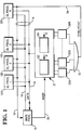
- Fig. 1 is a block diagram illustrating a synchronizing circuit and its connections to main and slave processors; and
- Fig. 2 is a schematic flow diagram illustrating the assignment of various jobs of a task to different slave processors.
- Referring to Fig. 1, the work station which incorporates the synchronizing circuit of the preferred embodiment of the invention comprises a
main processor 10 which may be an Intel 80386 or 80486 microprocessor communicating through abus 14 with a plurality of slave processors 12a...12n which may also be implemented by microprocessors such as Intel 80386 or 80486.Bus 14 may be a known microchannel including address/data lines 18 andvarious command lines 16. - For multiprocessing operations, the
main processor 10 assigns various jobs of a task to one or more of the slave processors 12a...12n. The activated slave processors will need different time periods to complete their jobs. Therefore, it is necessary that themain processor 10 monitors the time when all slave processors have completed their jobs. Previously, this was done by software monitoring which means that themain processor 10 has to interrupt its processing a large number of times for the purpose of performing interrogation cycles for ascertaining whether all slave processors have completed their jobs. - According to the invention, a novel hardware feature is used in order to relieve the
main processor 10 from such monitoring. - As illustrated in Fig. 1, there is provided a
register block 21 including amask register 22 and asynchronization register 24 each of which has a plurality of bit positions (flip-flops) respectively associated with or corresponding to the slave processors 12a...12n. For example,bit position 1 of theregister 22 andbit position 1 of theregister 24 each correspond to the slave processor 12a,bit position 2 of theregister 22 andbit position 2 of theregister 24 each correspond to the slave processor 12b... and bit position n of theregister 22 and bit position n of theregister 24 each correspond to the slave processor 12n. - Furthermore, there are provided a plurality of coincidence gates, e.g. EXCLUSIVE-NOR gates, 30a...30n which respectively correspond to the slave processors 12a...12n. Corresponding bit positions of the
registers bit position 1 of the tworegisters - All outputs of the EXCLUSIVE-NOR gates 30a to 30n are connected to the inputs of an
AND gate 32 having its output connected to a SYNC-POINT line 34 connected to inputs of all the slave processors 12a...12n and to an input of themain processor 10. - Referring now also to Fig. 2, if the
main processor 10 has to perform a processing task it decides which of the slave processors 12a to 12n has to perform a portion of this task, such portion usually being called a job. For those slave processors which are not participating in the task, i.e. which do not have a job, the corresponding bit positions in themask register 22 are set to a predetermined binary state, e.g. logic "1", all bit positions of theregister 22 having previously been reset to logic "0" through an input R in a preceding reset cycle. For the purpose of setting the bit positions of theregister 22 to selected states, themain processor 10 may send over a MASK line 26 a corresponding series of "0" and "1" bits to theMASK register 22. Alternatively, parallel setting of the bit positions of theMASK register 22 may be used. - With all the bit positions of the
register 24 having been reset to "0" through an input R in a preceding reset cycle, each slave processor participating in the current task sets its associated bit position in theregister 24 to "1" upon completion of its job. As soon as the two corresponding bits inregister 22 andregister 24 are equal, i.e. both "0" or both "1", the output of the corresponding one of the EXCLUSIVE-NOR gates 30a to 30n is logic "1", supplying a "1" to theAND gate 32. - As soon as there is coincidence in respect of all corresponding bits of the
registers AND gate 32 are "1". Upon all inputs to theAND gate 32 being "1", a SYNC-POINT signal appears at the output of theAND gate 32. The SYNC-POINT signal is applied to all the slave processors 12a to 12n and to themain processor 10, resetting all the slave processors which participated in the task to a non participating condition and indicating to themain processor 10 that all jobs have been completed. - Referring to Fig. 2 there is illustrated in the upper part thereof the situation where only
slave processor 1 andslave processor 2 of a total of four slave processors are involved in a processing task, the other two slave processors being masked. In the situation illustrated in the lower part of Fig. 2, all four slave processors are involved in a processing task. - Although in the preferred embodiment according to Fig. 1 two
registers line 34. - It will be appreciated that in operation of a work station in accordance with the invention, after the main processor has activated selected slave processors for carrying out particular jobs, the
main processor 10 is free for other operations until the completion of all jobs is indicated to themain processor 10.
Claims (6)
- A work station having a plurality of parallel processors (12a-12n) for sharing jobs of a processing task to be carried out in essentially parallel manner, characterized by register means (21) connected to said processors (12a-12n) and having a plurality of bit positions respectively associated with said processors, each of said processors participating in said processing task being arranged to set the associated bit position of said register means (21) to a predetermined logic state upon completion of its job, and detection means (30a-30n, 32) arranged to generate a completion signal upon the bit positions of said register means achieving a predetermined logic configuration.
- A work station according to claim 1, characterized in that said detection means (30a-30n, 32) is arranged to generate said completion signal upon each bit position of said register means (21) associated with a processor participating in said processing task being set to said predetermined logic state.
- A work station according to either claim 1 or claim 2, characterized by main processing means (10) and in that said parallel processors serve as slave processors (12a-12n), said completion signal being arranged to be fed to said slave processors for resetting those slave processors which participated in said processing task to a non participating condition, and also being arranged to be fed to said main processing means (10) for indicating thereto that all jobs have been completed.
- A work station according to claim 3, characterized in that said register means (21) includes a first register (24) having a plurality of bit positions respectively associated with said plurality of slave processors (12a-12n), and a second register (22) having a plurality of bit positions respectively corresponding to said plurality of slave processors, each slave processor participating in said processing task being arranged to set the associated bit position of said first register (24) to a predetermined logic state upon completion of its job, and said main processing means (10) being arranged to set to a predetermined logic state each bit position of said second register (22) corresponding to a slave processor which is to participate in said processing task, said detection means (30a-30n, 32) being arranged to generate said completion signal upon coincidence of the logic states of all bit positions of said first and second registers.
- A work station according to claim 4, including a plurality of gates (30a-30n) respectively corresponding to said plurality of slave processors (12a-12n), each gate being associated with the corresponding bit positions of said first and second registers (24,22) and being arranged to provide an output signal of predetermined logic state in response to both corresponding bit positions being in the same logic state, and a further gate (32) to which are applied the output signals of said plurality of gates (30a-30n), said further gate being arranged to provide said completion signal when all the output signals of said plurality of gates have said predetermined logic state.
- A work station according to claim 5, wherein each of said plurality of gates (30a-30n) is an EXCLUSIVE-NOR gate and said further gate (32) is an AND gate.
Applications Claiming Priority (2)
| Application Number | Priority Date | Filing Date | Title |
|---|---|---|---|
| GB909019025A GB9019025D0 (en) | 1990-08-31 | 1990-08-31 | Work station having multiprocessing capability |
| GB9019025 | 1990-08-31 |
Publications (2)
| Publication Number | Publication Date |
|---|---|
| EP0473452A2 true EP0473452A2 (en) | 1992-03-04 |
| EP0473452A3 EP0473452A3 (en) | 1993-02-03 |
Family
ID=10681447
Family Applications (1)
| Application Number | Title | Priority Date | Filing Date |
|---|---|---|---|
| EP19910307973 Withdrawn EP0473452A3 (en) | 1990-08-31 | 1991-08-30 | Work station having multiprocessing capability |
Country Status (3)
| Country | Link |
|---|---|
| EP (1) | EP0473452A3 (en) |
| JP (1) | JPH04350758A (en) |
| GB (1) | GB9019025D0 (en) |
Cited By (26)
| Publication number | Priority date | Publication date | Assignee | Title |
|---|---|---|---|---|
| EP0602906A1 (en) * | 1992-12-18 | 1994-06-22 | Fujitsu Limited | Synchronous processing method and apparatus for a plurality of processors executing a plurality of programs in parallel |
| WO1996037834A1 (en) * | 1995-05-25 | 1996-11-28 | Cray Research, Inc. | Barrier and eureka synchronization architecture for multiprocessors |
| WO1997034226A1 (en) * | 1996-03-11 | 1997-09-18 | Mitel Corporation | Scaleable double parallel digital signal processor |
| US5864738A (en) * | 1996-03-13 | 1999-01-26 | Cray Research, Inc. | Massively parallel processing system using two data paths: one connecting router circuit to the interconnect network and the other connecting router circuit to I/O controller |
| US5970232A (en) * | 1997-11-17 | 1999-10-19 | Cray Research, Inc. | Router table lookup mechanism |
| US6055618A (en) * | 1995-10-31 | 2000-04-25 | Cray Research, Inc. | Virtual maintenance network in multiprocessing system having a non-flow controlled virtual maintenance channel |
| US6101181A (en) * | 1997-11-17 | 2000-08-08 | Cray Research Inc. | Virtual channel assignment in large torus systems |
| US6216174B1 (en) | 1998-09-29 | 2001-04-10 | Silicon Graphics, Inc. | System and method for fast barrier synchronization |
| US6230252B1 (en) | 1997-11-17 | 2001-05-08 | Silicon Graphics, Inc. | Hybrid hypercube/torus architecture |
| US6674720B1 (en) | 1999-09-29 | 2004-01-06 | Silicon Graphics, Inc. | Age-based network arbitration system and method |
| US7334110B1 (en) | 2003-08-18 | 2008-02-19 | Cray Inc. | Decoupled scalar/vector computer architecture system and method |
| US7366873B1 (en) | 2003-08-18 | 2008-04-29 | Cray, Inc. | Indirectly addressed vector load-operate-store method and apparatus |
| US7379424B1 (en) | 2003-08-18 | 2008-05-27 | Cray Inc. | Systems and methods for routing packets in multiprocessor computer systems |
| US7421565B1 (en) | 2003-08-18 | 2008-09-02 | Cray Inc. | Method and apparatus for indirectly addressed vector load-add -store across multi-processors |
| US7437521B1 (en) | 2003-08-18 | 2008-10-14 | Cray Inc. | Multistream processing memory-and barrier-synchronization method and apparatus |
| US7503048B1 (en) | 2003-08-18 | 2009-03-10 | Cray Incorporated | Scheduling synchronization of programs running as streams on multiple processors |
| US7519771B1 (en) | 2003-08-18 | 2009-04-14 | Cray Inc. | System and method for processing memory instructions using a forced order queue |
| US7543133B1 (en) | 2003-08-18 | 2009-06-02 | Cray Inc. | Latency tolerant distributed shared memory multiprocessor computer |
| US7577816B2 (en) | 2003-08-18 | 2009-08-18 | Cray Inc. | Remote translation mechanism for a multinode system |
| US7669036B2 (en) * | 2007-06-14 | 2010-02-23 | Qualcomm Incorporated | Direct path monitoring by primary processor to each status register in pipeline chained secondary processors for task allocation via downstream communication |
| US7735088B1 (en) | 2003-08-18 | 2010-06-08 | Cray Inc. | Scheduling synchronization of programs running as streams on multiple processors |
| US7743223B2 (en) | 2003-08-18 | 2010-06-22 | Cray Inc. | Decoupling of write address from its associated write data in a store to a shared memory in a multiprocessor system |
| US7757497B1 (en) | 2005-03-09 | 2010-07-20 | Cray Inc. | Method and apparatus for cooling electronic components |
| US8307194B1 (en) | 2003-08-18 | 2012-11-06 | Cray Inc. | Relaxed memory consistency model |
| US20230067432A1 (en) * | 2020-04-29 | 2023-03-02 | Stream Computing Inc. | Task allocation method, apparatus, electronic device, and computer-readable storage medium |
| US12511158B2 (en) * | 2020-03-13 | 2025-12-30 | Stream Computing Inc. | Task allocation method, apparatus, electronic device and computer-readable storage medium |
-
1990
- 1990-08-31 GB GB909019025A patent/GB9019025D0/en active Pending
-
1991
- 1991-08-29 JP JP24243191A patent/JPH04350758A/en active Pending
- 1991-08-30 EP EP19910307973 patent/EP0473452A3/en not_active Withdrawn
Non-Patent Citations (1)
| Title |
|---|
| IBM TECHNICAL DISCLOSURE BULLETIN. vol. 31, no. 11, April 1989, NEW YORK US pages 382 - 389 'Low-cost device for contention-free barrier synchronization' * |
Cited By (29)
| Publication number | Priority date | Publication date | Assignee | Title |
|---|---|---|---|---|
| EP0602906A1 (en) * | 1992-12-18 | 1994-06-22 | Fujitsu Limited | Synchronous processing method and apparatus for a plurality of processors executing a plurality of programs in parallel |
| WO1996037834A1 (en) * | 1995-05-25 | 1996-11-28 | Cray Research, Inc. | Barrier and eureka synchronization architecture for multiprocessors |
| US5721921A (en) * | 1995-05-25 | 1998-02-24 | Cray Research, Inc. | Barrier and eureka synchronization architecture for multiprocessors |
| US6055618A (en) * | 1995-10-31 | 2000-04-25 | Cray Research, Inc. | Virtual maintenance network in multiprocessing system having a non-flow controlled virtual maintenance channel |
| WO1997034226A1 (en) * | 1996-03-11 | 1997-09-18 | Mitel Corporation | Scaleable double parallel digital signal processor |
| US5960209A (en) * | 1996-03-11 | 1999-09-28 | Mitel Corporation | Scaleable digital signal processor with parallel architecture |
| US5864738A (en) * | 1996-03-13 | 1999-01-26 | Cray Research, Inc. | Massively parallel processing system using two data paths: one connecting router circuit to the interconnect network and the other connecting router circuit to I/O controller |
| US5970232A (en) * | 1997-11-17 | 1999-10-19 | Cray Research, Inc. | Router table lookup mechanism |
| US6101181A (en) * | 1997-11-17 | 2000-08-08 | Cray Research Inc. | Virtual channel assignment in large torus systems |
| US6230252B1 (en) | 1997-11-17 | 2001-05-08 | Silicon Graphics, Inc. | Hybrid hypercube/torus architecture |
| US6216174B1 (en) | 1998-09-29 | 2001-04-10 | Silicon Graphics, Inc. | System and method for fast barrier synchronization |
| US6674720B1 (en) | 1999-09-29 | 2004-01-06 | Silicon Graphics, Inc. | Age-based network arbitration system and method |
| US7379424B1 (en) | 2003-08-18 | 2008-05-27 | Cray Inc. | Systems and methods for routing packets in multiprocessor computer systems |
| US7793073B2 (en) | 2003-08-18 | 2010-09-07 | Cray Inc. | Method and apparatus for indirectly addressed vector load-add-store across multi-processors |
| US7334110B1 (en) | 2003-08-18 | 2008-02-19 | Cray Inc. | Decoupled scalar/vector computer architecture system and method |
| US7421565B1 (en) | 2003-08-18 | 2008-09-02 | Cray Inc. | Method and apparatus for indirectly addressed vector load-add -store across multi-processors |
| US7437521B1 (en) | 2003-08-18 | 2008-10-14 | Cray Inc. | Multistream processing memory-and barrier-synchronization method and apparatus |
| US7503048B1 (en) | 2003-08-18 | 2009-03-10 | Cray Incorporated | Scheduling synchronization of programs running as streams on multiple processors |
| US7519771B1 (en) | 2003-08-18 | 2009-04-14 | Cray Inc. | System and method for processing memory instructions using a forced order queue |
| US7543133B1 (en) | 2003-08-18 | 2009-06-02 | Cray Inc. | Latency tolerant distributed shared memory multiprocessor computer |
| US7577816B2 (en) | 2003-08-18 | 2009-08-18 | Cray Inc. | Remote translation mechanism for a multinode system |
| US8307194B1 (en) | 2003-08-18 | 2012-11-06 | Cray Inc. | Relaxed memory consistency model |
| US7735088B1 (en) | 2003-08-18 | 2010-06-08 | Cray Inc. | Scheduling synchronization of programs running as streams on multiple processors |
| US7743223B2 (en) | 2003-08-18 | 2010-06-22 | Cray Inc. | Decoupling of write address from its associated write data in a store to a shared memory in a multiprocessor system |
| US7366873B1 (en) | 2003-08-18 | 2008-04-29 | Cray, Inc. | Indirectly addressed vector load-operate-store method and apparatus |
| US7757497B1 (en) | 2005-03-09 | 2010-07-20 | Cray Inc. | Method and apparatus for cooling electronic components |
| US7669036B2 (en) * | 2007-06-14 | 2010-02-23 | Qualcomm Incorporated | Direct path monitoring by primary processor to each status register in pipeline chained secondary processors for task allocation via downstream communication |
| US12511158B2 (en) * | 2020-03-13 | 2025-12-30 | Stream Computing Inc. | Task allocation method, apparatus, electronic device and computer-readable storage medium |
| US20230067432A1 (en) * | 2020-04-29 | 2023-03-02 | Stream Computing Inc. | Task allocation method, apparatus, electronic device, and computer-readable storage medium |
Also Published As
| Publication number | Publication date |
|---|---|
| JPH04350758A (en) | 1992-12-04 |
| EP0473452A3 (en) | 1993-02-03 |
| GB9019025D0 (en) | 1990-10-17 |
Similar Documents
| Publication | Publication Date | Title |
|---|---|---|
| EP0473452A2 (en) | Work station having multiprocessing capability | |
| EP0330836A3 (en) | Method for multiprocessor system having self-allocating processors | |
| GB2114333A (en) | Shared facility allocation system | |
| FI813223L (en) | MULTIPROSESSORSYSTEM | |
| US3895353A (en) | Data processing systems | |
| EP0147599A2 (en) | Data processing system including a main processor and a co-processor and co-processor error handling logic | |
| US5107420A (en) | Synchronous apparatus for processors | |
| US6789258B1 (en) | System and method for performing a synchronization operation for multiple devices in a computer system | |
| US4894826A (en) | Message generating communication apparatus having a message preamble format allowing parts of certain messages to be ignored | |
| JPS63155336A (en) | data processing equipment | |
| EP0827070B1 (en) | Pipelined computer | |
| KR100321274B1 (en) | Pipeline-type multi-processor system | |
| KR940011041B1 (en) | Microcomputer | |
| GB2139384A (en) | Computing apparatus | |
| JPH02105961A (en) | Multiprocessor synchronization system | |
| JP2783192B2 (en) | Barrier synchronizer | |
| KR940002711A (en) | Interrupt handler and its method | |
| JPH02230356A (en) | Bus extension device for information processor | |
| JPH07120343B2 (en) | Multiprocessor system | |
| SU1564625A1 (en) | Duplex computing system with check | |
| KR100282811B1 (en) | Systems and Methods for Interprocessor Bus Arbitration Error Prevention in Exchanges | |
| JPS62285147A (en) | Tracer control method | |
| RU2101759C1 (en) | Computing unit with alternating processing of several instruction flows | |
| JPS5866136A (en) | Interruption detection | |
| JPS58105370A (en) | Data processing system |
Legal Events
| Date | Code | Title | Description |
|---|---|---|---|
| PUAI | Public reference made under article 153(3) epc to a published international application that has entered the european phase |
Free format text: ORIGINAL CODE: 0009012 |
|
| AK | Designated contracting states |
Kind code of ref document: A2 Designated state(s): DE GB |
|
| PUAL | Search report despatched |
Free format text: ORIGINAL CODE: 0009013 |
|
| AK | Designated contracting states |
Kind code of ref document: A3 Designated state(s): DE GB |
|
| STAA | Information on the status of an ep patent application or granted ep patent |
Free format text: STATUS: THE APPLICATION IS DEEMED TO BE WITHDRAWN |
|
| 18D | Application deemed to be withdrawn |
Effective date: 19930804 |