EP0471849A1 - Method of generating dot signal corresponding to character pattern and device therefor - Google Patents
Method of generating dot signal corresponding to character pattern and device therefor Download PDFInfo
- Publication number
- EP0471849A1 EP0471849A1 EP91904796A EP91904796A EP0471849A1 EP 0471849 A1 EP0471849 A1 EP 0471849A1 EP 91904796 A EP91904796 A EP 91904796A EP 91904796 A EP91904796 A EP 91904796A EP 0471849 A1 EP0471849 A1 EP 0471849A1
- Authority
- EP
- European Patent Office
- Prior art keywords
- straight lines
- points
- end point
- character pattern
- noticeable
- Prior art date
- Legal status (The legal status is an assumption and is not a legal conclusion. Google has not performed a legal analysis and makes no representation as to the accuracy of the status listed.)
- Granted
Links
Images


Classifications
-
- G—PHYSICS
- G06—COMPUTING; CALCULATING OR COUNTING
- G06T—IMAGE DATA PROCESSING OR GENERATION, IN GENERAL
- G06T11/00—2D [Two Dimensional] image generation
- G06T11/20—Drawing from basic elements, e.g. lines or circles
- G06T11/203—Drawing of straight lines or curves
-
- G—PHYSICS
- G09—EDUCATION; CRYPTOGRAPHY; DISPLAY; ADVERTISING; SEALS
- G09G—ARRANGEMENTS OR CIRCUITS FOR CONTROL OF INDICATING DEVICES USING STATIC MEANS TO PRESENT VARIABLE INFORMATION
- G09G1/00—Control arrangements or circuits, of interest only in connection with cathode-ray tube indicators; General aspects or details, e.g. selection emphasis on particular characters, dashed line or dotted line generation; Preprocessing of data
- G09G1/06—Control arrangements or circuits, of interest only in connection with cathode-ray tube indicators; General aspects or details, e.g. selection emphasis on particular characters, dashed line or dotted line generation; Preprocessing of data using single beam tubes, e.g. three-dimensional or perspective representation, rotation or translation of display pattern, hidden lines, shadows
- G09G1/14—Control arrangements or circuits, of interest only in connection with cathode-ray tube indicators; General aspects or details, e.g. selection emphasis on particular characters, dashed line or dotted line generation; Preprocessing of data using single beam tubes, e.g. three-dimensional or perspective representation, rotation or translation of display pattern, hidden lines, shadows the beam tracing a pattern independent of the information to be displayed, this latter determining the parts of the pattern rendered respectively visible and invisible
-
- Y—GENERAL TAGGING OF NEW TECHNOLOGICAL DEVELOPMENTS; GENERAL TAGGING OF CROSS-SECTIONAL TECHNOLOGIES SPANNING OVER SEVERAL SECTIONS OF THE IPC; TECHNICAL SUBJECTS COVERED BY FORMER USPC CROSS-REFERENCE ART COLLECTIONS [XRACs] AND DIGESTS
- Y10—TECHNICAL SUBJECTS COVERED BY FORMER USPC
- Y10S—TECHNICAL SUBJECTS COVERED BY FORMER USPC CROSS-REFERENCE ART COLLECTIONS [XRACs] AND DIGESTS
- Y10S345/00—Computer graphics processing and selective visual display systems
- Y10S345/947—Font character edge processing
Definitions
- the present invention relates to a method and a system for generating dot patterns on the basis of so-called outline font data for determining character pattern outlines.
- a so-called outline font method such that the outline of a character pattern is divided into a plurality of areas j0, j1, j2, ... as shown in Fig. 1, for instance; the start and end point coordinates of these areas j0, j1, j2 ... are previously stored as data; and the divided outlines are interpolated on the basis of dot signals before outputted.
- dot signals corresponding to a character pattern are generated through complicated processing such as conversion into outline information described by only straight lines, conversion into outline data composed of dot signals on dot coordinates, etc. Therefore, there exists a problem in that a great amount of memory capacity is required, because the outline information composed of dot signals must be temporarily stored in some memory medium in the process of forming the outline information composed of dot signals on the basis of outline data described by an approximate function and the process of forming dot signals corresponding to the character pattern on the basis of the outline information composed of dot signals.
- the object of the present invention is to reduce the memory capacity required to store the outline information composed of dot signals by directly forming dot signals corresponding to the character pattern on the basis of outline information described by only straight lines.
- one end point of the outline information described by only straight lines is noticed; two straight lines composed of dot signals are extended toward two end points adjacent to the afore-mentioned noticeable end point.
- a pair of points are generated sequentially at the extreme points of the two straight lines to extend these straight lines, respectively.
- a straight line composed of dot signals is generated between a pair of the points.
- the above-mentioned processing is repeated until the straight line extending between a pair of the points reaches the two adjacent end points.
- dot signals corresponding to a character pattern can be formed directly on the basis of the outline information described by only straight lines. Therefore, since it is unnecessary to temporarily store the outline information composed of dot signals, the memory capacity can be reduced markedly.
- Fig. 3 shows a processing of extending a straight line from an end point p0 toward an end point p1 on dot coordinates.
- This method is an interpolation method known as DDA (Digital Differential Analyser).
- dot signals corresponding to a character pattern can be generated by utilizing the DDA method as follows:
- Two straight lines are simultaneously extended from this noticeable end point p0 toward two end points p1 and p2, respectively by simultaneously executing the ADD method between the noticeable end point p0 on the outline information described by only straight lines and two end points p1 and p2 adjacent to this noticeable end point p0.
- dot signals within a triangular area determined by three end points p0, p1 and p2 can be obtained.
- the character pattern is being formed on the basis of the outline information in the above process
- a problem may arise when the outline information is recessed in the form as shown in Fig. 6.
- the newly formed dot signals and already formed character pattern are NANDed in the dot signal generating process. That is, the dot signals within the area D which are erroneously generated by the processing on the basis of the noticeable end point p0 in Fig. 6 and the dot signals generated by the succeeding processing on the basis of the noticeable end point p3 are NANDed to cancel the dot signals within the area D.
- An outline information storing section 1 previously stores the outline information described by only straight lines or by approximated curves determined by the Conic-spline function or Bezier function, etc.
- a data separating section 2 separates signals transmitted from a host apparatus (not shown) into a character code signal and an attribute signal representative of a character size, respectively.
- the character code signal is outputted to a reading section 3, and the attribute signal is outputted to a coordinate calculating section 4.
- the reading reaction 3 reads the outline information of characters corresponding to the received character code signal from the storing section 1, and transmits the read outline information to the coordinate calculating section 4.
- the outline information read from the storing section 1 is referred to as the original outline information, hereinafter.
- the coordinate calculating section 4 converts the size of the original outline information read from the storing section 1 into a character size designated by the host apparatus on the coordinates, and transmits the converted size to an outline converting section 5.
- the outline converting section 5 reproduces Conic-spline curves or Bezier curves on the basis of start point coordinates, end point coordinates, and control point coordinates included in the original outline information when the inputted original outline information is described by approximation curves based upon the Conic-spline function or Bezier function; approximates these curves by straight lines, and outputs character outline information described by only straight lines to an end point deciding section 6.
- the end point deciding section 6 decides end points of the respective straight lines constituting outlines on the basis of the outline information described by only straight lines, and transmits coordinate information at the respective end point to a DDA calculating section 7 and a complete discriminating section 11.
- the DDA calculating section 7 notices one of end points inputted thereto, extends two straight lines from the noticeable end point toward two adjacent end points, and forms a pair of interpolated points at the extreme ends of the two straight lines, respectively in accordance with the DDA method, as already explained with reference to Figs. 3 and 4.
- the coordinate information of a pair of the formed interpolated points are given to a straight line generating section 8 and the complete discriminating section 11.
- the straight line generating section 8 forms a straight line composed of dot signals between a pair of interpolated points inputted in accordance with the DDA method, as already described with reference to Fig. 4.
- the dot signals of this formed straight line are inputted to a NAND gate 9, and NANDed together with the already formed dot signals read from a buffer 10 at the corresponding coordinates.
- the ANDed results of these dot signals are written in the buffer 10. Further, since the buffer 10 is originally blanked, although a straight line formed by the straight line generating section 8 is written as it is in the buffer 10, when a straight line is generated erroneously at the recessed portion, this straight line is blanked through the NAND processing as already described with reference to Fig. 6. Whenever a straight line has been generated between a pair of interpolated points, the straight line generating section 8 transmits straight line complete information to the complete discriminating section 11.
- the complete discriminating section 11 discriminates whether the straight line formed by the DDA calculating section 7 reaches either one of end points adjacent to the noticeable end point on the basis of the coordinate information at the interpolated points inputted from the DDA calculating section 7, and transmits end point change information to the DDA calculating section 7 when having recognized its arrival to one end point.
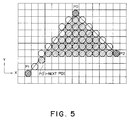
- the DDA calculating section 7 changes a noticeable end point and extends two straight lines from a newly noticed end point toward the adjacent end points as already described with reference to Fig. 5.
- the complete discriminating section 11 further discriminates whether the formation of all the straight lines constituting character outlines have been completed by the DDA calculating section 7, and transmits a complete signal to a buffer data output section 12, at the timing when the completion has been recognized and the final straight line between two interpolated points (generated at the completion time point) has been formed by the straight line generating section 8.
- the buffer data output section 12 reads the dot pattern from the buffer 10 and transmits it to a printing mechanism not shown.
- each of all the necessary characters is divided into a plurality of areas suitable for approximating the outlines of each character pattern into straight lines, the Conic-spline function or Bezier function, and further the respective start, end and control points are determined for each area.
- the original outline information of each character thus obtained is previously stored in the outline data storing section 1 with character codes as addresses.
- a character signal is inputted from a host apparatus (not shown) (in step 20)
- the character signal is separated into the character code signal and the attribute signal by the data separating section 2.
- the separated character code signal has access to the outline data storing section 1 via the reading section 3, and the separated attribute signal is inputted to the coordinate calculating section 4 to set the character size (in step 21).
- the reading section 3 reads the original outline information corresponding to each character for each area where the outline is formed (in step 22).
- the coordinate calculating section 4 converts the coordinates of start, end and control points which constitute the original outline information read from the reading section 3 into coordinates corresponding to the magnitude of the character size designated by the attribute signal (in step 23), and outputs the converted coordinates to the outline converting section 5.
- the outline converting section 5 calculates the Conic-spline function or Bezier function corresponding to the inputted coordinates, approximates and divides the functions into straight lines, and outputs the straight lines to the end point deciding section 6 (in step 24). As described above, after the outline information by which the whole of one character is described by only straight lines has been formed (in step 25), the end point deciding section 6 and other sections 7 and after convert the outline information into dot pattern signals (in step 26).
- the end point deciding section 6 decides end points of the respective straight lines which constitute the character outlines, and the DDA calculating section 7 takes any given end point p0 and a pair of two end points p1 and p2 adjacent to the end point p0 (in step 30) and extends two straight lines from the noticeable end point p0 toward the two end points p1 and p2 (in step 32).
- the straight line generating section 8 generates a straight line composed of dots between two interpolated points p1n and p2n at the extreme ends of the two extension lines and further executes NAND calculation of these straight lines (in step 32).
- the discriminating section 11 discriminates whether the extreme ends p1n and p2n of the extension lines reach the end points p1 and p2. If either of the extreme ends p1n and p2n of the straight lines reaches the end point p1 or p2 (in step 33 or 35), an extreme end point of a straight line which does not reach the end point is determined as the subsequent noticeable end point p0 (in step 34 or 36).
Abstract
Description
- The present invention relates to a method and a system for generating dot patterns on the basis of so-called outline font data for determining character pattern outlines.
- With advance of higher reliability of print output in word processors, for instance, the number of dots which constitute a character pattern has been increased rapidly. Therefore, there arises a problem in that the capacity of a character generator memory for storing characters as dot pattern data increases more and more.
- To overcome the problem as described above, a so-called outline font method has been proposed such that the outline of a character pattern is divided into a plurality of areas j0, j1, j2, ... as shown in Fig. 1, for instance; the start and end point coordinates of these areas j0, j1, j2 ... are previously stored as data; and the divided outlines are interpolated on the basis of dot signals before outputted.
- In this method, since not only high reliable characters of many dots can be outputted in spite of a relatively small amount of data to be stored, but also the character sizes can be expanded and contracted by coordinate calculation, there exists an advantage of coping with characters of various sizes.
- However, since the outline information as described above can be obtained by approximating a curve J for forming a character outline as shown in Fig. 2A on the basis of straight lines K, K and a circular arc L as shown in Fig. 2B, when the curve is required to be approximated precisely in particular, there exists a problem in that a great number of circular arcs of different radii must be stored so that the memory capacity inevitably increases.
- To overcome the above-mentioned problem, there has been proposed another method of approximating the character outline by use of Conic-spline or Bezier function which can determine a curve on the basis of three points of start and end points A and B of a curve representing an outline and a control point C indicative of an intersection of two tangent lines described at these points A and B as shown in Fig. 2C. When the Conic-spline or Bezier function is adopted, it is possible to approximate the character outline by a smooth curve in spite of a relatively small memory capacity.
- In the prior-art character pattern signal generating systems, however, dot signals corresponding to a character pattern are generated through complicated processing such as conversion into outline information described by only straight lines, conversion into outline data composed of dot signals on dot coordinates, etc. Therefore, there exists a problem in that a great amount of memory capacity is required, because the outline information composed of dot signals must be temporarily stored in some memory medium in the process of forming the outline information composed of dot signals on the basis of outline data described by an approximate function and the process of forming dot signals corresponding to the character pattern on the basis of the outline information composed of dot signals.
- The object of the present invention is to reduce the memory capacity required to store the outline information composed of dot signals by directly forming dot signals corresponding to the character pattern on the basis of outline information described by only straight lines.
- In the method according to the present invention, one end point of the outline information described by only straight lines is noticed; two straight lines composed of dot signals are extended toward two end points adjacent to the afore-mentioned noticeable end point. In this extension process, a pair of points are generated sequentially at the extreme points of the two straight lines to extend these straight lines, respectively. Whenever a pair of the points are generated, a straight line composed of dot signals is generated between a pair of the points. The above-mentioned processing is repeated until the straight line extending between a pair of the points reaches the two adjacent end points. As described above, dot signals corresponding to a character pattern can be formed directly on the basis of the outline information described by only straight lines. Therefore, since it is unnecessary to temporarily store the outline information composed of dot signals, the memory capacity can be reduced markedly.
-
- Figs. 1, 2A, 2B and 2C are illustrations for assistance in explaining prior-art method of forming character outline information;
- Figs. 3, 4, 5 and 6 are illustrations for assistance in explaining the dot signal generating method according to the present invention;
- Fig. 7 is a block diagram showing an embodiment of the dot signal generating system according to the present invention; and
- Figs. 8 and 9 are flowcharts for assistance in explaining the operation of the embodiment shown in Fig. 7.
- With reference to Figs. 3 to 6, an embodiment of the character pattern generating method according to the present invention will be described hereinbelow.
- Fig. 3 shows a processing of extending a straight line from an end point p0 toward an end point p1 on dot coordinates. Assuming that the straight line has been extended to a point pn (coordinates: pxn, pyn), a point p(n+l) (coordinates: p(n+l)x, p(n+l)y) to be generated next can be obtained by the following formulae:
When the horizontal and vertical distance components between the two end points p0 and p1 are denoted as Δx, Δy, respectively, if 0 ≦ Δx ≦ Δy,


- This method is an interpolation method known as DDA (Digital Differential Analyser).
- In the present invention, dot signals corresponding to a character pattern can be generated by utilizing the DDA method as follows:
- In Fig. 4, any given end point p0 on the outline information described by only straight lines is noticed.
- Two straight lines are simultaneously extended from this noticeable end point p0 toward two end points p1 and p2, respectively by simultaneously executing the ADD method between the noticeable end point p0 on the outline information described by only straight lines and two end points p1 and p2 adjacent to this noticeable end point p0.
- The assumption is made that a pair of points p1n and p2n interpolated at the n-th time beginning from the end point p0, for instance during the execution of this DDA method are obtained simultaneously. At this time, a point string q1, q2, q3, q4, ... which constitute a straight line between the two interpolated points p1n and p2n can be obtained by executing the DDA method between a pair of the interpolated points. This point string represents dot signals corresponding to a character pattern.
- By repeating the above processes B and C, dot signals within a triangular area determined by three end points p0, p1 and p2 can be obtained.
- As shown in Fig. 5, when the execution reaches either one of the end points p1 and p2 in the above process B, a subsequent point p0' generated on the side where the execution does not yet reach the end is determined as the subsequent noticeable end point p0 on the outline information described by only straight lines.
- By repeating the above processes A, B, C and D, all the outline information described by only straight lines can be converted into dot signals corresponding to a character pattern.
- Further, when the character pattern is being formed on the basis of the outline information in the above process, a problem may arise when the outline information is recessed in the form as shown in Fig. 6. In other words, there exists a possibility that dot signals are erroneously generated in an area D outside the recessed outline. To overcome this problem, the newly formed dot signals and already formed character pattern are NANDed in the dot signal generating process. That is, the dot signals within the area D which are erroneously generated by the processing on the basis of the noticeable end point p0 in Fig. 6 and the dot signals generated by the succeeding processing on the basis of the noticeable end point p3 are NANDed to cancel the dot signals within the area D.
- An embodiment of the system for embodying the method according to the present invention is shown in Fig. 7. An outline
information storing section 1 previously stores the outline information described by only straight lines or by approximated curves determined by the Conic-spline function or Bezier function, etc. - A
data separating section 2 separates signals transmitted from a host apparatus (not shown) into a character code signal and an attribute signal representative of a character size, respectively. The character code signal is outputted to areading section 3, and the attribute signal is outputted to acoordinate calculating section 4. - The
reading reaction 3 reads the outline information of characters corresponding to the received character code signal from thestoring section 1, and transmits the read outline information to thecoordinate calculating section 4. The outline information read from the storingsection 1 is referred to as the original outline information, hereinafter. - The
coordinate calculating section 4 converts the size of the original outline information read from the storingsection 1 into a character size designated by the host apparatus on the coordinates, and transmits the converted size to anoutline converting section 5. - The
outline converting section 5 reproduces Conic-spline curves or Bezier curves on the basis of start point coordinates, end point coordinates, and control point coordinates included in the original outline information when the inputted original outline information is described by approximation curves based upon the Conic-spline function or Bezier function; approximates these curves by straight lines, and outputs character outline information described by only straight lines to an endpoint deciding section 6. - The end
point deciding section 6 decides end points of the respective straight lines constituting outlines on the basis of the outline information described by only straight lines, and transmits coordinate information at the respective end point to aDDA calculating section 7 and a complete discriminating section 11. - The
DDA calculating section 7 notices one of end points inputted thereto, extends two straight lines from the noticeable end point toward two adjacent end points, and forms a pair of interpolated points at the extreme ends of the two straight lines, respectively in accordance with the DDA method, as already explained with reference to Figs. 3 and 4. The coordinate information of a pair of the formed interpolated points are given to a straightline generating section 8 and the complete discriminating section 11. - The straight
line generating section 8 forms a straight line composed of dot signals between a pair of interpolated points inputted in accordance with the DDA method, as already described with reference to Fig. 4. The dot signals of this formed straight line are inputted to aNAND gate 9, and NANDed together with the already formed dot signals read from abuffer 10 at the corresponding coordinates. The ANDed results of these dot signals are written in thebuffer 10. Further, since thebuffer 10 is originally blanked, although a straight line formed by the straightline generating section 8 is written as it is in thebuffer 10, when a straight line is generated erroneously at the recessed portion, this straight line is blanked through the NAND processing as already described with reference to Fig. 6. Whenever a straight line has been generated between a pair of interpolated points, the straightline generating section 8 transmits straight line complete information to the complete discriminating section 11. - The complete discriminating section 11 discriminates whether the straight line formed by the
DDA calculating section 7 reaches either one of end points adjacent to the noticeable end point on the basis of the coordinate information at the interpolated points inputted from theDDA calculating section 7, and transmits end point change information to theDDA calculating section 7 when having recognized its arrival to one end point. In response to the end point change information, theDDA calculating section 7 changes a noticeable end point and extends two straight lines from a newly noticed end point toward the adjacent end points as already described with reference to Fig. 5. The complete discriminating section 11 further discriminates whether the formation of all the straight lines constituting character outlines have been completed by theDDA calculating section 7, and transmits a complete signal to a bufferdata output section 12, at the timing when the completion has been recognized and the final straight line between two interpolated points (generated at the completion time point) has been formed by the straightline generating section 8. - In response to the complete signal, the buffer
data output section 12 reads the dot pattern from thebuffer 10 and transmits it to a printing mechanism not shown. - The operation of the system thus constructed will be described with reference to a flowchart shown in Fig. 8. As the preparation stage, each of all the necessary characters is divided into a plurality of areas suitable for approximating the outlines of each character pattern into straight lines, the Conic-spline function or Bezier function, and further the respective start, end and control points are determined for each area. The original outline information of each character thus obtained is previously stored in the outline
data storing section 1 with character codes as addresses. - Under the conditions that the above-mentioned preparation stage has been completed, if a character signal is inputted from a host apparatus (not shown) (in step 20), the character signal is separated into the character code signal and the attribute signal by the
data separating section 2. The separated character code signal has access to the outlinedata storing section 1 via thereading section 3, and the separated attribute signal is inputted to the coordinate calculatingsection 4 to set the character size (in step 21). - At the stage where the ready to read has been completed, the
reading section 3 reads the original outline information corresponding to each character for each area where the outline is formed (in step 22). - The coordinate calculating
section 4 converts the coordinates of start, end and control points which constitute the original outline information read from thereading section 3 into coordinates corresponding to the magnitude of the character size designated by the attribute signal (in step 23), and outputs the converted coordinates to theoutline converting section 5. Theoutline converting section 5 calculates the Conic-spline function or Bezier function corresponding to the inputted coordinates, approximates and divides the functions into straight lines, and outputs the straight lines to the end point deciding section 6 (in step 24). As described above, after the outline information by which the whole of one character is described by only straight lines has been formed (in step 25), the endpoint deciding section 6 andother sections 7 and after convert the outline information into dot pattern signals (in step 26). - The detailed procedure of the
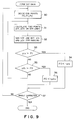
step 26 is shown in Fig. 9. The endpoint deciding section 6 decides end points of the respective straight lines which constitute the character outlines, and theDDA calculating section 7 takes any given end point p0 and a pair of two end points p1 and p2 adjacent to the end point p0 (in step 30) and extends two straight lines from the noticeable end point p0 toward the two end points p1 and p2 (in step 32). At the same time as the straight line extension execution, the straightline generating section 8 generates a straight line composed of dots between two interpolated points p1n and p2n at the extreme ends of the two extension lines and further executes NAND calculation of these straight lines (in step 32). The discriminating section 11 discriminates whether the extreme ends p1n and p2n of the extension lines reach the end points p1 and p2. If either of the extreme ends p1n and p2n of the straight lines reaches the end point p1 or p2 (instep 33 or 35), an extreme end point of a straight line which does not reach the end point is determined as the subsequent noticeable end point p0 (instep 34 or 36). - The above procedure is executed for all the outline information to generate dot signals corresponding to the character pattern (in step 37).
- As described above, it is possible to directly obtain dot signals indicative of the character pattern on the basis of outline information described by only straight lines.
- Without being limited to the above-mentioned embodiment, the present invention can be embodied in various modifications.
Claims (6)
- A method of generating dot signals corresponding to a character pattern on the basis of outline information described by only straight lines constituting outlines of the character pattern, comprising the steps of:
a first step of deciding end points of the straight lines constituting the character pattern outlines;
a second step of selecting one noticeable end point and two end points adjacent to the selected noticeable end point from the decided end points, and continuously generating a pair of points constituting two straight lines, respectively in such a way that the two straight lines can be extended from the selected noticeable end point toward the two adjacent end points; and
a third step of generating a straight line composed of dot signals between a pair of the generated points, respectively so that the generated dot signals correspond to the character pattern. - The method of claim 1, wherein in the second step, the two straight lines are extended until either one of the two straight lines extended from the noticeable end point reaches one of the adjacent end points; when either one of the two straight lines reaches the corresponding adjacent end point, a subsequent noticeable end point and two end points adjacent to the subsequent noticeable end point are newly selected in such a way that the subsequent noticeable end point is selected from the two straight line arrival points and end points not yet selected as a noticeable end point in the already decided end points; and new two straight lines are extended from the newly selected noticeable end point to two end points adjacent thereto.
- The method of claim 2, which further comprises a fourth step of NANDing the dot signals newly generated in the third step and the dot signals previously generated so that the NANDed output signals correspond to the character pattern.
- A system of generating dot signals corresponding to a character pattern on the basis of outline information described by only straight lines constituting outlines of the character pattern, comprising:
first means for deciding end points of the straight lines constituting the character pattern outlines;
second means for selecting one noticeable end point and two end joints adjacent to the selected noticeable end point from the decided end points, and continuously generating information indicative of a pair of points constituting two straight lines, respectively in such a way that two straight lines can be extended from the selected noticeable end point toward the two adjacent end points;
third means responsive to the information indicative of a pair of the points from said second means, for generating a straight line composed of dot signals between a pair of the respective generated points so that the dot signals generated by said third means correspond to the character pattern. - The system of claim 4, which further comprises
fourth means for detecting whether either one of the two extended straight lines reaches the adjacent end point; in response to an output from said fourth means, said second means newly selecting a subsequent noticeable end point and two end points adjacent to the subsequent noticeable end point in such a way that the subsequent noticeable end point is selected from the arrival points of the two extending straight lines and end points not yet selected as a noticeable end point in the already decided end points, and extending two new straight lines from the newly selected noticeable end point to the two adjacent end points. - The system of claim 5, which further comprises:
fifth means for storing dot signals corresponding to the character pattern;
sixth means responsive to the dot signals generated by said third means, for NANDing the dot signals generated by said third means and the dot signals already stored in said fifth means; and
signals outputted from said sixth means being stored in said fifth means as dot signals corresponding to the character pattern.
Applications Claiming Priority (3)
| Application Number | Priority Date | Filing Date | Title |
|---|---|---|---|
| JP46362/90 | 1990-02-27 | ||
| JP4636290 | 1990-02-27 | ||
| PCT/JP1991/000261 WO1991013427A1 (en) | 1990-02-27 | 1991-02-27 | Method of generating dot signal corresponding to character pattern and device therefor |
Publications (3)
| Publication Number | Publication Date |
|---|---|
| EP0471849A1 true EP0471849A1 (en) | 1992-02-26 |
| EP0471849A4 EP0471849A4 (en) | 1992-09-30 |
| EP0471849B1 EP0471849B1 (en) | 1995-06-07 |
Family
ID=12745043
Family Applications (1)
| Application Number | Title | Priority Date | Filing Date |
|---|---|---|---|
| EP91904796A Expired - Lifetime EP0471849B1 (en) | 1990-02-27 | 1991-02-27 | Method of generating dot signal corresponding to character pattern and device therefor |
Country Status (5)
| Country | Link |
|---|---|
| US (1) | US5355448A (en) |
| EP (1) | EP0471849B1 (en) |
| DE (1) | DE69110213T2 (en) |
| HK (1) | HK4997A (en) |
| WO (1) | WO1991013427A1 (en) |
Families Citing this family (8)
| Publication number | Priority date | Publication date | Assignee | Title |
|---|---|---|---|---|
| JPH0723997B2 (en) * | 1990-08-24 | 1995-03-15 | 富士ゼロックス株式会社 | Character / graphic drawing device |
| EP0564202B1 (en) * | 1992-03-30 | 2000-01-26 | Canon Kabushiki Kaisha | Image output method and apparatus with cache memory |
| EP0604685A1 (en) * | 1992-12-28 | 1994-07-06 | Océ-Nederland B.V. | Method of modifying the fatness of characters |
| DE4341367C1 (en) * | 1993-12-04 | 1995-06-14 | Harald Dr Med Dr Med Eufinger | Process for the production of endoprostheses |
| EP0661669B1 (en) * | 1993-12-30 | 2001-02-28 | Canon Kabushiki Kaisha | Character processing apparatus and method |
| JP2958396B2 (en) * | 1995-12-20 | 1999-10-06 | 富士ゼロックス株式会社 | Image forming device |
| US20060185233A1 (en) * | 2005-02-10 | 2006-08-24 | Joseph Sporta | Decorative structural supports |
| JP4367511B2 (en) * | 2007-03-26 | 2009-11-18 | セイコーエプソン株式会社 | Character drawing device, display device, and printing device |
Citations (2)
| Publication number | Priority date | Publication date | Assignee | Title |
|---|---|---|---|---|
| EP0293698A2 (en) * | 1987-05-20 | 1988-12-07 | Nec Corporation | Graphic controller having function of painting designated area |
| JPH1191192A (en) * | 1997-09-22 | 1999-04-06 | Shibaura Mechatronics Corp | Thermal transfer type recording apparatus |
Family Cites Families (8)
| Publication number | Priority date | Publication date | Assignee | Title |
|---|---|---|---|---|
| US4199815A (en) * | 1978-05-12 | 1980-04-22 | Electra Corporation | Typesetter character generating apparatus |
| JPS5971093A (en) * | 1982-10-18 | 1984-04-21 | 株式会社日立製作所 | Smeared graphic generator |
| JPS59188761A (en) * | 1983-04-08 | 1984-10-26 | Fujitsu Ltd | Write system of picture memory |
| US4675830A (en) * | 1984-07-06 | 1987-06-23 | Compugraphic Corporation | Method for producing a scaleable typeface data |
| JPH01191192A (en) * | 1988-01-27 | 1989-08-01 | Toshiba Corp | High quality character generating device |
| US5148519A (en) * | 1988-02-04 | 1992-09-15 | Ascii Corporation | Method for generating patterns based on outline data |
| JP2681367B2 (en) * | 1988-05-24 | 1997-11-26 | 株式会社日立製作所 | Graphic processing method and apparatus thereof |
| JP2659557B2 (en) * | 1988-07-27 | 1997-09-30 | 株式会社日立製作所 | Drawing system and drawing method |
-
1991
- 1991-02-27 WO PCT/JP1991/000261 patent/WO1991013427A1/en active IP Right Grant
- 1991-02-27 EP EP91904796A patent/EP0471849B1/en not_active Expired - Lifetime
- 1991-02-27 DE DE69110213T patent/DE69110213T2/en not_active Expired - Fee Related
- 1991-02-27 US US07/768,878 patent/US5355448A/en not_active Expired - Lifetime
-
1997
- 1997-01-09 HK HK4997A patent/HK4997A/en not_active IP Right Cessation
Patent Citations (2)
| Publication number | Priority date | Publication date | Assignee | Title |
|---|---|---|---|---|
| EP0293698A2 (en) * | 1987-05-20 | 1988-12-07 | Nec Corporation | Graphic controller having function of painting designated area |
| JPH1191192A (en) * | 1997-09-22 | 1999-04-06 | Shibaura Mechatronics Corp | Thermal transfer type recording apparatus |
Non-Patent Citations (3)
| Title |
|---|
| PATENT ABSTRACTS OF JAPAN vol. 13, no. 480 (P-952) 31 October 1989 & JP-A-11091192 * |
| PATENT ABSTRACTS OF JAPAN vol. 13, no. 480 (P-952)31 October 1989 * |
| See also references of WO9113427A1 * |
Also Published As
| Publication number | Publication date |
|---|---|
| WO1991013427A1 (en) | 1991-09-05 |
| DE69110213D1 (en) | 1995-07-13 |
| HK4997A (en) | 1997-01-17 |
| EP0471849B1 (en) | 1995-06-07 |
| EP0471849A4 (en) | 1992-09-30 |
| US5355448A (en) | 1994-10-11 |
| DE69110213T2 (en) | 1995-10-26 |
Similar Documents
| Publication | Publication Date | Title |
|---|---|---|
| US4153897A (en) | Method and device for detecting the similarity between standard and unknown patterns | |
| EP0549505A2 (en) | Method of and apparatus for optical character recognition based on geometric and color attribute hypothesis testing | |
| WO1990001198A1 (en) | Character recognition apparatus | |
| EP0471849B1 (en) | Method of generating dot signal corresponding to character pattern and device therefor | |
| US5524198A (en) | Character or graphic processing method and apparatus | |
| US6266444B1 (en) | Character processing apparatus and method therefor | |
| US5189730A (en) | Apparatus for generating character pattern signals and method for generating same | |
| US5388166A (en) | Image drawing apparatus | |
| JP2002099911A (en) | Raster image vector conversion method based on computerized automation | |
| EP0397348B1 (en) | Dot pattern signal generator | |
| EP0559353B1 (en) | Computer input apparatus and method for drawing free curves | |
| JPS6365151B2 (en) | ||
| US5878194A (en) | Method and device for outputting multicolor document | |
| JP2937508B2 (en) | Bitmap expansion method | |
| JP2989604B2 (en) | Pattern restoration method | |
| JPH0830725A (en) | Device and method for processing image | |
| JP3294249B2 (en) | Image processing device | |
| JP2715930B2 (en) | Line detection method | |
| JP2740506B2 (en) | Image recognition method | |
| JPH0691938A (en) | Printing control device | |
| CN114792376A (en) | Line segment endpoint extraction method | |
| JP3071479B2 (en) | Line spacing detection method | |
| JPH01210355A (en) | Character pattern generation | |
| JPS61158394A (en) | Fast circle circular arc generation system | |
| JPS5943486A (en) | Processing system for extracting circle |
Legal Events
| Date | Code | Title | Description |
|---|---|---|---|
| PUAI | Public reference made under article 153(3) epc to a published international application that has entered the european phase |
Free format text: ORIGINAL CODE: 0009012 |
|
| 17P | Request for examination filed |
Effective date: 19911026 |
|
| AK | Designated contracting states |
Kind code of ref document: A1 Designated state(s): DE FR GB |
|
| A4 | Supplementary search report drawn up and despatched |
Effective date: 19920813 |
|
| AK | Designated contracting states |
Kind code of ref document: A4 Designated state(s): DE FR GB |
|
| 17Q | First examination report despatched |
Effective date: 19940502 |
|
| GRAA | (expected) grant |
Free format text: ORIGINAL CODE: 0009210 |
|
| AK | Designated contracting states |
Kind code of ref document: B1 Designated state(s): DE FR GB |
|
| REF | Corresponds to: |
Ref document number: 69110213 Country of ref document: DE Date of ref document: 19950713 |
|
| ET | Fr: translation filed | ||
| PLBE | No opposition filed within time limit |
Free format text: ORIGINAL CODE: 0009261 |
|
| STAA | Information on the status of an ep patent application or granted ep patent |
Free format text: STATUS: NO OPPOSITION FILED WITHIN TIME LIMIT |
|
| 26N | No opposition filed | ||
| REG | Reference to a national code |
Ref country code: GB Ref legal event code: IF02 |
|
| PGFP | Annual fee paid to national office [announced via postgrant information from national office to epo] |
Ref country code: GB Payment date: 20080227 Year of fee payment: 18 Ref country code: DE Payment date: 20080221 Year of fee payment: 18 |
|
| PGFP | Annual fee paid to national office [announced via postgrant information from national office to epo] |
Ref country code: FR Payment date: 20080208 Year of fee payment: 18 |
|
| GBPC | Gb: european patent ceased through non-payment of renewal fee |
Effective date: 20090227 |
|
| REG | Reference to a national code |
Ref country code: FR Ref legal event code: ST Effective date: 20091030 |
|
| PG25 | Lapsed in a contracting state [announced via postgrant information from national office to epo] |
Ref country code: DE Free format text: LAPSE BECAUSE OF NON-PAYMENT OF DUE FEES Effective date: 20090901 |
|
| PG25 | Lapsed in a contracting state [announced via postgrant information from national office to epo] |
Ref country code: GB Free format text: LAPSE BECAUSE OF NON-PAYMENT OF DUE FEES Effective date: 20090227 Ref country code: FR Free format text: LAPSE BECAUSE OF NON-PAYMENT OF DUE FEES Effective date: 20090302 |