EP0471371A2 - Displacement-measuring apparatus - Google Patents
Displacement-measuring apparatus Download PDFInfo
- Publication number
- EP0471371A2 EP0471371A2 EP91113693A EP91113693A EP0471371A2 EP 0471371 A2 EP0471371 A2 EP 0471371A2 EP 91113693 A EP91113693 A EP 91113693A EP 91113693 A EP91113693 A EP 91113693A EP 0471371 A2 EP0471371 A2 EP 0471371A2
- Authority
- EP
- European Patent Office
- Prior art keywords
- contact pressure
- probe shaft
- stylus
- section
- bush
- Prior art date
- Legal status (The legal status is an assumption and is not a legal conclusion. Google has not performed a legal analysis and makes no representation as to the accuracy of the status listed.)
- Granted
Links
Images


Classifications
-
- F—MECHANICAL ENGINEERING; LIGHTING; HEATING; WEAPONS; BLASTING
- F16—ENGINEERING ELEMENTS AND UNITS; GENERAL MEASURES FOR PRODUCING AND MAINTAINING EFFECTIVE FUNCTIONING OF MACHINES OR INSTALLATIONS; THERMAL INSULATION IN GENERAL
- F16C—SHAFTS; FLEXIBLE SHAFTS; ELEMENTS OR CRANKSHAFT MECHANISMS; ROTARY BODIES OTHER THAN GEARING ELEMENTS; BEARINGS
- F16C32/00—Bearings not otherwise provided for
- F16C32/04—Bearings not otherwise provided for using magnetic or electric supporting means
-
- G—PHYSICS
- G01—MEASURING; TESTING
- G01B—MEASURING LENGTH, THICKNESS OR SIMILAR LINEAR DIMENSIONS; MEASURING ANGLES; MEASURING AREAS; MEASURING IRREGULARITIES OF SURFACES OR CONTOURS
- G01B3/00—Measuring instruments characterised by the use of mechanical techniques
- G01B3/002—Details
- G01B3/008—Arrangements for controlling the measuring force
-
- G—PHYSICS
- G01—MEASURING; TESTING
- G01B—MEASURING LENGTH, THICKNESS OR SIMILAR LINEAR DIMENSIONS; MEASURING ANGLES; MEASURING AREAS; MEASURING IRREGULARITIES OF SURFACES OR CONTOURS
- G01B5/00—Measuring arrangements characterised by the use of mechanical techniques
- G01B5/004—Measuring arrangements characterised by the use of mechanical techniques for measuring coordinates of points
- G01B5/008—Measuring arrangements characterised by the use of mechanical techniques for measuring coordinates of points using coordinate measuring machines
- G01B5/012—Contact-making feeler heads therefor
-
- G—PHYSICS
- G01—MEASURING; TESTING
- G01B—MEASURING LENGTH, THICKNESS OR SIMILAR LINEAR DIMENSIONS; MEASURING ANGLES; MEASURING AREAS; MEASURING IRREGULARITIES OF SURFACES OR CONTOURS
- G01B7/00—Measuring arrangements characterised by the use of electric or magnetic techniques
- G01B7/002—Constructional details of contacts for gauges actuating one or more contacts
-
- G—PHYSICS
- G01—MEASURING; TESTING
- G01B—MEASURING LENGTH, THICKNESS OR SIMILAR LINEAR DIMENSIONS; MEASURING ANGLES; MEASURING AREAS; MEASURING IRREGULARITIES OF SURFACES OR CONTOURS
- G01B7/00—Measuring arrangements characterised by the use of electric or magnetic techniques
- G01B7/004—Measuring arrangements characterised by the use of electric or magnetic techniques for measuring coordinates of points
- G01B7/008—Measuring arrangements characterised by the use of electric or magnetic techniques for measuring coordinates of points using coordinate measuring machines
- G01B7/012—Contact-making feeler heads therefor
-
- Y—GENERAL TAGGING OF NEW TECHNOLOGICAL DEVELOPMENTS; GENERAL TAGGING OF CROSS-SECTIONAL TECHNOLOGIES SPANNING OVER SEVERAL SECTIONS OF THE IPC; TECHNICAL SUBJECTS COVERED BY FORMER USPC CROSS-REFERENCE ART COLLECTIONS [XRACs] AND DIGESTS
- Y10—TECHNICAL SUBJECTS COVERED BY FORMER USPC
- Y10S—TECHNICAL SUBJECTS COVERED BY FORMER USPC CROSS-REFERENCE ART COLLECTIONS [XRACs] AND DIGESTS
- Y10S33/00—Geometrical instruments
- Y10S33/02—Air
-
- Y—GENERAL TAGGING OF NEW TECHNOLOGICAL DEVELOPMENTS; GENERAL TAGGING OF CROSS-SECTIONAL TECHNOLOGIES SPANNING OVER SEVERAL SECTIONS OF THE IPC; TECHNICAL SUBJECTS COVERED BY FORMER USPC CROSS-REFERENCE ART COLLECTIONS [XRACs] AND DIGESTS
- Y10—TECHNICAL SUBJECTS COVERED BY FORMER USPC
- Y10S—TECHNICAL SUBJECTS COVERED BY FORMER USPC CROSS-REFERENCE ART COLLECTIONS [XRACs] AND DIGESTS
- Y10S33/00—Geometrical instruments
- Y10S33/13—Wire and strain gauges
Abstract
Description
- The present invention relates to a displacement-measuring apparatus which has a stylus movable relative to an object for detecting the shape of the object, and also to a static-pressure bearing device designed for use in the displacement-measuring apparatus.
- A displacement-measuring apparatus for detecting the shapes of objects has an air bearing, a probe shaft, and a stylus. The air bearing supports the probe shaft, not contacting the shaft, such that the shaft can move in its axial direction. The stylus is attached to the distal end of the probe shaft, and put in rolling contact with an object, applying a predetermined contact pressure thereto. As the object is rotated, the stylus set in rolling contact moves back and forth in its axial direction. The stroke of the stylus is transmitted to and detected by the probe shaft.
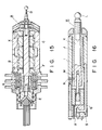
- Fig. 15 shows a conventional displacement-measuring apparatus A, which comprises a cylindrical housing X, an air bearing B located within the housing X, and a probe shaft C supported by the bearing B. The air bearing B has a through hole extending in its axial direction and having a rectangular cross section. The probe shaft C has a rectangular cross section and is loosely fitted in the through hole of the bearing B, such that it can move along its axis but cannot rotate around its axis.
- The apparatus A further comprises a stylus D, a corner cube E, a core F, and a bias coil G. The stylus D is connected to the distal end of the probe shaft C. The core F is a hollow cylinder mounted on the proximal end portion of the shaft C. The corner cube E is fastened to the core F and, hence, to the proximal end the probe shaft C, for detecting the displacement of the probe shaft C. The bias coil G is contained in the housing X and surrounds the core F, not contacting the core F.
- Fig. 16 shows another conventional displacement-measuring apparatus H, which comprises a cylindrical housing I, an air bearing J located within the housing I, and a probe shaft K supported by the air bearing J under static pressure. The apparatus H further comprises a stylus L and a pin N. The stylus L is attached to the distal end of the probe shaft K. The pin N is set in screw engagement in a screw hole made in the wall of the housing I and protrudes into a U-groove M which is cut in the outer periphery of the proximal end portion of the shaft K and which extends parallel to the axis of the shaft K.
- The air bearing J and the probe shaft K are spaced apart. Compressed air is supplied into the gap between the air bearing J and the shaft K from an air inlet port R through an air passage Q. The compressed air flows out of the gap and is discharged outside through an air outlet port S. The opening of the passage Q is adjusted by turning an adjustment screw (not shown).
- In the displacement-measuring apparatus A, the contact pressure the stylus D applies to the object is controlled by changing the current supplied to the bias coil G. The larger the current, the more heat the coil G generates. There is the possibility that the heat impairs the reliability of the data acquired by operating the apparatus A for a long period of time. To reduce this possibility, a heat-radiating mechanism can be added to the displacement-measuring apparatus A. The use of such a mechanism renders the apparatus A complex and large.
- The displacement-measuring apparatus A, shown in Fig. 15, has no sensors for the contact pressure applied from the stylus D to the object. Therefore, in the apparatus A it is impossible to adjust the current supplied to the bias coil G, minutely in accordance with slight changes in the contact pressure. This is detrimental to accurate detection of the shape of the object.
- Further, as has been described, the probe shaft C has a rectangular cross section and is loosely fitted in the through hole of the bearing B which has a can move along its axis, but cannot rotate around its axis. Obviously, more labor and time are required to fit a bearing bush into the gap between the through hole and the shaft C and adjust this gap, than to place a bush into the gap between a circular hole and a shaft having a circular cross section and adjust the gap.
- In the displacement-measuring apparatus H, shown in Fig. 16, the screw is turned to adjust the opening of the air passage Q. The rate at which the air flows outside through the air outlet port S is thereby controlled, thus adjusting the contact pressure the stylus L applies to the object. However, no measures are taken against changes in the characteristic of the air bearing J or changes in the contact pressure.
- The pin N set in screw engagement in a hole made in the wall of the housing I is loosely fitted in the U-groove M cut in the outer periphery of the shaft K and extending along the axis of the shaft K. Hence, the pin N prevents the probe shaft K from rotating around its axis. The pin N hinders smooth moving of the shaft K. Due to the friction between the pin N and the shaft K, the shaft K may fail to move faithfully to the motion of the stylus L.
- Accordingly, the object of the present invention is to provide a displacement-measuring apparatus in which a little heat, if any, is generated, and the contact pressure applied to an object scarcely changes.
- According to the invention, there is provided a displacement-measuring apparatus comprising: a cylindrical housing; a static-pressure bearing located in the housing; a probe shaft supported by the bearing in non-contact fashion and movable in an axial direction; a stylus connected to one end of the probe shaft, for applying a contact pressure to an object; a pressure-adjusting section for adjusting the contact pressure applied from the stylus to the object; a pressure-detecting section for detecting the contact pressure applied from the stylus to the object; and a pressure-controlling section for generating a control signal in accordance with the contract pressure detected by the pressure-detecting section and supplying the control signal to the pressure-adjusting section, thereby to control the contact pressure.
- In operation, the pressure-detecting section detects the contact pressure the stylus applies to the object. In accordance with the contact pressure thus detected, the pressure-adjusting section controls the contact pressure in real time. Hence, the contact pressure is minutely controlled, faithfully to slight changes in the contact pressure. Since the pressure-adjusting section generates virtually no heat, the apparatus can measure the displacement of the object with high accuracy.
- This invention can be more fully understood from the following detailed description when taken in conjunction with the accompanying drawings, in which:
- Fig. 1 shows a displacement-measuring apparatus according to a first embodiment of the invention;
- Fig. 2 is a cross-sectional view showing the contact pressure detecting section of the apparatus shown in Fig. 1;
- Fig. 3 shows a displacement-measuring apparatus according to a second embodiment of the invention;
- Fig. 4 is a cross-sectional view of a pressure adjusting section;
- Fig. 5 is a sectional view, taken along line V-V in Fig. 4;
- Fig. 6 is a graph representing the relation between magnetic attraction and inter-magnet distance, and explaining the operating characteristic of the apparatus shown in Fig. 3;
- Fig. 7 shows a displacement-measuring apparatus according to a third embodiment of the invention;
- Fig. 8 is an enlarged view showing a part of the apparatus shown in Fig. 7;
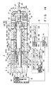
- Fig. 9 is a diagram showing a displacement-measuring apparatus according to a fourth embodiment of the invention;
- Fig. 10 shows a displacement-measuring apparatus according to a fifth embodiment of the invention;
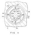
- Fig. 11 is a cross-sectional view, taken along line VI-VI in Fig. 10;
- Figs. 12 and 13 are diagrams explaining how the apparatus of Fig. 10 performs its function;
- Fig. 14 shows a displacement-measuring apparatus according to a sixth embodiment of the invention;
- Fig. 15 is a cross-sectional view showing a conventional displacement-measuring apparatus; and
- Fig. 16 is a cross-sectional view showing another conventional displacement-measuring apparatus.
- Embodiments of the present invention will now be described, with reference to the accompanying drawings.
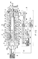
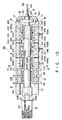
- Fig. 1 shows a displacement-measuring apparatus P1 according to a first embodiment of the invention. The apparatus P1 comprises a
cylindrical housing 1, an air bearing 2 (i.e., a static-pressure bearing) located in thehousing 1, and aprobe shaft 3 supported in non-contact fashion by thebearing 2, having a circular cross section and able to move in its axial direction. - The displacement-measuring apparatus P1 further comprises a
stylus 4, astopper 5, and
a length-measuring section 6. Thestylus 4 is connected to the distal end of theprobe shaft 3 and positioned coaxial with theshaft 3. It is set in direct contact with an object in order to measure the displacement of the object. Thestopper 5 is arranged between theshaft 3 and thestylus 4, for restricting the axial movement of theprobe shaft 3. The length-measuring section 6 is attached to the proximal end of theprobe shaft 3. Thesection 6 has acorner cube 6a which is designed to detect the displacement of theprobe shaft 3. - The apparatus P1 has a contact-pressure adjusting
section 7, a contact-pressure detecting section 8, and a contact-pressure controlling section 9. Thesection 7 is located in the proximal end portion of thehousing 1 and mounted on theprobe shaft 3. Thesection 8 is located between theshaft 3 and thestopper 5, for detecting the contact pressure applied from thestylus 4 to the object and generating an electric signal representing the pressure detected. Thesection 9 is an electric device for generating a control signal from the signal generated by the contactpressure detecting section 8 and supplying the control signal to the contactpressure adjusting section 7. - The
housing 1 comprises fiveparts 10 to 14. Thefirst part 10 surrounds thecorner cube 6a and positioned coaxial therewith. Thesecond part 11 is couple to thefirst part 10 and holds the contactpressure adjusting section 7. Thethird part 12 is connected to thesecond part 11 and holds theair bearing 2. Thefourth part 13 is connected to thethird part 12, surrounds the contactpressure detecting section 8, and located coaxial therewith. Thefifth part 14 is coupled to thefourth part 13, loosely holds thestopper 5, and positioned coaxial therewith. - The
fifth part 14 of thehousing 1 comprises acylindrical section 15 and anend plate 16 closing the distal end of thecylindrical section 15. Thecylindrical section 15 has a taperedcircumferential surface 16a. A throughhole 18 is formed in thecylindrical section 15 and opens at one end in thesurface 16a and at the other end at the inner surface. A throughhole 17 is formed in theend plate 16, coaxial with thestopper 5. - The
air bearing 2 is formed of a hollowcylindrical metal bush 19. Twoannular guide grooves 20 are cut in the outer circumferential surface of thebush 19. Restriction holes 21 are made in the bottom of either guidegroove 20, narrowing toward, and opening at, the inner circumferential surface of thebush 19. Outlet holes 22 are made in that thick-wall portion of thebush 19 which is located between theannular guide grooves 20. Theholes 22 are equidistantly spaced part around the circumference of thebush 19. Compressed air is jetted from thegrooves 20 via the restriction holes 21 into the interior of theair bearing 2. The air is discharged from thebush 19 through the outlet holes 22. - Another set of
outlet holes 22a are made in thethird part 12 of thehousing 1 and positioned coaxial with the outlet holes 22 of themetal bush 19. Thethird part 12 has twoinlet holes 24 which communicate with theannular guide grooves 20 of thebush 19. It is through these inlet holes 24 that compressed air is supplied to theguide groove 20 and ultimately into the interior of theair bearing 2. Both inlet holes 24 are connected to a source of compressed air (not shown). - The
stopper 5 is comprised of ashaft 25 and aflange 26. Theshaft 25 is coupled to theprobe shaft 3 and is coaxial therewith. Its distal end portion protrudes from the distal end of thehousing 1, extending through thehole 17 of theend plate 16. Theflange 26 is mounted on the middle portion of theshaft 25. Theflange 26 can move in the axial direction of theprobe shaft 3 in the space between thefourth part 13 of thehousing 1 and theend plate 16. Hence, thestopper 5 can move back and forth, for the distance between thehousing part 13 and theend plate 16. - The
stylus 4 comprises amain shaft 27 and aruby ball 28. The main shaft has a pointed distal end. Theruby ball 28 is connected to the pointed end of themain shaft 27. - The length-measuring
section 6 comprises thecorner cube 6a and a laser interferometry length-measuringdevice 32. Thecorner cube 6a has a tworeflection surfaces surfaces 29a and 29 incline at 45° to the axis of theprobe shaft 3 and intersect at 90° with each other. The laser interferometry length-measuringdevice 32 applies alaser beam 30 to thefirst reflection surface 29a along the axis of theprobe shaft 3, and detects the displacement of theprobe shaft 3 from the interference characteristic of thelaser beam 31 reflected by bothreflection surfaces device 32 along the axis of theshaft 3. - The contact
pressure adjusting section 7 comprises a hollow cylindrical bobbin 33, a pair ofpermanent magnets coils cylindrical core 38. Thecore 38 is mounted on theprobe shaft 3. The bobbin 33 surrounds thecore 38 and has two annular U-grooves cut in its outer circumferential surface. Themagnets coils magnets - Electric power is supplied to the
coils magnet 34 and thecoil 36, and also changing the magnetic force generated between themagnet 35 and thecoil 37. When supplied with electric power, either coil generates heat. Nonetheless, the heat is radiated effectively from thesecond part 11 of thehousing 1 since heat-radiatingannular fins 39 are mounted on thesecond housing part 11. - When electric power is supplied to neither the
coil 36 nor thecoil 37, the magnetic force generated between the core 38 and themagnets probe shaft 3 to the right, whereby thestylus 4 applies a permanent contact pressure PO to an object. When electric power is supplied to thecoils coils magnets - As is best shown in Fig. 2, the contact
pressure detecting section 8 comprises an elasticsolid cylinder 40 and strain detecting means 41 (such as strain gauges). Theelastic cylinder 40 is clamped between theprobe shaft 3 and theshaft 25 of thestopper 5 and positioned coaxial therewith. The strain gauges 41 are bonded on the circumferential surface of thecylinder 40 and equidistantly spaced part along the circumference of thecylinder 40. The strain gauges 41 generates displacement signals SA of the voltages which represent the strain applied to theelastic cylinder 40. Thefourth housing part 13, which surrounds theelastic cylinder 40, has throughholes 42 which extend in radial direction of thepart 13. Wires extend through theseholes 42 and connected at one end to the strain gauges 41. - The contact
pressure controlling section 9 comprises anamplifier 43, afirst operation unit 44, a contactpressure setting unit 45, acontrol unit 48,amplifiers second operation unit 51. Theamplifier 43 is electrically connected by the wires to the strain gauges 41, for amplifying the displacement signals SA generated by the strain gauges 41. Thefirst operation unit 44 is connected to the output of theamplifier 43. Theunit 44 receives the amplified displacement signals SB from theamplifier 43 and calculates, from the signals SB, the strain along the axis of theelastic cylinder 40 which is proportional to the contact pressure P in terms of contact pressure P. Theunit 44 also calculates the inclination of thecylinder 40 with respect to the axis of theprobe shaft 3. - The contact
pressure setting unit 45 is operated to set a desired contact pressure, i.e., a target contact pressure PA. Thecontrol unit 48 receives an electric signal SC output by theunit 44, and also an electric signal SD output by theunit 45. The signal SC represents both the pressure P calculated by theunit 44 and the inclination ΔT. Theunit 48 outputs two control signals SE and SF for eliminating the difference ΔP between the target contact pressure PA set by theunit 35 and the contact pressure P detected by thesection 8. - The
amplifiers control unit 48, respectively. The signals SE and SF, thus amplified, are supplied to thecoils second operation unit 51 receives the signal SC and a displacement signal SG. The signal SC output by thefirst operation unit 44 represents the contact pressure P and the inclination ΔT, as has been described. The displacement signal SG has been output by the laser interferometry length-measuringdevice 32 and represents the displacement of theprobe shaft 3. Thesecond operation unit 51 calculates the actual displacement of theprobe shaft 3 from the strain ε and the inclination ΔT. - The operation of the displacement-measuring apparatus P1 described above will now be explained.
- First, compressed air is supplied into the
annular guide grooves 20 through the inlet holes 24. The air is further supplied into the gap between theprobe shaft 3 and thehousing 1 via the restriction holes 21 made in the bottoms of theguide grooves 20. As a result, theair bearing 2 supports theprobe shaft 3 in non-contact fashion, positioning theshaft 3 coaxial with thehousing 1. The compressed air jetting through the restriction holes 21 is discharged from the apparatus P1 through the outlet holes 22 of themetal bush 19, the outlet holes 22a of thethird housing part 12, and finally through thehole 17 of thefifth housing part 14 and the throughholes 42 of thefourth housing part 13. - Next, the apparatus P1 is positioned, bringing the
stylus 4 into contact with an object. At this time, the contactpressure controlling section 9 and the length-measuringdevice 32 are already operative. Thedevice 32 applies alaser beam 30 to thefirst reflection surface 29a of thecorner cube 6a, receives thelaser beam 31 reflected from thesecond reflection surface 29b of thecorner cube 6a, and measures the displacement of theprobe shaft 3. Meanwhile, a predetermined power is supplied to thecoils pressure adjusting section 7. - When the
stylus 4 contacts the object, theprobe shaft 3 tends to move backwards, in the direction ofarrow 52a as is shown in Fig. 1. However, it is pushed forward in the direction ofarrow 52b, due to the magnetic force generated between the core 38 and thepermanent magnets coils stylus 4 applies a contact pressure to the object, giving a strain to theelastic cylinder 40 and, hence, deforming thecylinder 40. - Then, the strain gauges 41 bonded to the circumferential surface of the
elastic cylinder 40 generate displacement signals SA, each representing the voltage equivalent to the strain thegauge 41 detects. These signals SA are supplied to the contactpressure controlling section 9. In thesection 9, theamplifier 43 amplifies the signals SA and outputs signals SB, which are supplied to thefirst operation unit 44. Theunit 44 calculates the strain along the axis of theelastic cylinder 40 which is proportional to the contact pressure P, and also determines the inclination ΔT of thecylinder 40 with respect to the axis of theprobe shaft 3, and generates an electric signal SC which represents both the contact pressure P and the inclination ΔT. - In the meantime, the contact
pressure setting unit 45 sets a target contact pressure PA which thestylus 4 should apply to the object, and outputs a target-pressure signal SD. Thecontrol unit 48 receives the target-pressure signal SD and also the electric signal SC output by thefirst operation unit 44. Theunit 48 outputs two control signals SE and SF for eliminating the difference ΔP between the target contact pressure PA set by theunit 35 and the contact pressure P. The control signals SE and SF are input to theamplifiers control unit 48, respectively. The outputs of theamplifiers coils - In accordance with the magnitudes of the signals SE' and SF', the
coils permanent magnets stylus 4 to the object increases from the permanent value PO to the target value PA. - The feedback control described above is performed in real time, throughout the displacement-measuring operation.
- Meanwhile, the
second operation unit 51 receives the signal SC output by thefirst operation unit 44 and the displacement signal SG supplied by the length-measuringdevice 32. As has been described, the signal SC represents the contact pressure P and the inclination ΔT of theelastic cylinder 40, whereas the signal SG represents the displacement of theprobe shaft 3. From these input signals SC and SG, which represent the strain ε along the axis of thecylinder 40 and the inclination ΔT thereof, thesecond operation unit 51 calculates the actual displacement of theprobe shaft 3, and generates data representing the actual displacement of theshaft 3. This data is supplied to a display (not shown), whereby the actual displacement of theprobe shaft 3 is monitored. - As has been explained, in the displacement-measuring apparatus P1 (Fig. 1), the contact
pressure detecting section 8 detects the contact pressure applied from thestylus 4 to the object, and the contactpressure adjusting section 7 is controlled in accordance with the contact pressure thus detected, thereby to change the pressure to a target value. Hence, the contact pressure applied from the stylus to the object is adjusted in real time. - As as been described, the contact pressure applied to the object results not only from the magnetic force generated between the core 38 and the
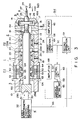
coils permanent magnets coils permanent magnets coils probe shaft 3 with high precision. The apparatus P1 can therefore have high displacement-measuring accuracy. - Fig. 3 shows a displacement-measuring apparatus P2 according to a second embodiment of the invention. Some of the components of this apparatus P2 are identical to the corresponding components of the apparatus P1 (i.e., the first embodiment of the invention). Therefore, they are designated by the same numerals in Fig. 3, and will not be described in detail.
- As is shown in Figs. 4 and 5, the contact pressure adjusting section 7-1 of the apparatus P2 comprises three
spacers 61 made of non-magnetic material, threepiezoelectric actuators 62 each being a laminate of plates, three plate-like yokes 63 made of ferromagnetic material, three pairs ofpermanent magnets 64, and three pairs ofpermanent magnets 65. - The
spacers 61 are secured to the inner circumferential surface of asecond part 11 of ahousing 1, and are equidistantly spaced apart along the circumference of thehousing 1. Thepiezoelectric actuators 62 are connected to thespacers 61, respectively. Theyokes 63 are fixed to thepiezoelectric actuators 62, respectively, and have each a curving surface defining a circle concentric to thehousing 1. Thepermanent magnets 64 of each pair, both bent gently along a circle concentric to thehousing 1, are connected to thecorresponding yoke 63. As is evident from Fig. 5, themagnets housing 1, with the N pole of thefirst magnet 64 opposing the S pole of thesecond magnet 65. The three pairs ofpermanent magnets 65 are mounted on the circumferential surface of theprobe shaft 3 located within thehousing 1 and coaxial therewith. These magnet pairs are equidistantly spaced apart along the circumference of theprobe shaft 3. Themagnets 65 of each pair are set apart from each other in a line parallel to the axis of theshaft 3, with the N pole of thefirst magnet 65 opposing the S pole of thesecond magnet 65. - The apparatus P2 comprises a contact pressure controlling section 9-1. The section 9-1 is identical to the contact
pressure controlling section 9 of the apparatus P1 (Fig. 1), except that oneamplifier 68 is used in place of theamplifiers amplifier 68 is connected to thecontrol unit 48. - The
piezoelectric actuators 62 of the contact pressure adjusting section 7-1 are connected to theamplifier 68. When a voltage is applied to theactuators 62 from theamplifier 68, theactuators 62 expand or contract in the radial direction of thehousing 1. Eachpiezoelectric actuator 62 has been prepared by the following method. - First, a sintered ceramic mass is cut into plates. Then, the ceramic plates are processed. Next, the processed ceramic plates are laid one upon another. An electrode is coated on the uppermost plate, and another electrode is coated on the lowermost plate. Finally, the ceramic plates are adhered together or pressed bonded, forming a laminate of ceramic plates. Preferably, the ceramic is Pb(Zr, Ti)O₃ (PZT), PbTiO₃ (PT), or (Pb, La)(Zr, Ti)O₃ (PLZT).
- The
permanent magnets 64 of each pair are secured to thecorresponding yoke 63, such that the N pole of thefirst magnet 64 opposes the S pole of thesecond magnet 64 as is evident from Fig. 5. Similarly, thepermanent magnets 65 of each pair are arranged on theprobe shaft 3, such that the N pole of thefirst magnet 65 opposes the S pole of thesecond magnet 65 as is shown in Fig. 5. Therefore, the magnetic fluxes thesemagnets magnetic circuit 66 indicated by broken lines in Fig. 5. The gap between any pair of themagnets 64 and the corresponding pair ofmagnets 65 is adjusted as thepiezoelectric actuator 62 expands or contracts in the direction ofarrow 67. - The operation of the displacement-measuring apparatus P2 shown in Figs. 3, 4 and 5 will now be explained.
- First, compressed air is supplied from a source of compressed air (not shown) into the
annular guide grooves 20 through the inlet holes 24. The air is further supplied into the gap between theprobe shaft 3 and thehousing 1 via the restriction holes 21 made in the bottoms of theguide grooves 20. As a result, theair bearing 2 supports theprobe shaft 3 in non-contact fashion, positioning theshaft 3 coaxial with thehousing 1. The compressed air jetting through the restriction holes 21 is discharged from the apparatus P2 via the outlet holes 22 of themetal bush 19, the outlet holes 22a of thethird housing part 12, and finally through thehole 17 of thefifth housing part 14 and the throughholes 42 of thefourth housing part 13. - Next, the apparatus P2 is positioned, bringing the
stylus 4 into contact with an object. At this time, the contact pressure controlling section 9-1 and the length-measuringdevice 32 are already operative. Thedevice 32 applies alaser beam 30 to thefirst reflection surface 29a of thecorner cube 6a, receives thelaser beam 31 reflected from thesecond reflection surface 29b of thecorner cube 6a, and measures the displacement of theprobe shaft 3. Meanwhile, a predetermined power is supplied to thecoils - When the
stylus 4 contacts the object, theprobe shaft 3 tends to move backwards, in the direction ofarrow 52a as is shown in Fig. 3. However, it is pushed forward in the direction ofarrow 52b, due to the magnetic force generated between thepermanent magnets 64, on the one hand, and thepermanent magnets 65, on the other. As a result, thestylus 4 applies a contact pressure to the object, giving a strain to theelastic cylinder 40 and, hence, deforming thecylinder 40. - Then, the strain gauges 41 bonded to the circumferential surface of the
elastic cylinder 40 generate displacement signals SA, each representing the voltage equivalent to the strain thegauge 41 detects. These signals SA are supplied to the contact pressure controlling section 9-1. In the section 9-1, theamplifier 43 amplifies the signals SA and outputs signals SB, which are supplied to thefirst operation unit 44. Theunit 44 calculates the strain along the axis of theelastic cylinder 40 which is proportional to the con tact pressure P, and also determines the inclination ΔT of thecylinder 40 with respect to the axis of theprobe shaft 3, and generates an electric signal SC which represents both the contact pressure P and the inclination ΔT. - In the meantime, the contact
pressure setting unit 45 sets a target contact pressure PA which thestylus 4 should apply to the object, and outputs a target-pressure signal SD. Thecontrol unit 48 receives the target-pressure signal SD and also the electric signal SC output by thefirst operation unit 44. Theunit 48 outputs a control signal SH for eliminating the difference ΔP between the target contact pressure PA set by theunit 35 and the contact pressure P. The control signal SH is input to theamplifier 68, which amplifies the control signal SH output by thecontrol unit 48. The output of theamplifier 68, i.e., the amplified signal SH', is supplied to thepiezoelectric actuators 62 of the contact pressure adjusting section 7-1. - In accordance with the magnitude of the control signal SH', the
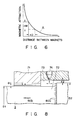
piezoelectric actuators 62 expand or contract in the direction ofarrows 67 as is shown in Fig. 5. As a result, the gap between any pair ofpermanent magnets 64 and the corresponding pair ofpermanent magnets 65 changes, whereby the magnetic attraction between the pairs of magnets changes in inverse proportion to the gap, as can be understood from the graph of Fig. 6. That is, the expansion or contraction of each actuator 62 is controlled by the control signal SH', thereby adjusting the contact pressure thestylus 4 applies to the object. - In Fig. 6, the magnetic attraction between the
magnets 64, on the one hand, and themagnets 65, on the other, is plotted on the vertical axis, where as the gap between these two sets of magnets is plotted on the horizontal axis. As is evident from Fig. 6, the magnetic attraction can be greatly changed by varying the gap a little, as long as the gap fall is a region where the slope of curve A is acute. - Meanwhile, the
second operation unit 51 receives the signal SC output by thefirst operation unit 44 and the displacement signal SG supplied by the length-measuringdevice 32. As has been described, the signal SC represents the contact pressure P and the inclination ΔT of theelastic cylinder 40, whereas the signal SG represents the displacement of theprobe shaft 3. From these input signals SC and SG, which represent the strain ε along the axis of thecylinder 40 and the inclination ΔT thereof, thesecond operation unit 51 calculates the actual displacement of theprobe shaft 3, and generates data representing the actual displacement of theshaft 3. This data is supplied to a display (not shown), whereby the actual displacement of theprobe shaft 3 is monitored. - As has been explained, in the apparatus P2 (Fig. 3), the contact
pressure detecting section 8 detects the contact pressure applied from thestylus 4 to the object, and the contact pressure adjusting section 7-1 is controlled in accordance with the contact pressure thus detected, thereby to change the pressure to a target value. Hence, the contact pressure applied from the stylus to the object is adjusted in real time. Further, since thepiezoelectric actuators 62 of the contact pressure adjusting section 7-1 can expand or contract very minutely in accordance with the voltage to the control signal SH' supplied to them, the contact pressure applied from thestylus 4 to the object can be adjusted with high precision. - The
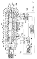
piezoelectric actuators 62 generate virtually no heat, comparing with a solenoid, when the control signal SH'' is supplied to them. Hence, this also enables the apparatus P2 to have a very high displacement-measuring accuracy. - Fig. 7 shows a displacement-measuring apparatus P3 according to a third embodiment of the present invention. Some of the components of this apparatus P2 are identical to the corresponding components of the apparatuses P1 and P3, and are therefore designated by the same numerals in Fig. 3 and will not be described in detail.
- As is shown in Fig. 7, the apparatus P3 comprises a
cylindrical housing 1, an air bearing 2 (i.e., a static-pressure bearing) located in thehousing 1, and aprobe shaft 3 supported in non-contact fashion by thebearing 2, having a circular cross section and able to move in its axial direction. - The displacement-measuring apparatus P3 further comprises a
stylus 4, astopper 5, and a length-measuringsection 6. Thestylus 4 is connected to the distal end of theprobe shaft 3 and positioned coaxial with theshaft 3. It is set in direct contact with an object in order to measure the displacement of the object. Thestopper 5 is arranged between theshaft 3 and thestylus 4, for restricting the axial movement of theprobe shaft 3. The length-measuringsection 6 is attached to the proximal end of theprobe shaft 3. Thesection 6 has acorner cube 6a which is designed to detect the displacement of theprobe shaft 3. - The apparatus P3 has a contact-pressure adjusting section 7-2, a contact-
pressure detecting section 8, and a contact-pressure controlling section 9-2. The section 7-2 is located in the proximal end portion of thehousing 1 and mounted on theprobe shaft 3. Thesection 8 is located between theshaft 3 and the stop per 5, for detecting the contact pressure applied from thestylus 4 to the object and generating an electric signal representing the pressure detected. The section 9-2 is an electric device for generating a control signal from the signal generated by the contactpressure detecting section 8 and supplying the control signal to the contact pressure adjusting section 7-2. - The
housing 1 comprises fiveparts 10 to 14. Thefirst part 10 surrounds thecorner cube 6a and positioned coaxial therewith. Thesecond part 11 is coupled to thefirst part 10 and holds the contact pressure adjusting section 7-2. Thethird part 12 is connected to thesecond part 11 and holds theair bearing 2. Thefourth part 13 is connected to thethird part 12, surrounds the contactpressure detecting section 8, and located coaxial therewith. Thefifth part 14 is coupled to thefourth part 13, loosely holds thestopper 5, and positioned coaxial therewith. Astopper 5 is loosely inserted in thefifth part 14 and located coaxial therewith. - The
air bearing 2 is formed of a hollowcylindrical metal bush 19. Twoannular guide grooves 20 are cut in the outer circumferential surface of thebush 19. Restriction holes 21 are made in the bottom of either guidegroove 20, narrowing toward, and opening at, the inner circumferential surface of thebush 19. Outlet holes 22 are made in that thick-wall portion of thebush 19 which is located between theannular guide grooves 20. Theholes 22 are equidistantly spaced part around the circumference of thebush 19. Compressed air is jetted from thegrooves 20 via the restriction holes 21 into the interior of theair bearing 2. The air is discharged from thebush 19 through the outlet holes 22. - Another set of
outlet holes 22a are made in thethird part 12 of thehousing 1 and positioned coaxial with the outlet holes 22 of themetal bush 19. Thethird part 12 has twoinlet holes 24 which communicate with theannular guide grooves 20 of thebush 19. It is through these inlet holes 24 that compressed air is supplied to theguide groove 20 and ultimately into the interior of theair bearing 2. Both inlet holes 24 are connected to a firstcompressed air source 78a byconduits 24a. - As is shown in Figs. 7 and 8, the contact pressure adjusting section 7-2 of the apparatus P3 comprises a hollow cylindrical
electrostrictive element 71, ashaft 72, a conduit 77, and a secondcompressed air source 78b. Theelectrostrictive element 71 is fitted in thesecond par 11 of thehousing 1. Theshaft 72 is loosely inserted in theelement 71. Theshaft 72 is integrally formed with theprobe shaft 3, extending form the proximal end of theshaft 3 and through theelectrostrictive element 71 and aligned coaxial therewith. Theshaft 72 has a diameter D1 smaller than that D2 of theshaft 3. The junction between theshafts electrostrictive element 71. - The conduit 77 is connected to an
air inlet hole 76 which is made in themetal bush 19 and which opens to an annular U-groove 75 formed in the outer circumferential surface of thebush 19. Restriction holes 74 are made in the bottom of thegroove 75, each narrowing toward, and opening at, the inner circumferential surface of thebush 19. Hence, compressed air can be supplied from thesource 78b via the conduit 77, theinlet hole 76, the U-groove 75 and the restriction holes 74 into anannular space 73 which is defined by the proximal end of theprobe shaft 3, theelectrostrictive element 71 and the inner circumferential surface of themetal bush 19. - The
electrostrictive element 71 is electrically connected to the contact pressure controlling section 9-2. Theelement 17 is made of sintered ceramic, preferably, the ceramic is Pb(Zr, Ti)O₃ (PZT), PbTiO₃ (PT), or (Pb, La)(Zr, Ti)O₃ (PLZT). When applied with a voltage from the section 9-2, theelement 71 expands or contracts in the radial direction of thehousing 1. - As is evident from Fig. 8, the gap ε₁ between the
element 71 and theshaft 72 is narrower than the gap ε₂ between thebush 19 and theprobe shaft 3; that is, ε₁ < ε₂. The gap ε₁ changes as the voltage is applied to theelement 71 from the contact pressure controlling section 9-2. - The section 9-2 is identical to the contact pressure controlling section 9-1 of the apparatus P2 (Fig. 3). The
amplifier 79 of this section 9-2 is connected to theelectrostrictive element 71 of the contact pressure adjusting section 7-2. - The operation of the displacement-measuring apparatus P3 will now be explained.
- First, compressed air is supplied from the
first air source 78a into the gap between theprobe shaft 3 and thehousing 1 through theconduits 24a, the inlet holes 24, theannular guide grooves 20, and the restriction holes 21. As a result, theair bearing 2 supports theprobe shaft 3 in non-contact fashion, positioning theshaft 3 coaxial with thehousing 1. In the meantime, compressed air is supplied from thesecond air source 78b into theannular space 73 through the conduit 77, theinlet hole 76, theannular groove 75, and the restriction holes 74. The pressure of the air is applied, in the directions of arrows shown in Fig. 8, to theelectrostrictive element 71 and also stepped portion, i.e., the junction between theshafts probe shaft 3 is slightly moved to the right, whereby thestylus 4 applies a contact pressure to the object (not shown). The compressed air is discharged from the apparatus P3 through the outlet holes 22 of themetal bush 19, the outlet holes 22a of thethird housing part 12, and finally through thehole 17 of thefifth housing part 14 and the throughholes 42 of thefourth housing part 13. - Next, the apparatus P3 is positioned, bringing the
stylus 4 into contact with the object. At this time, the contact pressure controlling section 9-2 and the length-measuringdevice 32 are already operative. Thedevice 32 applies alaser beam 30 to thefirst reflection surface 29a of thecorner cube 6a, receives thelaser beam 31 reflected from thesecond reflection surface 29b of thecorner cube 6a, and measures the displacement of theprobe shaft 3. - When the
stylus 4 contacts the object, theprobe shaft 3 tends to move backwards, in the direction ofarrow 80a as is shown in Fig. 7. However, it is pushed forward in the direction ofarrow 80b since the pressure of the compressed air in theannular space 73 acts on the proximal end of theprobe shaft 3 as is shown in Fig. 8. As a result, thestylus 4 applies a contact pressure to the object, giving a strain to theelastic cylinder 40 and, hence, deforming thecylinder 40. - Then, the strain detecting means 41 on the circumferential surface of the
elastic cylinder 40 generate displacement signals SA, each representing the voltage equivalent to the strain thegauge 41 detects. These signals SA are supplied to the contact pressure controlling section 9-2. In the section 9-2, theamplifier 43 amplifies the signals SA and outputs signals SB. The signals SB are supplied to thefirst operation unit 44. From these signals SB, theunit 44 calculates the strain along the axis of theelastic cylinder 40 which is proportional to the con tact pressure P, and also determines the inclination ΔT of thecylinder 40 with respect to the axis of theprobe shaft 3. Theunit 44 generates an electric signal SC representing both the contact pressure P and the inclination ΔT. - In the meantime, the contact
pressure setting unit 45 sets a target contact pressure PA which thestylus 4 should apply to the object, and outputs a target-pressure signal SD. Thecontrol unit 48 receives the SD and also the electric signal SC output by thefirst operation unit 44. Theunit 48 outputs a control signal SJ for eliminating the difference ΔP between the target contact pressure PA set by theunit 35 and the contact pressure P. The control signal SJ is input to theamplifier 79. Theamplifier 79 amplifies the control signal SJ, and outputs an amplified signal SJ'. The signal SJ' is supplied to theelectrostrictive element 71 of the contact pressure adjusting section 7-2. - In accordance with the voltage of the control signal SJ', the
electrostrictive element 71 expands or contracts in the direction of arrow 81 shown in Fig. 7. As a result, the gap ε₁ between theelement 71 and theshaft 72 changes, whereby the air pressure in the annular space 73 changes in inverse proportion to the gap ε₁. That is, the larger the gap ε₁, the lower the air-pressure, and the lower the contact pressure applied from thestylus 4 to the object. Conversely, the stylus the gap ε₁, the higher the air pressure, and the higher the contact pressure applied from thestylus 4 to the object. - That is, the expansion or contraction of
electrostrictive element 71 is controlled by the control signal SJ', thereby adjusting the contact pressure thestylus 4 applies to the object. - Meanwhile, in the the contact pressure controlling section 9-2, the
second operation unit 51 receives the signal SC output by thefirst operation unit 44 and the displacement signal SG supplied by the length-measuringdevice 32. As has been described, the signal SC represents the contact pressure P and the inclination ΔT of theelastic cylinder 40, whereas the signal SG represents the displacement of theprobe shaft 3. From these input signals SC and SG, which represent the strain ε along the axis of thecylinder 40 and the inclination ΔT thereof, thesecond operation unit 51 calculates the actual displacement of theprobe shaft 3, and generates data representing the actual displacement of theshaft 3. This data is supplied to a display (not shown), whereby the actual displacement of theprobe shaft 3 is monitored. - As has been explained, in the apparatus P3 (Fig. 7), the contact
pressure detecting section 8 detects the contact pressure applied from thestylus 4 to the object, and the contact pressure adjusting section 7-2 is controlled in accordance with the contact pressure thus detected, thereby to change the pressure to a target value. Hence, the contact pressure applied from the stylus to the object is adjusted in real time. Further, since theelectrostrictive element 7 of the contact pressure adjusting section 7-2 can expand or contract very minutely in accordance with the voltage to the control signal SJ' supplied to them, the contact pressure applied from thestylus 4 to the object can be adjusted with high precision. - The
electrostrictive element 71 generates virtually no heat, comparing with a solenoid, when the control signal SH' is supplied to them. Hence, this also enables the apparatus P2 to have a very high displacement-measuring accuracy. - Fig. 9 shows a displacement-measuring apparatus P4 according to a fourth embodiment of the invention. This apparatus P4 is identical to the apparatus P3 shown in Figs. 7 and 8, except for two aspects. First, the contact pressure adjusting section 7-2 has an
exhaustion adjusting disk 91 in place of theelectrostrictive element 71. Second, an air-pressure adjusting section 92 is connected at input to the secondcompressed air source 78b, and at the output to the conduit 77. - The
disk 91 is made of metal and has a center hole. It is clamped between the flange 10a of thefirst housing part 10 and the flange 12a of thethird housing part 12. Theshaft 72 is loosely inserted in the center hole of theexhaustion adjusting disk 91. The gap ε₁ between theshaft 72 and the disk is narrower than the gap ε₂ between theprobe shaft 3 and themetal bush 19, as in the case of the apparatus P3. However, the gap ε₁ remains unchanged, unlike the gap ε₁ between theshaft 72 and theelement 71 in the apparatus P3 (Fig. 7). - The air-
pressure adjusting section 92 adjusts the pressure of the compressed air supplied from thesecond air source 78b, thus changing the force which the compressed air in theannular space 73 exerts on the proximal end of theprobe shaft 3 in the direction ofarrow 80a. As a result, the contact pressure which thestylus 4 applies to the object (not shown) is controlled. Hence, the apparatus P4 achieves the same advantages as the displacement-measuring apparatus P3. - In the four embodiments described above, the
probe shaft 3 can be prevented from rotating about its axis by any known mechanism. For instance, a pin protruding from themetal bush 19 in the axial direction thereof can be loosely set in a groove cut in the circumferential surface of theshaft 3 and extending parallel to the axis thereof. Conversely, a pin protruding from theshaft 3 in the axial direction thereof can be loosely set in a groove cut in the inner circumferential surface of thebush 19 and extending parallel to the axis thereof. - Also in the four embodiments described above, the contact pressure detecting section and the contact pressure controlling section can be dispensed with. If these sections are not used, generation of heat is prevented in the contact pressure adjusting section, resulting in various advantages.
- Fig. 10 shows a displacement-measuring apparatus P5 according to a fifth embodiment of the invention. Some of the components of this apparatus P5 are identical to the corresponding components of the apparatuses P1 to P4, and are therefore designated by the same numerals in Fig. 3 and will not be described in detail.
- The apparatus P5 comprises a
cylindrical housing 1, anair bearing 101 located in thehousing 1, and aprobe shaft 3 supported in non-contact fashion by theair bearing 101, having a circular cross section and able to move in its axial direction. - The displacement-measuring apparatus P5 further comprises a
stylus 4, astopper 5, a length-measuringsection 6, and a contactpressure adjusting section 101. Thestylus 4 is connected to the distal end of theprobe shaft 3 and positioned coaxial with theshaft 3. It is set in direct contact with an object in order to measure the displacement of the object. Thestopper 5 is arranged between theshaft 3 and thestylus 4, for restricting the axial movement of theprobe shaft 3. The length-measuringsection 6 is attached to the proximal end of theprobe shaft 3. Thesection 6 has acorner cube 6a which is designed to detect the displacement of theprobe shaft 3. The contactpressure adjusting section 102 is provided in the proximal end portion of thehousing 1 and surrounds the proximal end portion of theprobe shaft 3. - The
housing 1 comprises fourparts first part 10 surrounds thecorner cube 6a and positioned coaxial therewith. Thesecond part 11 is connected to thefirst part 10 and holds the contactpressure adjusting section 102. Thethird part 12 is connected to thesecond part 11 and holds theair bearing 101. Thefourth part 14 is coupled to thethird part 12 and positioned coaxial therewith, and loosely holds thestopper 5. - The
fourth part 14 of thehousing 1 comprises acylindrical section 15 and anend plate 16 closing the distal end of thecylindrical section 15. Thecylindrical section 15 has a taperedcircumferential surface 16a. A throughhole 17 is formed in thecylindrical section 15 and opens at one end in thesurface 16a and at the other end at the inner surface. A throughhole 18 is formed in theend plate 16, coaxial with thestopper 5. - The
air bearing 101 is formed of a hollowcylindrical metal bush 103. Threeannular guide grooves bush 103. Fourrestriction holes 21a are made in the bottom of the first guide groove 20a and equidistantly spaced apart along the circumference of thebush 103. Eightrestriction holes 21b are formed in the bottom of thesecond guide groove 20b and equidistantly spaced apart along the circumference of thebush 103. Eightrestriction holes 21c of another set are cut in the bottom of thesecond guide groove 20b and equidistantly spaced apart along the circumference ofbush 103. Further, fourrestriction holes 21d are formed in the bottom of thethird guide groove 20c and equidistantly spaced apart along the circumference of thebush 103. Each of therestriction holes bush 103, and opens at the inner surface thereof. - Outlet holes 22 are made in that thick-wall portions of the
bush 103 which are located between theannular guide grooves holes 22 are equidistantly spaced part around the circumference of thebush 103. Compressed air is jetted from thegrooves restriction holes air bearing 101. The air is discharged from thebush 103 through the outlet holes 22. - Two sets of
outlet holes 22a are made in thethird part 12 of thehousing 1 and positioned coaxial with the outlet holes 22 of themetal bush 103. Thethird part 12 has threeinlet holes annular guide grooves inlet holes guide grooves air bearing 101. The inlet holes 24a, 24b and 24c are connected to a source of compressed air (not shown) by three conduits 106a, 106b, and 106c, respectively. - As is shown in Figs. 10 and 11, four
groove 104 are formed in the inner surface of the proximal end portion of thebush 103. Thesegrooves 104 extend parallel to the axis of thebush 103, and have a semicircular cross section, and equidistantly spaced apart along the circumference of themetal bush 103. The fourrestriction hole 21a open at the bottoms of thesegroove 104, respectively. Four pairs ofgrooves probe shaft 3. Thegrooves shaft 3 and have a semicircular cross section. Thegrooves corresponding groove 104 of themetal bush 103. - Similarly, two
groove 105 are formed in the inner surface of the distal end portion of thebush 103; they extend parallel to the axis of thebush 103, and have a semicircular cross section, and equidistantly spaced apart along the circumference of thebush 103. The fourrestriction hole 21d open at the bottom of thegrooves 105. Four pairs ofgrooves 105a and 105b are formed in the circumferential surface of the distal end portion of theprobe shaft 3. Thegrooves 105a and 105b extend along the axis of theshaft 3 and have a semicircular cross section. Thegrooves 105a and 105b of each pair oppose thecorresponding groove 105 of themetal bush 103. - The
grooves probe shaft 3. - The
stopper 5 is comprised of ashaft 5a and a flange 5b. Theshaft 5a is coupled to theprobe shaft 3 and is coaxial therewith. Its distal end portion protrudes from the distal end of thehousing 1, extending through thehole 18 of theend plate 16. The flange 5b is mounted on the middle portion of theshaft 5a. The flange 5b can move in the axial direction of theprobe shaft 3 in the space between thethird part 12 of thehousing 1 and theend plate 16. Hence, thestopper 5 can move back and forth, for the distance between thehousing part 12 and theend plate 16. - The
stylus 4 comprises amain shaft 4a and aruby ball 28. The main shaft has a pointed distal end. Theruby ball 28 is connected to the pointed end of themain shaft 4a. - The length-measuring
section 6 comprises thecorner cube 6a and a laser interferometry length-measuringdevice 32. Thecorner cube 6a has a tworeflection surfaces surfaces probe shaft 3 and intersect at 90° with each other. The length-measuringdevice 32 applies alaser beam 30 to thefirst reflection surface 29a along the axis of theprobe shaft 3, and detects the displacement of theprobe shaft 3 from the interference characteristic of thelaser beam 31 reflected by bothreflection surfaces device 32 along the axis of theshaft 3. - The contact
pressure adjusting section 102 comprises a hollow cylindrical bobbin 33, a pair ofpermanent magnets coils cylindrical core 38. Thecore 38 is mounted on theprobe shaft 3. The bobbin 33 surrounds the core38 and has two annular U-grooves cut in its outer circumferential surface. Themagnets coils magnets - Electric power is supplied to the
coils magnet 34 and thecoil 36, and also changing the magnetic force generated between themagnet 35 and thecoil 37. When supplied with electric power, either coil generates heat. Nonetheless, the heat is radiated effectively from thesecond part 11 of thehousing 1 since heat-radiatingannular fins 39 are mounted on thesecond housing part 11. - The operation of the displacement-measuring apparatus P5 described above will now be explained.
- First, compressed air is supplied into the
annular guide grooves inlet holes probe shaft 3 and themetal bush 103 via therestriction holes guide grooves air bearing 10 supports theprobe shaft 3 in non-contact fashion, positioning theshaft 3 coaxial with thehousing 1. The compressed air jetting through the restriction holes 21a to 21d is discharged from the apparatus P5 through the outlet holes 22 of themetal bush 103, the outlet holes 22a of thethird housing part 12, and also through thehole 17 of thefourth housing part 14. - As is shown in Fig. 12, the compressed air supplied via the restriction holes 21a to 21d into the gap between the
probe shaft 3 and themetal bush 103 flows into thegrooves probe shaft 3, as is indicated byarrows 107. This is because thegrooves restriction hole 21a, and thegrooves 105a and 105b of any pair are positioned symmetrical with respect to the axis of therestriction hole 21d, and hence the same air pressure is applied to thegrooves grooves 105a and 105b. As a result, two forces act on theshaft 3 in the opposite directions indicated byarrows probe shaft 3 therefore does not rotate around its axis unless another force is exerted on it in the direction ofarrow - The length-measuring
device 32 applies alaser beam 30 to thefirst reflection surface 29a along the axis of theprobe shaft 3, and detects the displacement of theprobe shaft 3 from the interference characteristic of thelaser beam 31 reflected by bothreflection surfaces device 32 along the axis of theshaft 3. - Predetermined electric power is supplied to the
coils coils probe shaft 3 forward. As a result, thestylus 4 attached to theshaft 3 applies a predetermined contact pressure to the object. - It is possible that an force other than the air pressure is exerted on the
probe shaft 3 in the direction ofarrow 109, rotating theshaft 3 by angle ϑ as is shown in Fig. 13. In this case, thegroove 104a (105a) is located closer to the axis of thehole 21a (21d) than thegroove 104b (105b). Hence, more compressed air flows into thegroove 104a (105a) than into thegroove 104b (105b), and a greater force acts on theshaft 3 in the direction ofarrow 108 than in the direction ofarrow 109. As a result, theprobe shaft 3 is rotated in the direction ofarrow 108 until thegrooves grooves 105a and 105b) are located symmetrically with respect to the axis of therestriction hole 21a (21d). - Since the
probe shaft 3 is prevented from rotating around its axis as long as it is supported by theair bearing 101 in non-contact fashion, no sliding friction occurs between theshaft 3 and themetal bush 103 while theshaft 3 is moved along its axis. Therefore, theprobe shaft 3 is stably supported throughout the operation of the displacement-measuring apparatus P5. This greatly helps to enhance the reliability and measuring accuracy of the apparatus P5. - Further, since the
probe shaft 3 needs not be machined into one having a rectangular cross section, it can be made at low cost. Also, since it has a relatively simple structure, it can be made small. This serves to reduce the manufacturing cost of the displacement-measuring apparatus P5. - The
grooves 104 are formed in the inner surface of the proximal end portion of thebush 103, whereas thegrooves 105 are made in the inner surface of the distal end portion of thebush 103. Thegrooves shaft 3, whereas thegrooves 105a and 105b are cut in the circumferential surface of the distal end portion of theshaft 3. Instead, grooves equivalent to thegrooves bush 103, and grooves equivalent to thegrooves probe shaft 3. Alternatively, grooves equivalent to thegrooves bush 103, and grooves equivalent to thegrooves probe shaft 3. - The
axial groove axial grooves bush 103 and spaced apart along the circumference of thebush 103. They can be provided for only some of these restriction holes. Even so, the rotation of theprobe shaft 3 can be suppressed sufficiently. - Further, eight restriction holes equivalent to the eight holes of either set made in the second
annular groove 20b of themetal bush 103 can be made also in the first and thirdannular grooves 20a and 20c. - The apparatus P5 shown in Fig. 10 has a mechanism of suppressing the rotation of the
probe shaft 3. As can be understood from the above description, this mechanism comprises thegrooves metal bush 103 and thegrooves shaft 3. This specific mechanism can be incorporated not only in displacement-measuring apparatuses, but also in other various types of apparatuses. - Fig. 14 shows a displacement-measuring apparatus P6 which is a sixth embodiment of the present invention. This apparatus P6 is, so to speak, a combination of the apparatuses P1 and P5 shown in Fig. Fig. 1 and Fig. 10, respectively. The same components as those of the apparatuses P1 and P5 are designated by the same numerals used in Figs. 1 and 10, and will not be de scribed in detail.
- As is evident from Fig. 14, the apparatus P6 comprises a contact
pressure adjusting section 7, a contactpressure detecting section 8, and a contact pressure controlling section 9-6 -- all identical to the corresponding components of the apparatus P1. Like the apparatus P5, the apparatus P6 further comprises aprobe shaft 3 havinggrooves metal bush 103 havinggrooves - The contact
pressure detecting section 8 detects the contact pressure thestylus 4 applies to an object. The contact pressure controlling section 9-6 generates control signals SE' and SF' from the signals SA output by thesection 8. The contactpressure adjusting section 7 generates electromagnetic forces in accordance with the signals SE' and SF' and applies these forces to theprobe shaft 3, thereby changing the contact pressure thestylus 4 is applying to the object to a target value. Hence, whenever the contact pressure is different, even slightly, from the target pressure, it is changed to the target value. - Compressed air is supplied via the restriction holes 21a to 21d into the gap between the
probe shaft 3 and themetal bush 103. It then flows into thegrooves probe shaft 3, as is indicated byarrows 107. Even if an force other than the air pressure is exerted on theprobe shaft 3, rotating theshaft 3 around its axis in an direction, the compressed air is applied to thegrooves shaft 3 is rotated in the opposite direction until thegrooves grooves 105a and 105b of any pair are located symmetrically with respect to the axis of thecorresponding restriction holes probe shaft 3 is prevented from rotating around its axis. - In the apparatus P6, not only the contact pressure applied from the
stylus 4 to the object can be controlled, but also the rotation of theprobe shaft 3 can be suppressed. - In the apparatus P6, the
air bearing 101 is associated with the contactpressure adjusting section 7. According to the invention, theair bearing 101 can be associated with the section 7-1 used in the apparatus P2, the section 7-2 incorporated in the apparatus P3, or the section 7-3 incorporated in the apparatus P4, in place of thecontact pressure section 7 used in the apparatus P1. - Moreover, various changes and modification can be made, without departing the scope and spirit of the present invention.
Claims (14)
- A displacement-measuring apparatus characterized by:
a cylindrical housing (1);
a static-pressure bearing (2) located in said housing (1);
a probe shaft (3) supported by said bearing (2) in non-contact fashion and movable in an axial direction;
a stylus (4) connected to one end of said probe shaft (3), for applying a contact pressure to an object;
a pressure-adjusting section (7) for adjusting the contact pressure applied from said stylus (4) to the object;
a pressure-detecting (8) section for detecting the contact pressure applied from said stylus (4) to the object; and
a pressure-controlling section (9) for generating a control signal in accordance with the contact pressure detected by said pressure-detecting section (8) and supplying the control signal to said pressure-adjusting section, thereby to control the contact pressure. - An apparatus according to claim 1, characterized in that said contact pressure detecting section comprises a pillar-like elastic member (40) interposed between said stylus (4) and said probe shaft (3), and strain sensors (41) fastened to the circumferential surface of said pillar-like elastic member (40).
- A displacement-measuring apparatus characterized by:
a cylindrical housing (1);
a static-pressure bearing (2) located in said housing (1);
a probe shaft (3) supported by said bearing (2) in non-contact fashion and movable in an axial direction;
a stylus (4) connected to one end of said probe shaft (3), for applying a contact pressure to an object; and
a pressure-adjusting section (7) partly connected to said housing (1) and partly connected to said probe shaft (3). - An apparatus according to claim 3, characterized in that said contact pressure adjusting section (7) comprises:
a hollow cylindrical bobbin (33) fitted in said housing (1);
a hollow cylindrical core (38) mounted on that portion of said probe shaft (3) which is surrounded by said bobbin (33);
permanent magnets (34, 35) fitted in said bobbin (33), applying magnetic attraction to said core (38); and
coils (36, 37) wound about said permanent magnets (34, 35) for applying variable magnetic attraction to said core (38). - An apparatus according to claim 4, characterized by further comprising:
a contact pressure detecting section (8) connected to said probe shaft (3), for detecting the contact pressure applied from said stylus (4) to the object; and
a contact pressure controlling section (9) for generating a control signal from the contact pressure detected by said contact pressure detecting section (8) and supplying the control signal to the coils (36, 37) of said contact pressure adjusting section (7), thereby to change the magnetic attraction applied to said core (38) and to control the contact pressure said stylus (4) is applying to the object. - An apparatus according to claim 5, characterized in that said contact pressure adjusting section (7-D) comprises actuators (62) secured to the inner surface of said housing (1) and equidistantly spaced apart along the circumference thereof, said actuators (62) expanding or contracting when applied with a voltage, a first set of permanent magnets (64) fixed to said actuators, respectively, a second set of permanent magnets (65) secured to said probe shaft (3), equidistantly spaced apart along the circumference of said probe shaft (3), opposing the permanent magnets (64) of the first set, respectively, and generating magnetic attraction jointly with the permanent magnets (64) of the first set, said actuators (62) expanding or contracting when applied with a voltage, thereby to change the gap between each permanent magnet (64) of the first set and the corresponding permanent magnet (65) of the second set and, hence, change the magnetic attraction.
- An apparatus according to claim 6, characterized by further comprising:
a contact pressure detecting section (8) connected to said probe shaft, for detecting the contact pressure applied from said stylus (4) to the object; and
a contact pressure controlling section (9-1) for generating a control signal from the contact pressure detected by said contact pressure detecting section (8) and supplying the control signal to said actuators (62), thereby to change the gap between each permanent magnet (64) of the first set and the corresponding permanent magnet (66) of the second set and, hence, to control the contact pressure said stylus (4) is applying to the object. - An apparatus according to claim 7, characterized in that said contact pressure adjusting section (7-1) comprises:
a hollow cylindrical electrostrictive element attached to said housing (1), loosely holding a small-diameter portion of said probe shaft (3), and expanding or contracting when applied with a voltage to change the gap between the small-diameter portion of said probe shaft and the inner circumferential surface of said electrostrictive element;
a step portion defined by the junction of the small-diameter portion of said probe shaft (3) and a large-diameter portion thereof, and located in the vicinity of said electrostrictive element; and
restriction holes formed in said housing (1) and equidistantly spaced apart along the circumference of said housing (1), for supplying compressed air into the space defined by said electrostrictive element and said step portion. - An apparatus according to claim 8, characterized by further comprising:
a contact pressure detecting section (8) connected to said probe shaft (3), for detecting the contact pressure applied from said stylus (4) to the object; and
a contact pressure controlling section for generating a control signal from the contact pressure detected by said contact pressure detecting section (8) and supplying the control signal to said electrostrictive element, thereby to change the gap between said probe shaft (3) and said electrostrictive shaft and hence, to control the contact pressure said stylus (4) is applying to the object. - A displacement-measuring apparatus comprising:
a cylindrical housing (1);
a static-pressure bearing (2) located in said housing;
a probe shaft (3) having a probe shaft consisting of a large-diameter portion and a small-diameter portion, said large-diameter portion of said shaft being supported by said bearing in non-contact fashion and movable in an axial direction;
a stylus (4) connected to one end of said probe shaft (3), for applying a contact pressure to an object; and
a pressure-adjusting section (7-2) partly connected to said housing (1) and partly connected to said probe shaft (3), for adjusting the contact pressure said stylus (4) is applying to the object,
wherein said contact pressure adjusting section includes an exhaustion adjusting plate (91) loosely holding said probe shaft, a step portion defined by the large-diameter portion and small-diameter portion of said probe shaft (3) and located in the vicinity of said exhaustion adjusting plate (91), a plurality of restriction holes for supplying compressed air into a space defined by said exhaustion adjusting plate (91) and said step portion, and air-supplying means for supplying compressed air under a variable pressure into said restriction holes. - An apparatus according to claim 10, characterized by further comprising:
a contact pressure detecting section (8) connected to said probe shaft (3), for detecting the contact pressure applied from said stylus (4) to the object; and
contact pressure controlling section (9-3) for generating a control signal from the contact pressure detected by said contact pressure detecting section (8) and supplying the control signal to said air-supplying means (78a, 78b), thereby to change the pressure of the compressed air and, hence, to control the contact pressure said stylus (4) is applying to the object. - An apparatus according to claim 5, 7, 9, or 11, characterized in that part of said static-pressure bearing (2) comprises a hollow cylindrical bush (19), a plurality of restriction holes formed in said bush and equidistantly spaced apart along the circumference of said bush (19), for supplying air into the gap between said probe shaft (3) and said bush (19), a first set of grooves (104, 104a, 104b) formed in the inner surface of said bush (19), extending along the axis of said bush (19), and each opposing at least one restriction hole, and a second set of grooves (105, 105a, 105b) formed in the circumferential surface of said probe shaft (3), extending along the axis of said probe shaft (3), and arranged in pairs, each pair consisting two grooves symmetrical with respect to the corresponding groove of the first set.
- A static-pressure bearing device comprising:
a shaft (3) having a circular cross section;
a bush (19) loosely holding said shaft;
a plurality of restriction holes formed in said bush and equidistantly spaced apart along the circumference of said bush, for supplying air into the gap between said probe shaft and said bush;
a first set of grooves (104, 104a, 104b) formed in the inner surface of said bush (19), extending along the axis of said bush (19), and each opposing at least one restriction hole; and
a second set of grooves (105, 105a, 105b) formed in the circumferential surface of said probe shaft (3), extending along the axis of said probe shaft (3), and arranged in pairs, each pair consisting two grooves symmetrical with respect to the corresponding groove of the first set. - A displacement-measuring apparatus comprising:
a cylindrical housing (1);
a static-pressure bearing (2) located in said housing;
a probe shaft (3) supported by said bearing (2) in non-contact fashion and movable in an axial direction; and
a stylus (4) connected to one end of said probe shaft, for applying a contact pressure to an object,
wherein part of said static-pressure bearing (2) comprises a hollow cylindrical bush (19), a plurality of restriction holes formed in said bush (19) and equidistantly spaced apart along the circumference of said bush (19), for supplying air into the gap between said probe shaft (3) and said bush (19), a first set of grooves (104, 104a, 104b) formed in the inner surface of said bush (19), extending along the axis of said bush (19), and each opposing at least one restriction hole, and a second set of grooves (105, 105a, 105b) formed in the circumferential surface of said probe shaft (3), extending along the axis of said probe shaft (3), and arranged in pairs, each pair consisting two grooves symmetrical with respect to the corresponding groove of the first set.
Applications Claiming Priority (4)
| Application Number | Priority Date | Filing Date | Title |
|---|---|---|---|
| JP215915/90 | 1990-08-17 | ||
| JP2215916A JPH0758161B2 (en) | 1990-08-17 | 1990-08-17 | Hydrostatic bearing device and displacement measuring device |
| JP2215915A JP2519823B2 (en) | 1990-08-17 | 1990-08-17 | Displacement measuring device |
| JP215916/90 | 1990-08-17 |
Publications (3)
| Publication Number | Publication Date |
|---|---|
| EP0471371A2 true EP0471371A2 (en) | 1992-02-19 |
| EP0471371A3 EP0471371A3 (en) | 1992-09-23 |
| EP0471371B1 EP0471371B1 (en) | 1995-04-12 |
Family
ID=26521118
Family Applications (1)
| Application Number | Title | Priority Date | Filing Date |
|---|---|---|---|
| EP91113693A Expired - Lifetime EP0471371B1 (en) | 1990-08-17 | 1991-08-14 | Displacement-measuring apparatus |
Country Status (3)
| Country | Link |
|---|---|
| US (1) | US5174039A (en) |
| EP (1) | EP0471371B1 (en) |
| DE (1) | DE69108817T2 (en) |
Cited By (8)
| Publication number | Priority date | Publication date | Assignee | Title |
|---|---|---|---|---|
| WO2000052419A1 (en) * | 1999-03-03 | 2000-09-08 | Riken | Probe type shape measurement sensor, and nc machining device and shape measuring method using the sensor |
| EP1595642A1 (en) * | 2004-05-10 | 2005-11-16 | Itaca S.R.L. | Three-dimensional tactile tracer point with magnetic support and measuring process which uses such tracer point |
| EP1793197A2 (en) * | 2005-12-02 | 2007-06-06 | Riken | Micro force measuring device, micro force measuring method, and surface shape measuring probe |
| EP1906135A1 (en) * | 2006-05-18 | 2008-04-02 | Matsushita Electric Industrial Co., Ltd. | Probe for shape measuring apparatus, and shape measuring apparatus |
| EP1936321A2 (en) * | 2006-12-20 | 2008-06-25 | Matsushita Electric Industrial Co., Ltd. | Three-dimensional measurement probe |
| EP2101140A1 (en) | 2008-03-12 | 2009-09-16 | Fanuc Ltd | Contact type measuring instrument |
| WO2014009481A1 (en) * | 2012-07-11 | 2014-01-16 | Buderus Schleiftechnik Gmbh | Measuring machine |
| CN105179480A (en) * | 2015-09-09 | 2015-12-23 | 华中科技大学 | Air-floatation supporting device for actively regulating and controlling air pressure of throttling hole inlet |
Families Citing this family (33)
| Publication number | Priority date | Publication date | Assignee | Title |
|---|---|---|---|---|
| JPH0544537U (en) * | 1991-11-22 | 1993-06-15 | 株式会社小森コーポレーシヨン | Contact pressure control device between rotating bodies |
| US5530549A (en) * | 1994-05-24 | 1996-06-25 | Spatialmetrix Corp. | Probing retroreflector and methods of measuring surfaces therewith |
| GB9413194D0 (en) * | 1994-06-30 | 1994-08-24 | Renishaw Plc | Probe head |
| US5829148A (en) * | 1996-04-23 | 1998-11-03 | Eaton; Homer L. | Spatial measuring device |
| JPH09285944A (en) * | 1996-04-23 | 1997-11-04 | Toshiba Mach Co Ltd | Main spindle abnormality detector for air bearing type machine tool |
| IT1286749B1 (en) * | 1996-11-07 | 1998-07-17 | Marposs Spa | HEAD FOR THE CONTROL OF LINEAR DIMENSIONS OF MECHANICAL PIECES |
| US5987967A (en) * | 1997-04-22 | 1999-11-23 | Toshiba Kikai Kabushiki Kaisha | Main-shaft malfunction-state detector in an air bearing type machine tool |
| DE60024731T2 (en) * | 1999-08-06 | 2006-06-29 | Beldex Corp. | Scratcher |
| US6718647B2 (en) * | 2000-06-14 | 2004-04-13 | Renishaw Plc | Force sensing probe |
| DE10118069A1 (en) * | 2001-04-11 | 2002-10-17 | Heidenhain Gmbh Dr Johannes | Length measuring probe has guide elements arranged between spring elements that bias probe pin |
| US6952882B2 (en) * | 2002-02-14 | 2005-10-11 | Faro Technologies, Inc. | Portable coordinate measurement machine |
| US7246030B2 (en) | 2002-02-14 | 2007-07-17 | Faro Technologies, Inc. | Portable coordinate measurement machine with integrated line laser scanner |
| US7881896B2 (en) | 2002-02-14 | 2011-02-01 | Faro Technologies, Inc. | Portable coordinate measurement machine with integrated line laser scanner |
| US7519493B2 (en) | 2002-02-14 | 2009-04-14 | Faro Technologies, Inc. | Portable coordinate measurement machine with integrated line laser scanner |
| USRE42082E1 (en) | 2002-02-14 | 2011-02-01 | Faro Technologies, Inc. | Method and apparatus for improving measurement accuracy of a portable coordinate measurement machine |
| CN100473942C (en) * | 2002-02-14 | 2009-04-01 | Faro科技有限公司 | Portable coordinate measurement machine with integrated line laser scanner |
| US7073271B2 (en) * | 2002-02-14 | 2006-07-11 | Faro Technologies Inc. | Portable coordinate measurement machine |
| US6957496B2 (en) * | 2002-02-14 | 2005-10-25 | Faro Technologies, Inc. | Method for improving measurement accuracy of a portable coordinate measurement machine |
| US6973734B2 (en) | 2002-02-14 | 2005-12-13 | Faro Technologies, Inc. | Method for providing sensory feedback to the operator of a portable measurement machine |
| DE10348887A1 (en) * | 2002-10-23 | 2004-05-13 | Carl Zeiss | Scanner head for measuring coordinates of surface of solid object has movable pin with ball end connected to magnet and Hall element |
| JP4436665B2 (en) * | 2003-12-24 | 2010-03-24 | パナソニック株式会社 | Measuring probe and shape measuring method |
| US7152456B2 (en) * | 2004-01-14 | 2006-12-26 | Romer Incorporated | Automated robotic measuring system |
| US7693325B2 (en) * | 2004-01-14 | 2010-04-06 | Hexagon Metrology, Inc. | Transprojection of geometry data |
| JP4923441B2 (en) * | 2005-05-26 | 2012-04-25 | 株式会社ジェイテクト | Shape measuring instrument |
| US7525276B2 (en) * | 2005-09-13 | 2009-04-28 | Romer, Inc. | Vehicle having an articulator |
| JP5154149B2 (en) * | 2007-06-20 | 2013-02-27 | パナソニック株式会社 | 3D measurement probe |
| CN101339084B (en) * | 2007-07-06 | 2012-09-19 | 鸿富锦精密工业(深圳)有限公司 | Contact measuring apparatus |
| CN101354245B (en) * | 2007-07-26 | 2010-11-10 | 鸿富锦精密工业(深圳)有限公司 | Bearing platform and measuring device using the same |
| DE102010026892A1 (en) * | 2010-04-09 | 2011-10-13 | Stotz Feinmesstechnik Gmbh | Device for measuring objects |
| GB201012249D0 (en) * | 2010-07-21 | 2010-09-08 | Renishaw Plc | Metrology apparatus |
| US20130342053A1 (en) * | 2012-06-25 | 2013-12-26 | Georges A.M. Van Gansen | Rotor of Brushless Motor and Brushless Motor Using the Same |
| US10444002B2 (en) | 2015-07-23 | 2019-10-15 | Actimesure | Sensor device for geometrically testing parts |
| KR20200005187A (en) * | 2018-07-06 | 2020-01-15 | 엘에스전선 주식회사 | Connector For Optical Fiber and Power Line Composite Cable Assembly Having The Same |
Citations (4)
| Publication number | Priority date | Publication date | Assignee | Title |
|---|---|---|---|---|
| EP0100716A1 (en) * | 1982-07-29 | 1984-02-15 | Commissariat à l'Energie Atomique | Feeler device comprising a laser for dimensional monitoring |
| GB2136573A (en) * | 1983-03-15 | 1984-09-19 | Mauser Werke Oberndorf | Measuring head |
| JPS61172011A (en) * | 1986-01-22 | 1986-08-02 | Hitachi Ltd | Displacement detector |
| EP0379682A1 (en) * | 1988-12-15 | 1990-08-01 | Firma Carl Zeiss | Probe of the switching type |
Family Cites Families (8)
| Publication number | Priority date | Publication date | Assignee | Title |
|---|---|---|---|---|
| US3432313A (en) * | 1964-10-22 | 1969-03-11 | Aluminum Co Of America | Production of ceramic bodies |
| US3522761A (en) * | 1968-05-29 | 1970-08-04 | Theodore J Arneson Jr | Self thrust bearing structure |
| JPS5918573B2 (en) * | 1980-06-04 | 1984-04-27 | 株式会社三豊製作所 | Air pads for air bearings |
| NL8005259A (en) * | 1980-09-22 | 1982-04-16 | Philips Nv | DEVICE FOR MEASURING THE SURFACE OF AN OBJECT. |
| GB2121892B (en) * | 1982-06-11 | 1987-01-07 | Nat Res Dev | Fluid bearings |
| JPS60140110A (en) * | 1983-12-28 | 1985-07-25 | Mitsubishi Electric Corp | Method and apparatus for measuring normal line direction of surface of object |
| CH663841A5 (en) * | 1984-05-28 | 1988-01-15 | Maag Zahnraeder & Maschinen Ag | TOOTH PROBE. |
| GB8803847D0 (en) * | 1988-02-18 | 1988-03-16 | Renishaw Plc | Mounting for surface-sensing device |
-
1991
- 1991-08-14 US US07/745,460 patent/US5174039A/en not_active Expired - Fee Related
- 1991-08-14 EP EP91113693A patent/EP0471371B1/en not_active Expired - Lifetime
- 1991-08-14 DE DE69108817T patent/DE69108817T2/en not_active Expired - Fee Related
Patent Citations (4)
| Publication number | Priority date | Publication date | Assignee | Title |
|---|---|---|---|---|
| EP0100716A1 (en) * | 1982-07-29 | 1984-02-15 | Commissariat à l'Energie Atomique | Feeler device comprising a laser for dimensional monitoring |
| GB2136573A (en) * | 1983-03-15 | 1984-09-19 | Mauser Werke Oberndorf | Measuring head |
| JPS61172011A (en) * | 1986-01-22 | 1986-08-02 | Hitachi Ltd | Displacement detector |
| EP0379682A1 (en) * | 1988-12-15 | 1990-08-01 | Firma Carl Zeiss | Probe of the switching type |
Non-Patent Citations (1)
| Title |
|---|
| PATENT ABSTRACTS OF JAPAN vol. 10, no. 382 (P-529)20 December 1986 & JP-A-61 172 011 (HITACHI LTD) * |
Cited By (17)
| Publication number | Priority date | Publication date | Assignee | Title |
|---|---|---|---|---|
| US6539642B1 (en) | 1999-03-03 | 2003-04-01 | Riken | Probe type shape measuring sensor, and NC processing equipment and shape measuring method using the sensor |
| WO2000052419A1 (en) * | 1999-03-03 | 2000-09-08 | Riken | Probe type shape measurement sensor, and nc machining device and shape measuring method using the sensor |
| EP1595642A1 (en) * | 2004-05-10 | 2005-11-16 | Itaca S.R.L. | Three-dimensional tactile tracer point with magnetic support and measuring process which uses such tracer point |
| US7685733B2 (en) | 2005-12-02 | 2010-03-30 | Riken | Micro force measurement device, micro force measurement method, and micro surface shape measurement probe |
| EP1793197A2 (en) * | 2005-12-02 | 2007-06-06 | Riken | Micro force measuring device, micro force measuring method, and surface shape measuring probe |
| EP1793197A3 (en) * | 2005-12-02 | 2007-06-27 | Riken | Micro force measuring device, micro force measuring method, and surface shape measuring probe |
| EP1909060A3 (en) * | 2005-12-02 | 2008-04-23 | Riken | Micro force measuring device, micro force measuring method, and surface shape measuring probe |
| US7797851B2 (en) | 2006-05-18 | 2010-09-21 | Panasonic Corporation | Shape measurement device probe and shape measurement device |
| EP1906135A4 (en) * | 2006-05-18 | 2010-06-09 | Panasonic Corp | Probe for shape measuring apparatus, and shape measuring apparatus |
| EP1906135A1 (en) * | 2006-05-18 | 2008-04-02 | Matsushita Electric Industrial Co., Ltd. | Probe for shape measuring apparatus, and shape measuring apparatus |
| EP1936321A3 (en) * | 2006-12-20 | 2009-10-21 | Panasonic Corporation | Three-dimensional measurement probe |
| EP1936321A2 (en) * | 2006-12-20 | 2008-06-25 | Matsushita Electric Industrial Co., Ltd. | Three-dimensional measurement probe |
| EP2101140A1 (en) | 2008-03-12 | 2009-09-16 | Fanuc Ltd | Contact type measuring instrument |
| US7797850B2 (en) | 2008-03-12 | 2010-09-21 | Fanuc Ltd | Contact type measuring instrument |
| CN101532818B (en) * | 2008-03-12 | 2014-04-02 | 发那科株式会社 | Contact type measuring instrument |
| WO2014009481A1 (en) * | 2012-07-11 | 2014-01-16 | Buderus Schleiftechnik Gmbh | Measuring machine |
| CN105179480A (en) * | 2015-09-09 | 2015-12-23 | 华中科技大学 | Air-floatation supporting device for actively regulating and controlling air pressure of throttling hole inlet |
Also Published As
| Publication number | Publication date |
|---|---|
| US5174039A (en) | 1992-12-29 |
| EP0471371B1 (en) | 1995-04-12 |
| DE69108817T2 (en) | 1995-10-05 |
| EP0471371A3 (en) | 1992-09-23 |
| DE69108817D1 (en) | 1995-05-18 |
Similar Documents
| Publication | Publication Date | Title |
|---|---|---|
| EP0471371B1 (en) | Displacement-measuring apparatus | |
| US5317221A (en) | Linear driving device | |
| JP3182158B2 (en) | Stage support device for exposure equipment | |
| US4921396A (en) | Supporting device | |
| EP0514877A2 (en) | Vibration eliminating apparatus for eliminating vibration of installation floor | |
| US5414940A (en) | Contact position sensor using constant contact force control system | |
| JP2519823B2 (en) | Displacement measuring device | |
| JPH0463625B2 (en) | ||
| JPH06120105A (en) | Position alignment equipment and piezo actuator driving equipment to be used in same | |
| KR950013779B1 (en) | Displacement measuring apparatus | |
| US20020021133A1 (en) | Capacitive distance sensor for surface configuration determining apparatus | |
| US5062712A (en) | Aligning apparatus with a coarse/fine movement controller and an ultrafine movement controller | |
| JPH079178A (en) | Trepanning head | |
| JP2004257844A (en) | Highly precise micro-movement apparatus | |
| JP2005169523A (en) | Table positioning device | |
| JP3197031B2 (en) | Linear motion magnetic support device | |
| US6376820B1 (en) | Two axis gimbal having a spherical bearing | |
| US2916016A (en) | Electromechanical transducer | |
| JP3183913B2 (en) | Linear motion support device | |
| JP2642818B2 (en) | Position measuring device | |
| JP2566997B2 (en) | Non-contact positioning device | |
| JP2001221607A (en) | Distance-measuring instrument | |
| JP3258149B2 (en) | Magnetic bearing device | |
| JP2001265441A (en) | Device and method for micro-positioning method | |
| JPH05122893A (en) | Linear dynamic magnetic bearing device |
Legal Events
| Date | Code | Title | Description |
|---|---|---|---|
| PUAI | Public reference made under article 153(3) epc to a published international application that has entered the european phase |
Free format text: ORIGINAL CODE: 0009012 |
|
| 17P | Request for examination filed |
Effective date: 19910911 |
|
| AK | Designated contracting states |
Kind code of ref document: A2 Designated state(s): DE FR GB NL |
|
| PUAL | Search report despatched |
Free format text: ORIGINAL CODE: 0009013 |
|
| AK | Designated contracting states |
Kind code of ref document: A3 Designated state(s): DE FR GB NL |
|
| 17Q | First examination report despatched |
Effective date: 19940504 |
|
| GRAA | (expected) grant |
Free format text: ORIGINAL CODE: 0009210 |
|
| AK | Designated contracting states |
Kind code of ref document: B1 Designated state(s): DE FR GB NL |
|
| REF | Corresponds to: |
Ref document number: 69108817 Country of ref document: DE Date of ref document: 19950518 |
|
| ET | Fr: translation filed | ||
| PLBE | No opposition filed within time limit |
Free format text: ORIGINAL CODE: 0009261 |
|
| STAA | Information on the status of an ep patent application or granted ep patent |
Free format text: STATUS: NO OPPOSITION FILED WITHIN TIME LIMIT |
|
| 26N | No opposition filed | ||
| PGFP | Annual fee paid to national office [announced via postgrant information from national office to epo] |
Ref country code: GB Payment date: 19980805 Year of fee payment: 8 |
|
| PGFP | Annual fee paid to national office [announced via postgrant information from national office to epo] |
Ref country code: FR Payment date: 19980814 Year of fee payment: 8 |
|
| PGFP | Annual fee paid to national office [announced via postgrant information from national office to epo] |
Ref country code: DE Payment date: 19980821 Year of fee payment: 8 |
|
| PGFP | Annual fee paid to national office [announced via postgrant information from national office to epo] |
Ref country code: NL Payment date: 19980827 Year of fee payment: 8 |
|
| PG25 | Lapsed in a contracting state [announced via postgrant information from national office to epo] |
Ref country code: GB Free format text: LAPSE BECAUSE OF NON-PAYMENT OF DUE FEES Effective date: 19990814 |
|
| PG25 | Lapsed in a contracting state [announced via postgrant information from national office to epo] |
Ref country code: NL Free format text: LAPSE BECAUSE OF NON-PAYMENT OF DUE FEES Effective date: 20000301 |
|
| GBPC | Gb: european patent ceased through non-payment of renewal fee |
Effective date: 19990814 |
|
| PG25 | Lapsed in a contracting state [announced via postgrant information from national office to epo] |
Ref country code: FR Free format text: LAPSE BECAUSE OF NON-PAYMENT OF DUE FEES Effective date: 20000428 |
|
| NLV4 | Nl: lapsed or anulled due to non-payment of the annual fee |
Effective date: 20000301 |
|
| PG25 | Lapsed in a contracting state [announced via postgrant information from national office to epo] |
Ref country code: DE Free format text: LAPSE BECAUSE OF NON-PAYMENT OF DUE FEES Effective date: 20000601 |
|
| REG | Reference to a national code |
Ref country code: FR Ref legal event code: ST |