EP0471121B1 - Rohridentifikationsvorrichtung für pneumatischen Transport von puderförmigem oder granuliertem Material - Google Patents
Rohridentifikationsvorrichtung für pneumatischen Transport von puderförmigem oder granuliertem Material Download PDFInfo
- Publication number
- EP0471121B1 EP0471121B1 EP90308953A EP90308953A EP0471121B1 EP 0471121 B1 EP0471121 B1 EP 0471121B1 EP 90308953 A EP90308953 A EP 90308953A EP 90308953 A EP90308953 A EP 90308953A EP 0471121 B1 EP0471121 B1 EP 0471121B1
- Authority
- EP
- European Patent Office
- Prior art keywords
- pipe
- identifying
- magnetic rings
- magnetic
- receiving part
- Prior art date
- Legal status (The legal status is an assumption and is not a legal conclusion. Google has not performed a legal analysis and makes no representation as to the accuracy of the status listed.)
- Expired - Lifetime
Links
Images




Classifications
-
- B—PERFORMING OPERATIONS; TRANSPORTING
- B67—OPENING, CLOSING OR CLEANING BOTTLES, JARS OR SIMILAR CONTAINERS; LIQUID HANDLING
- B67D—DISPENSING, DELIVERING OR TRANSFERRING LIQUIDS, NOT OTHERWISE PROVIDED FOR
- B67D7/00—Apparatus or devices for transferring liquids from bulk storage containers or reservoirs into vehicles or into portable containers, e.g. for retail sale purposes
- B67D7/06—Details or accessories
- B67D7/32—Arrangements of safety or warning devices; Means for preventing unauthorised delivery of liquid
- B67D7/34—Means for preventing unauthorised delivery of liquid
- B67D7/344—Means for preventing unauthorised delivery of liquid by checking a correct coupling or coded information
- B67D7/346—Means for preventing unauthorised delivery of liquid by checking a correct coupling or coded information by reading a code
-
- F—MECHANICAL ENGINEERING; LIGHTING; HEATING; WEAPONS; BLASTING
- F16—ENGINEERING ELEMENTS AND UNITS; GENERAL MEASURES FOR PRODUCING AND MAINTAINING EFFECTIVE FUNCTIONING OF MACHINES OR INSTALLATIONS; THERMAL INSULATION IN GENERAL
- F16L—PIPES; JOINTS OR FITTINGS FOR PIPES; SUPPORTS FOR PIPES, CABLES OR PROTECTIVE TUBING; MEANS FOR THERMAL INSULATION IN GENERAL
- F16L55/00—Devices or appurtenances for use in, or in connection with, pipes or pipe systems
Definitions
- the present invention relates to an apparatus for identifying material transporting pipes which are used in the apparatuses including a pneumatic force type device for transporting powdered or granular materials (hereinafter referred to simply as materials), raw materials for plastic, medicine, processed food and the like, by means of sucking or pressuring-feeding transport gas such as air and the like, a dryer for drying the material down to the desired moisture percentage, and a die temperature controller in a synthetic resin molding machine, or pipes which feed/return heating medium, more specifically to pipe identifying apparatus, in use for the pneumatic force type device for transporting the materials, which detects and identifies whether or not the pipes having been connected to receiving parts thereof are desired ones, when connecting a plurality of adequately selected pipes thereto.
- a pneumatic force type device for transporting powdered or granular materials (hereinafter referred to simply as materials), raw materials for plastic, medicine, processed food and the like, by means of sucking or pressuring-feeding transport gas such as air and the like
- a dryer for drying the
- the examples of the conventional pipe identifying apparatus are: As the first example, as shown in Fig. 8, an arrangement is known in which a switch c such as proximity switch is provided on the receiving part e of one material reservoir d , whereby a connection of the pipe a is confirmed by an action by the switch c , when inserting one optionally selected pipe a among a plurality of pipes a , a ,... for transporting the materials of a different kind.
- a switch c such as proximity switch is provided on the receiving part e of one material reservoir d , whereby a connection of the pipe a is confirmed by an action by the switch c , when inserting one optionally selected pipe a among a plurality of pipes a , a ,... for transporting the materials of a different kind.
- connection tubes b are connected to a plurality of pipes a , a ,... respectively for transporting the materials of a different kind
- the switch c is provided on each of the connection tubes b , whereby, when connecting the adequately selected connection tube b is connected to the receiving part e of the one material reservoir d , it is enabled to confirm by way of a lead wire f from the outside not only whether or not the connection state is proper but also a classification of the connected pipe a by means of a corresponding actuation of the switch c .
- the pipe a other than the desired one is errorneously connected to the receiving part e , the undesired materials and heating medium result in being transported into the material reservoir d . There may, for example, take place problematic point that in the plastic molding, the materials other than the desired materials to be molded may be transported to the synthetic resin molding machine.
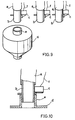
- the second conventional example may incur a problematic point that although the afore-mentioned problem in the first example can be solved, in addition to the requirement that the switches c and the lead wires c whose quantity is equal to the number of connection tubes b , i.e. the actual number of pipes a are needed, an increase in the actual number of lead wires f , made proportionally to an increase in the actual number of tubes a , complicates a wiring of the lead wires f , f ,...as well as makes it unavoidably difficult to fabricate a control panel into which the lead wires f , f ,...are concentrated as small as possible.
- an apparatus for identifying the side of a receiver with respect to the side of injection is known from FR-A-2502134.
- the apparatus as disclosed by this published document comprises a disk secured to the side of the receiver and having a plurality of recesses formed circumferentially thereof, an optional number of the recesses having coded permanent magnets fitted therein, and a disk positioned in the side of injection and having a reader disposed opposite to said permanent magnet circumferentially thereof for detecting and reading identifying codes.
- an electromagnet and an electromagnetic relay in opposition to each other in the position other than said locations on the circumference of the disk. Such arrangements enable the identification of the receiver side.
- the pipe is designed to have a large-diametered disk mounted on the utmost end thereof, whereby said pipe has a larger cross section at the utmost end, thus resulting in the pipe being non-uniformed in diameter. Therefore, the pipe is not easy to handle.
- the present invention is to provide identifying apparatus in use for the transportation of the materials and so on, the apparatus solving all of the afore-mentioned problematic points in the said conventional examples.
- the present invention is in a position to detect an trouble in connecting errorneously the pipe other than the desired one to the receiving part of the piping, for example, in use for the pneumatic force type device for transporting the materials upon completion of connecting the pipe to the receiving part prior to the transportation of the materials.
- the primary object of the present invention is to provide the pipe identifying apparatus, in use, for example, for the pneumatic force type device for transporting the materials, capable of avoiding completely such a problem involved in the errorneous connection of the pipe as stated in the first conventional example.
- Another object of the present invention is to provide the afore-mentioned pipe identifying apparatus in which since the switches and the lead wires, equal in quantity to the actual number of wires as stated in the second conventional example, are not needed, the wiring of the lead wire being performed easily, a piping work and an electrical work at the installation of the pipes can be separately performed so that both the works can be performed individually or at the same time.
- a further object of the present invention is to provide the aforementioned pipe identifying apparatus in which, since the identification of the pipes is coded, even an increase in the actual number of pipes does not cause the number of input processes into a reader and the control panel to be proportionally increased, thereby making the control panel as small as possible.
- a further object of the present invention is to provide a pipe identifying apparatus which is simple in structure wherein troublesome operation may be avoided, unlike FR-A-2502134, and means for preventing any possible drop of the components such as the permanent magnets, positioning means, or alignment means is unnecessary, and which is easy to handle as the pipe to be used is substantially uniform in diameter throughout its entire length.
- a still further object of the present invention is to provide the aforementioned pipe identifying apparatus whose construction makes it possible to change the identifying code optionally to another code so as to enable one pipe to be utilized as a plurality of pipes which have different identifying codes.
- the present invention provides an arrangement in which a plurality of magnetic rings and non-magnetic rings, which form specific identifying codes for each of a plurality of pipes, are heaped up in respective positions in the longitudinal direction of the pipe or a connection instrument removably connected to the pipe, and proximity switches provided on the connection instrument and associating with the magnetic rings to form a magnetic circuit, so that the magnetic circuit is closed to generate electric signals between each proximity switch and each of the plurality of magnetic rings and non-magnetic rings forming the identifying codes, thereby identifying specific connected pipes by means of the generated electric signals.
- the pipe being not optionally limited to ones made of metal, or synthetic resin and the like, may be optional in selecting a tube and a hose without care about its shape, material and size.
- the range of the material passing through the pipe being not particularly limited, includes a transportation of the materials by means of the pneumatic force, a circulation of other medium and the like.
- the reader is a proximity sensor which detects a connecting of the pipes and output on-off signals, and the signals are inputted into a signal processing means.
- the information previously stored in the signal processing means is accommodated to indicate digital or analog signals which are the identifying code of the pipe connected to the side of the receiving part or the name of the materials passing through the pipe on a known display means but also of providing an alarm means (lamp, buzzer and the like) in place of the display means and a comparator (microcomputer and the like) at the same time, whereby, as soon as the identifying code of the pipe connected to the side of the receiving part is detected, the comparator makes a comparison between a desired identifying code which has been set in the comparator in advance and the former identifying code so that if there is no coincidence therebetween, the alarm means allows an alarm to be issued.
- the detection switch being connected to a related control panel (e.g. a control panel for pneumatic force source of the pneumatic force type device for transporting the materials), can be controlled in contact with a controlling of the
- the identifying code is formed by a plurality of the magnetic and non-magnetic rings that can be changed in position so that the identifying code can output various kinds of identifying codes. Furthermore, the identifying code can also be formed by a plurality of magnetic rings which are integrated to the outer circumference of the connection instrument with spaces in between such that the position of the magnetic rings is different from that of other connection instruments, thus causing each identifying code to output different identifying codes from another identifying code, or if the reader adopts photo-electric switches, it may use a through hole. While the identifying code may be provided directly on each of the pipes, such an indirect provision of the identifying code as mounted to a connection tool provided on one end side of each of the pipes is also possible. The identifying code may be optional in being set to each kind and quality of the pipe or material passing through the pipe, being able to be optionally changed to another identifying code of a different design.
- the reader provided on the side of the receiving part detects (discriminates) at once the identifying code inherent in the connected pipe and the display means allows the number of such a pipe to be displayed, thereby enabling a identification of the pipe to be made.
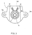
- Figs. 1 to 7 illustrate embodiments of the present invention in which: Fig. 1 is a longitudinal sectional view of a principal part of the first embodiment. Figs. 2-(A) to 2-(H) are outline views illustrating examples of installing the identifying codes. Fig. 3 is a plan view of Fig. 1. Fig. 4 is a longitudinal sectional view of a principal part of the second embodiment. Figs. 5 and 6 are longitudinal sectional views of modified examples of ring articles respectively of Fig. 4. Fig. 7 is an exploded perspective view of a principal part of the third embodiment.
- Fig. 8 is an exploded perspective view of the first conventional example.
- Fig. 9 is an exploded perspective view of the second conventional example.
- Fig. 10 is a longitudinal sectional view of a state of connecting the pipe and the receiving part to each other as illustrated in Fig. 9.
- 1 is the pipe identifying apparatus, which includes a plurality of pipes 2, 2,...having connection instruments 3, 3,...of pipe-shape or other adequate shape fixed to their top ends by means of sleeve-shaped fastening members 3a, 3a,..., identifying codes 10, 10,...being individually provided on the connection instruments 3, 3,..., and the reader 20 for detecting each of the identifying codes 10, 10,...provided on the side of the receiving part 4 of the pipe 2.
- connection instrument 3 has a part 3c of outer diameter smaller than that of a base end side 3b located at its top end side a little distant from its central part, a stage part 3d being interposed between the base end side 3b and the part of smaller outer diameter 3c.
- a cylindrical insertion hole 4a is made in the receiving part 4, which is fixed to be part to be connected 5, such as a hopper and the like, by means of a bolt 5a, and a separation chamber 4b is provided integrally to the lower part of the insertion hole 4a.
- the connection instrument 3 is inserted from the insertion hole 4a to the separation chamber 4b and is fixed to the upper part of a side wall 4c of the receiving part 4 by means of a bolt 6. Loosening of the bolt 6 will enable not only the connection instrument 3 to be removed together with the pipe 2 but also a replacement with other adequate connection instruments 3, 3,...to be performed in a manner of connecting/detaching them.
- 2a is a pipe line and all of 7 and 7a are packings.
- 8 is a mounting cylinder which is not always indispensable.
- a slit S is formed between the mounting cylinder 8 and the connection instrument 3, causing a group of dust and gas and the materials to be transported to be separated from one another: the dust and the gas are adapted to be discharged from an exhaust port 4d to the outside, while the materials to be transported are adapted to drop into the part to be connected 5 which is located under the mounting cylinder 8.
- a limit to such a construction is not always absolute, its design being adequately changeable.
- an adoption of the proximity switch 21 as the reader 20 requires a construction of the identifying code 10 to comprise an optional number (7 units under this embodiment) of ring articles 11 of 2 kinds including magnetic rings 11a, made of such magnetic materials as metal and the like, and non-magnetic rings 11b, made of such non-magnetic materials as synthetic resin and the like.
- the afore-mentioned 7 units of ring articles 11, 11,... are fixedly interposed between the stage part 3d and a snap ring 9.
- a change in the order of 7 units of ring articles 11, 11..., made after removing the snap ring 9, will easily enable the identifying code to be changed.
- the proximity switch 21 detects errorneously the upper-sided or lower-sided ring article 11 other than the ring articles 11, 11,...to which each of the proximity switches 21, 21,...corresponds alternately.
- Figs. 2-(A) to 2-(H) illustrate the identifying code 10 which is ready for being set under the present embodiment. Pulling-out of all the ring articles 11, 11,...from the part under the connection instrument 3 after removing the snap ring 9 will freely rearrange an order of the magnetic ring 11a and the non-magnetic ring 11b, thereby making it possible to set various kinds of identifying codes 10, 10,...
- the identifying code 10 is determined by a repeated permutation between the magnetic rings 11a and the non-magnetic rings 11b, all of which constitute 3 units of the 1st ring article 11, the 3rd one, and the 5th one.
- the identifying code 10 which can be set may be classified into 23 kinds resulting from the permutation being obtained by a selection of 3 positions (each of which is optionally located at any of the 1st ring article 11, the 3rd one, and 5th one with their repeated assortment being allowed) of the magnetic rings 11a and the non-magnetic rings 11b so that if such a selection can be verified into n units of modes, 2 n kinds of identifying codes can be set.
- the signal processing means 25 being not always indispensable, takes a construction in which while it is connected to the detection switches such as the proximity switches 21, 21,..., and receives a signal of the identifying code 10 being detected by the proximity switch 21 and the like, it makes a comparison between the identifying code of the desired pipe, which has been already set in it, and the identifying code 10 of the connected pipe 2 so that if a coincidence takes place therebetween, it displays "OK" mark, but unless so, an alarm means (lamp, buzzer and the like) permits an alarm to be issued.
- the detection switch such as the proximity switch 21 are connected to other control panel, thereby enabling their control to be performed in contact with the related control system.
- the signal processing means 25, being not always limited to the afore-mentioned construction, may optionally take an arrangement of displaying the identifying code 10 simply in figure and character.
- connection instrument 3 Under the present embodiment an rearrangement of the connection instrument 3 will allow code numbers of the pipes to be changed.
- Fig. 4 illustrates the second embodiment.
- the characteristics of this embodiment lie in the points that while the magnetic rings 11a, 11a,...are provided integrally to the outer periphery of the connection instrument 3, annular spaces 12, each of which is formed between the magnetic rings 11a and 11a, are adapted to correspond to the non-magnetic rings 11b, 11b,...of the first embodiment, its other construction being similar to that of the first embodiment.
- the construction of the second embodiment it is not needed to prepare the magnetic ring 11a and the non-magnetic ring 11b, parts other than the connection instrument 3, or any separate parts including the snap ring 9 and the like, the resulting merit is that the actual number of parts is decreased, the productivity being enhanced.
- the number, interval, shape, and permutation of the magnetic ring 11a and the annular space 12 corresponding to the non-magnetic ring 11b may be optional.
- a formed line of the uppermost magnetic ring 11a and the annular space 12 being located next to such a magnetic ring 11a which comprises finally an alternately repetition of such a pair of construction, includes in total 4 units (one of which is used for confirming the connection) of magnetic rings 11a and 3 units of annular spaces 12.
- Such a further possible arrangement as shown in fig. 5 is that an order to read the magnetic ring 11a, the annular ring 12, the magnetic ring 11a with the annular ring 12 being located at the uppermost position being defined, 3 units (one of which is used for confirming the connection) of magnetic rings 11a and 3 units of annular spaces 12 are finally provided.
- a still further possible arrangement is, as shown in Fig.
- Fig. 7 illustrates the third embodiment.
- This embodiment adopts photo-electric switches 22, 22, ...as the reader 20 and a plurality of pairs of light projectors 22a and light receiving units 22b are longitudinally provided opposite to each other with an insertion hole 4a of the receiving part 4 being interposed therebetween.
- a pair or a plurality of pairs of through holes 15 and 15a, opposite to each other and also fitted in said photo-electric switches 22 with the line passage 2a interposed therebetween, are formed in the pipe 2, thereby constructing the identifying code 10.
Landscapes
- Engineering & Computer Science (AREA)
- General Engineering & Computer Science (AREA)
- Mechanical Engineering (AREA)
- Air Transport Of Granular Materials (AREA)
- Geophysics And Detection Of Objects (AREA)
- Rigid Pipes And Flexible Pipes (AREA)
Claims (6)
- Leitungserkennungseinrichtung, umfassend individuelle Erkennungscodes und einen Leser, geeignet zum Lesen der Erkennungscodes, so daß eine Leitung erkannt werden kann, die an die Seite des Aufnahmeteils angeschlossen ist, dadurch gekennzeichnet, daß die Einrichtung umfaßt:
eine Anzahl magnetischer Ringe (11a) undnichtmagnetischer Ringe (11b), wobei die magnetischen Ringe und die nichtmagnetischen Ringe besondere Erkennungscodes (10) für jede Leitung (2) aus einer Anzahl Leitungen (2) bilden und in jeweiligen Stellungen in Längsrichtung auf der Leitung (2) selbst oder auf einem Verbindungsinstrument (3) angeordnet sind, das lösbar mit der Leitung (2) verbunden ist; und
Näherungsschalter (21), die an der Seite des Aufnahmeteils (4) der Leitung (2) selbst oder der Seite des Verbindungsinstruments (3) bereitgestellt und den magnetischen Ringen (11a) zum Bilden eines magnetischen Kreises zugeordnet sind, so daß der magnetische Kreis zwischen jedem Näherungsschalter und jedem Ring aus der Anzahl magnetischer Ringe (11a) und nichtmagnetischer Ringe (11b), die die Erkennungscodes (10) bilden, geschlossen ist, um ein elektrisches Signal zu erzeugen, wobei die besonderen angeschlossenen Leitungen (2) mit Hilfe der erzeugten elektrischen Signale identifiziert werden. - Einrichtung nach Anspruch 1, wobei die Anzahl magnetischer Ringe (11a) und nichtmagnetischer Ringe (11b), die die Erkennungscodes (10) bilden, in ihrer Zusammenstellung wahlweise geändert werden können.
- Errichtung nach Anspruch 1 oder 2, wobei der am obersten Ende angeordnete magnetische Ring (11a) dazu bereitgestellt ist, zu prüfen, ob die Leitung (2) vollständig in das Aufnahmeteil (4) eingesetzt ist.
- Leitungserkennungseinrichtung, umfassend individuelle Erkennungscodes und einen Leser, geeignet zum Lesen der Erkennungscodes, so daß eine Leitung erkannt werden kann, die an die Seite des Aufnahmeteils angeschlossen ist, dadurch gekennzeichnet, daß die Einrichtung umfaßt:
eine Anzahl magnetischer Ringe (11a), umfassend konvexe Teile und ringförmige Freiräume (12) in einer konkaven Anordnung, die nichtmagnetische Bauteile bilden, wobei die magnetischen Ringe und ringförmigen Freiräume besondere Erkennungscodes (10) für jede Leitung aus einer Anzahl Leitungen (2) bilden und in einem Stück mit der Leitung in Längsrichtung ausgebildet sind, entweder auf der Leitung (2) selbst oder auf einem Verbindungsinstrument (3), das lösbar mit der Leitung (2) verbunden ist, und
Näherungsschalter (21), die an der Seite des Aufnahmeteils (4) der Leitung (2) selbst oder der Seite des Verbindungsinstruments (3) bereitgestellt und den magnetischen Ringen (11a) zum Bilden eines magnetischen Kreises zugeordnet sind, so daß der magnetische Kreis zwischen jedem Näherungsschalter und jedem Ring aus der Anzahl magnetischer Ringe (11a) und ringförmiger Freiräume (12), die die Erkennungscodes (10) bilden, geschlossen ist, um ein elektrisches Signal zu erzeugen, wobei die besonderen angeschlossenen Leitungen (2) mit Hilfe der erzeugten elektrischen Signale identifiziert werden. - Einrichtung nach Anspruch 5, wobei der am obersten Ende angeordnete magnetische Ring (11a) dazu bereitgestellt ist, zu prüfen, ob die Leitung (2) vollständig in das Aufnahmeteil (4) eingesetzt ist.
- Leitungserkennungseinrichtung, umfassend individuelle Erkennungscodes und einen Leser, geeignet zum Lesen der Erkennungscodes, so daß eine Leitung erkannt werden kann, die an die Seite des Aufnahmeteils angeschlossen ist, dadurch gekennzeichnet, daß
eine Anzahl photoelektrischer Schalter (22), die Lichtprojektoren (22a) und lichtempfangende Einheiten (22b) enthalten, in Längsrichtung und diametral zum Aufnahmeteil (4) zum Aufnehmen der Leitung (2) angeordnet sind, und daß
ein Paar oder eine Anzahl Paare von Durchgangslöchern (15, 15a) am obersten Ende diametral gegenüberliegend bereitgestellt sind, wobei die Stellungen, in der die photoelektrischen Schalter (22) angeordnet sind, jeweils mit den Durchgangslöchern ausgerichtet sind.
Priority Applications (4)
| Application Number | Priority Date | Filing Date | Title |
|---|---|---|---|
| US07/568,096 US5138139A (en) | 1990-08-15 | 1990-08-14 | Pipe identifying apparatus |
| AT90308953T ATE130280T1 (de) | 1990-08-15 | 1990-08-15 | Rohridentifikationsvorrichtung für pneumatischen transport von puderförmigem oder granuliertem material. |
| DE69023643T DE69023643T2 (de) | 1990-08-15 | 1990-08-15 | Rohridentifikationsvorrichtung für pneumatischen Transport von puderförmigem oder granuliertem Material. |
| EP90308953A EP0471121B1 (de) | 1990-08-15 | 1990-08-15 | Rohridentifikationsvorrichtung für pneumatischen Transport von puderförmigem oder granuliertem Material |
Applications Claiming Priority (1)
| Application Number | Priority Date | Filing Date | Title |
|---|---|---|---|
| EP90308953A EP0471121B1 (de) | 1990-08-15 | 1990-08-15 | Rohridentifikationsvorrichtung für pneumatischen Transport von puderförmigem oder granuliertem Material |
Publications (2)
| Publication Number | Publication Date |
|---|---|
| EP0471121A1 EP0471121A1 (de) | 1992-02-19 |
| EP0471121B1 true EP0471121B1 (de) | 1995-11-15 |
Family
ID=8205525
Family Applications (1)
| Application Number | Title | Priority Date | Filing Date |
|---|---|---|---|
| EP90308953A Expired - Lifetime EP0471121B1 (de) | 1990-08-15 | 1990-08-15 | Rohridentifikationsvorrichtung für pneumatischen Transport von puderförmigem oder granuliertem Material |
Country Status (4)
| Country | Link |
|---|---|
| US (1) | US5138139A (de) |
| EP (1) | EP0471121B1 (de) |
| AT (1) | ATE130280T1 (de) |
| DE (1) | DE69023643T2 (de) |
Families Citing this family (7)
| Publication number | Priority date | Publication date | Assignee | Title |
|---|---|---|---|---|
| DK94792D0 (da) * | 1992-07-23 | 1992-07-23 | Micro Matic As | Koblingsindretning |
| US5390964A (en) * | 1992-10-01 | 1995-02-21 | Gray, Jr.; Lawrence C. | Labeled pipe fitting and method |
| US5474152A (en) * | 1995-04-12 | 1995-12-12 | Teledyne Industries, Inc. | Lubrication system for a starter clutch assembly |
| AUPP584898A0 (en) * | 1998-09-11 | 1998-10-08 | Comweld Group Pty Ltd | A connector |
| FR2871546B1 (fr) * | 2004-06-11 | 2008-02-22 | Hutchinson Sa | Procede de montage d'un capteur dans un circuit hydraulique, et tube rigide dudit circuit equipe d'un tel capteur |
| US9803787B2 (en) * | 2012-09-14 | 2017-10-31 | The United States Of America, As Represented By The Secretary Of The Navy | Magnetically attracted fluid transfer system |
| FR3000169B1 (fr) * | 2012-12-20 | 2015-04-03 | Valeo Sys Controle Moteur Sas | Vanne, notamment vanne de recirculation de gaz d'echappement |
Family Cites Families (6)
| Publication number | Priority date | Publication date | Assignee | Title |
|---|---|---|---|---|
| US3931524A (en) * | 1973-12-21 | 1976-01-06 | Monarch Marking Systems, Inc. | Scanning apparatus |
| FR2502134B1 (fr) * | 1981-03-19 | 1986-03-07 | Lebret Eric | Dispositif de securite, d'antifraude identificateur, transmetteur et recepteur d'informations pour transvasement de fluides ou solides de faibles dimensions stockes et distribues en vrac |
| GB2100705B (en) * | 1981-06-23 | 1985-01-30 | Monitronix Syst | Monitored delivery systems |
| DE3245681C2 (de) * | 1982-01-16 | 1986-02-13 | BKS Sicherheitstechnik GmbH, 5040 Brühl | Nichtmechanisch/mechanisch codierter Schlüssel mit damit zu betätigendem Schließzylinder |
| US4764879A (en) * | 1987-06-25 | 1988-08-16 | The Yellow Springs Instrument Company, Inc. | Fast/accurate calibration for a physical property sensor |
| JPH01294384A (ja) * | 1988-05-20 | 1989-11-28 | Yazaki Corp | コネクタ |
-
1990
- 1990-08-14 US US07/568,096 patent/US5138139A/en not_active Expired - Fee Related
- 1990-08-15 DE DE69023643T patent/DE69023643T2/de not_active Expired - Fee Related
- 1990-08-15 EP EP90308953A patent/EP0471121B1/de not_active Expired - Lifetime
- 1990-08-15 AT AT90308953T patent/ATE130280T1/de active
Also Published As
| Publication number | Publication date |
|---|---|
| ATE130280T1 (de) | 1995-12-15 |
| US5138139A (en) | 1992-08-11 |
| DE69023643T2 (de) | 1996-04-18 |
| DE69023643D1 (de) | 1995-12-21 |
| EP0471121A1 (de) | 1992-02-19 |
Similar Documents
| Publication | Publication Date | Title |
|---|---|---|
| US5138139A (en) | Pipe identifying apparatus | |
| US4338601A (en) | Apparatus for the storage and transfer of information | |
| US10161970B2 (en) | Sequence based mover identification | |
| CA2653585A1 (en) | Radio frequency identification device for plastic container and method of manufacture of same | |
| CN101517517A (zh) | 带有导体片的操作工具 | |
| US20180011509A1 (en) | Remote control | |
| US10982793B2 (en) | Valve control head | |
| US7009525B1 (en) | Multi-angle viewable indicator apparatus | |
| KR970707506A (ko) | 원격 식별 시스템(remote identification system) | |
| US3413447A (en) | Information-bearing label and reading method and apparatus therefor | |
| JP2003505274A (ja) | プリントリボン供給ロール用センサハブ | |
| JP7092334B2 (ja) | エジェクタロッド及びこれを用いた射出成形機 | |
| JPH0754182Y2 (ja) | 配管の識別装置 | |
| US5818226A (en) | Magnetic sensor having a coil with varying turns along the length of a bobbin | |
| JPH0341208B2 (de) | ||
| DE69424267D1 (de) | Fülleinrichtung für Gefässe zum Aufbewahren von Fluiden, insbesondere Gasflaschen, bestehend aus einem Karussel mit Waagen versehen | |
| CN107504018A (zh) | 阀组件 | |
| US5383284A (en) | Measuring carriage for a linear measuring system | |
| JPS58158230A (ja) | 射出成形機用金型 | |
| KR0130922Y1 (ko) | 관종선별 센서 반사경이 부착된 파레트 | |
| US4716400A (en) | Key sensing system | |
| EP0311829B1 (de) | Verfahren und Anordnung zur Markierung und Identifizierung von Textilspulen | |
| JPH11242774A (ja) | 宿泊室における販売装置用の物品識別システム | |
| KR102557114B1 (ko) | 조형물 보강 지지대 | |
| KR102398202B1 (ko) | 범용 근거리 물체감지장치 |
Legal Events
| Date | Code | Title | Description |
|---|---|---|---|
| PUAI | Public reference made under article 153(3) epc to a published international application that has entered the european phase |
Free format text: ORIGINAL CODE: 0009012 |
|
| AK | Designated contracting states |
Kind code of ref document: A1 Designated state(s): AT CH DE FR GB IT LI |
|
| 17P | Request for examination filed |
Effective date: 19920810 |
|
| 17Q | First examination report despatched |
Effective date: 19930803 |
|
| RAP1 | Party data changed (applicant data changed or rights of an application transferred) |
Owner name: MATSUI MANUFACTURING CO., LTD. |
|
| GRAA | (expected) grant |
Free format text: ORIGINAL CODE: 0009210 |
|
| ITF | It: translation for a ep patent filed | ||
| AK | Designated contracting states |
Kind code of ref document: B1 Designated state(s): AT CH DE FR GB IT LI |
|
| REF | Corresponds to: |
Ref document number: 130280 Country of ref document: AT Date of ref document: 19951215 Kind code of ref document: T |
|
| REF | Corresponds to: |
Ref document number: 69023643 Country of ref document: DE Date of ref document: 19951221 |
|
| REG | Reference to a national code |
Ref country code: CH Ref legal event code: NV Representative=s name: NOVAPAT - CABINET CHEREAU S.A. |
|
| ET | Fr: translation filed | ||
| PLBE | No opposition filed within time limit |
Free format text: ORIGINAL CODE: 0009261 |
|
| STAA | Information on the status of an ep patent application or granted ep patent |
Free format text: STATUS: NO OPPOSITION FILED WITHIN TIME LIMIT |
|
| 26N | No opposition filed | ||
| PGFP | Annual fee paid to national office [announced via postgrant information from national office to epo] |
Ref country code: GB Payment date: 19980814 Year of fee payment: 9 |
|
| PGFP | Annual fee paid to national office [announced via postgrant information from national office to epo] |
Ref country code: FR Payment date: 19980819 Year of fee payment: 9 Ref country code: CH Payment date: 19980819 Year of fee payment: 9 |
|
| PGFP | Annual fee paid to national office [announced via postgrant information from national office to epo] |
Ref country code: DE Payment date: 19980825 Year of fee payment: 9 |
|
| PGFP | Annual fee paid to national office [announced via postgrant information from national office to epo] |
Ref country code: AT Payment date: 19980828 Year of fee payment: 9 |
|
| PG25 | Lapsed in a contracting state [announced via postgrant information from national office to epo] |
Ref country code: GB Free format text: LAPSE BECAUSE OF NON-PAYMENT OF DUE FEES Effective date: 19990815 Ref country code: AT Free format text: LAPSE BECAUSE OF NON-PAYMENT OF DUE FEES Effective date: 19990815 |
|
| PG25 | Lapsed in a contracting state [announced via postgrant information from national office to epo] |
Ref country code: LI Free format text: LAPSE BECAUSE OF NON-PAYMENT OF DUE FEES Effective date: 19990831 Ref country code: CH Free format text: LAPSE BECAUSE OF NON-PAYMENT OF DUE FEES Effective date: 19990831 |
|
| GBPC | Gb: european patent ceased through non-payment of renewal fee |
Effective date: 19990815 |
|
| REG | Reference to a national code |
Ref country code: CH Ref legal event code: PL |
|
| PG25 | Lapsed in a contracting state [announced via postgrant information from national office to epo] |
Ref country code: FR Free format text: LAPSE BECAUSE OF NON-PAYMENT OF DUE FEES Effective date: 20000428 |
|
| PG25 | Lapsed in a contracting state [announced via postgrant information from national office to epo] |
Ref country code: DE Free format text: LAPSE BECAUSE OF NON-PAYMENT OF DUE FEES Effective date: 20000601 |
|
| REG | Reference to a national code |
Ref country code: FR Ref legal event code: ST |
|
| PG25 | Lapsed in a contracting state [announced via postgrant information from national office to epo] |
Ref country code: IT Free format text: LAPSE BECAUSE OF NON-PAYMENT OF DUE FEES;WARNING: LAPSES OF ITALIAN PATENTS WITH EFFECTIVE DATE BEFORE 2007 MAY HAVE OCCURRED AT ANY TIME BEFORE 2007. THE CORRECT EFFECTIVE DATE MAY BE DIFFERENT FROM THE ONE RECORDED. Effective date: 20050815 |