EP0470883A2 - Einrichtung und Verfahren zur Ausbeutung kleiner Offshore-Lagerstätten - Google Patents
Einrichtung und Verfahren zur Ausbeutung kleiner Offshore-Lagerstätten Download PDFInfo
- Publication number
- EP0470883A2 EP0470883A2 EP91402091A EP91402091A EP0470883A2 EP 0470883 A2 EP0470883 A2 EP 0470883A2 EP 91402091 A EP91402091 A EP 91402091A EP 91402091 A EP91402091 A EP 91402091A EP 0470883 A2 EP0470883 A2 EP 0470883A2
- Authority
- EP
- European Patent Office
- Prior art keywords
- floating structure
- exploitation
- transfer
- installation according
- production
- Prior art date
- Legal status (The legal status is an assumption and is not a legal conclusion. Google has not performed a legal analysis and makes no representation as to the accuracy of the status listed.)
- Granted
Links
Images



Classifications
-
- E—FIXED CONSTRUCTIONS
- E02—HYDRAULIC ENGINEERING; FOUNDATIONS; SOIL SHIFTING
- E02B—HYDRAULIC ENGINEERING
- E02B17/00—Artificial islands mounted on piles or like supports, e.g. platforms on raisable legs or offshore constructions; Construction methods therefor
-
- E—FIXED CONSTRUCTIONS
- E21—EARTH OR ROCK DRILLING; MINING
- E21B—EARTH OR ROCK DRILLING; OBTAINING OIL, GAS, WATER, SOLUBLE OR MELTABLE MATERIALS OR A SLURRY OF MINERALS FROM WELLS
- E21B43/00—Methods or apparatus for obtaining oil, gas, water, soluble or meltable materials or a slurry of minerals from wells
- E21B43/01—Methods or apparatus for obtaining oil, gas, water, soluble or meltable materials or a slurry of minerals from wells specially adapted for obtaining from underwater installations
-
- E—FIXED CONSTRUCTIONS
- E21—EARTH OR ROCK DRILLING; MINING
- E21B—EARTH OR ROCK DRILLING; OBTAINING OIL, GAS, WATER, SOLUBLE OR MELTABLE MATERIALS OR A SLURRY OF MINERALS FROM WELLS
- E21B43/00—Methods or apparatus for obtaining oil, gas, water, soluble or meltable materials or a slurry of minerals from wells
- E21B43/01—Methods or apparatus for obtaining oil, gas, water, soluble or meltable materials or a slurry of minerals from wells specially adapted for obtaining from underwater installations
- E21B43/017—Production satellite stations, i.e. underwater installations comprising a plurality of satellite well heads connected to a central station
-
- E—FIXED CONSTRUCTIONS
- E02—HYDRAULIC ENGINEERING; FOUNDATIONS; SOIL SHIFTING
- E02B—HYDRAULIC ENGINEERING
- E02B17/00—Artificial islands mounted on piles or like supports, e.g. platforms on raisable legs or offshore constructions; Construction methods therefor
- E02B2017/0095—Connections of subsea risers, piping or wiring with the offshore structure
Definitions
- the present invention relates to a method and an installation suitable for the exploitation of small oil fields.
- the present invention makes it possible in particular to exploit at low cost hydrocarbon fields hitherto economically inaccessible. This is possible due to the use of a flexible method which uses light and standardized materials, and which involves low investments compared to the structures usually used.
- the invention avoids costly withdrawal operations from already existing platforms when main deposits have become unusable, by reusing these platforms for the exploitation of one or more small deposits located near the latter. .
- the secondary well exploitation area from a main platform is relatively small.
- the number of secondary exploitable wells is also low and economic profitability precarious.
- the aim of the present invention is to propose a new method of exploiting at least one secondary submerged (or offshore) oil deposit remote from a main exploitation platform and not justifying the construction of a platform. conventional form of exploitation, as well as an installation for its implementation.
- the operating method is automatically controlled from the main platform.
- at least one essential function for the implementation of the proposed method is controlled by remote control means.
- the object of the present invention is also to propose an installation the structure of which allows the possible recovery of the elements used, once the operation operation has ended and, on the other hand, which allows rotation of use on all the small deposits making up the oil field or other petroleum fields due to the standardization of its equipment.
- At least one essential function for the exploitation of the deposit is controlled by a submerged material transmission link connecting the main platform and the floating structure.
- the hardware link can be multifunction ensuring the supply of electrical energy and the remote control signals necessary for the operation of the various equipment of the floating structure, control installations and means necessary for the operation of the well.
- the floating structure can be immersed between two shallow waters.
- a buoy can be used as a floating structure.
- the floating structure can be fitted with a porous element acting as a shock absorber, or with an anti-heaving device, as described in patent application FR 90 / 15,749.
- the anchoring means are preferably of the funicular or catenary type, more suitable than the taut line anchors in the context of the operating method according to the invention.
- the funicular systems have qualities of reliability and sufficient flexibility. They also offer the advantage of using standard, standardized materials.
- Another advantage which emerges from the use of funicular or catenary type systems is the possibility of recovering the elements which make it possible to anchor the floating structure at the bottom of the sea, which is not possible when using a platform with taut vertical lines, this operation being much heavier to perform.
- the anchor points put in place with the latter are much more complex than those used in catenary type structures which mainly use anchors, and in fact, the anchor elements can be easily recovered.
- This structure therefore allows rotating use of the installation described in the present invention, that is to say the possibility of moving it to different deposits and sites by eliminating or minimizing as much as possible the risks of incompatibility with respect to the different deposits. to exploit.
- the anchoring of the catenary or funicular type is less expensive, more mobile and much less complex than the vertical anchoring with taut lines.
- the anchoring means can, for example, comprise chains, cables or any other means having the qualities required for an anchoring usually used in funicular systems or of catenary type. In all cases, these means will preferably be standardized. In this way, the system can be used "universally" for different types of deposits, at least the deposits located in the same basin.
- One or more pumps can be used as pumping means, each associated with a drive device, at least one of these pumps is a multiphase pump, in particular in the case of petroleum effluents, this pump being associated with a buffer tank intended to regulate the respective flow rates of the gaseous and liquid phases of the effluent.
- An electric motor or a diesel engine with its fuel tank, or a gas turbine with its ancillary equipment can be used as a driving device to use the gas produced by the wells.
- the method makes it possible to transfer the effluents from the floating structure to the main platform over distances preferably between 10 and 80 km.
- the recovery of effluents being easier and faster, it is possible to exploit in an economically profitable way relatively close deposits, between 10 and 30 km for example.
- the method according to the invention making it possible to transfer the effluents from the well to the main platform without separation of their constituents and over great distances, a compound serving to reduce the formation of hydrates or to disperse them can be injected.
- the transfer of all the effluents to the main platform without separation of their phases is advantageous.
- the gas phase can be used to generate energy on the main platform. It can be reinjected into an exhausting deposit to maintain its pressure. It can also be transferred to shore and distributed if the main platform is connected to a distribution network.
- the present invention also relates to an installation or device making it possible to implement the method and to carry out the various operations which make it up.
- the device or installation according to the invention comprises in combination a main operating platform equipped with production means suitable for the exploitation of underwater deposits, at least one system composed of a floating structure and its equipment, anchoring means, connecting the floating structure to the bottom of the sea so that it is in the vicinity of production wells communicating with one of said deposits, first effluent transfer means allowing the transfer of effluents from the deposit to the floating structure, pumping means installed on said floating structure, these means allowing the transfer of petroleum effluents, coming from said deposits without separation between its various constituents or phases, from the floating structure to the main platform, and second transfer means ensuring the transfer of effluents from the floating structure to the main platform.
- the installation comprises at least one submerged material transmission link between the main platform and the floating structure.
- the material link can be submerged between two waters.
- the material link can be placed at the bottom of the water.
- the hardware link can be a multifunction link attached to the production line.
- the anchoring means are preferably of the funicular or catenary type.
- the anchoring means may comprise chains or cables or any other anchoring means having characteristics which allow the anchoring of funicular or catenary type systems.
- the anchoring means may include anchors which have, among other things, the advantage of carrying out the operations of placing and removing with a certain ease.
- the first transfer means include, for example, flexible pipes which can go directly from the floating structure to the bottom of the sea or be supported by an intermediate element, thus giving them an "S" shape which in particular enables them to avoid damage. due to the heaving coming from the swell movements.
- the pumping means may consist of one or more pumps each associated with a drive device, at least one of these pumps being a multiphase pump, this pump being associated with a buffer tank intended to regulate the respective flow rates of the gas phases and liquids.
- the pump drive device can be an electric motor or a diesel engine fitted with its fuel tank or a gas turbine with its associated equipment to use a gas phase produced by the wells.
- the pumping means have sufficient power to allow the transfer of effluents without separation of their constituents from the floating structure to the main platform over a distance preferably between 10 and 80 km.
- the second transfer means may include a pipe connecting the floating structure to the main platform.
- the pipeline can be a flexible or rigid, or partially rigid or flexible pipe resting on the seabed.
- the floating structure may in particular include control means and means necessary for the operation of the well.
- Said floating structure can be provided with equipment allowing the injection of a compound making it possible to reduce the production of hydrates or to disperse them.
- Said floating structure can be equipped with a device making it possible to send scraper tools for cleaning and / or measuring in the second means for transferring the effluents to the main platform.
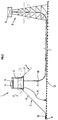
- FIG. 1 shows one of the implementations of the invention for operating a production field comprising several production units 1.
- Anchoring means 2 preferably of catenary or funicular type and comprising for example flexible cables or lines F and anchors A (Fig. 2), keep anchored each production unit 1 above or near the well or wells to bring the deposit into production.
- Each production unit 1 comprises a floating structure 3 such as a buoy, supporting pumping means 4, 5 which are connected to the head of each well by first transfer means 6.
- second transfer means 7 comprising at at least one pipe
- the pumping means 4, 5 convey the effluents from the floating structure to a main platform 8.
- the usual treatment and exploitation equipment equipping the main platform 8 schematically represented in FIG. 2 by the functional block 9.
- the production ascent pipe runs along one of the legs of the platform, FIG. 2 representing it in the center, for reasons of clarity. the figure.
- the distance between the production units and the main platform is arbitrary, but preferably located in the interval 10.80 km.
- the operations control and measurement operations are carried out automatically and provide the platform with an indication allowing the latter to react using remote control means on the equipment located on the floating structure.
- the remote control signals are sent, for example, from the main platform 8 to the floating structure 3 by a hardware link 10.
- the hardware link 10 can be multifunctional and ensure the transfer of the remote control signals as well as the energy necessary for the operation of the various satellite structures.
- a buoy is used whose flotation characteristics are such that part of its body is immersed, the other emerging sufficiently above the surface of the sea 11, so as to install the operating equipment there.
- the buoy can be equipped with a porous element acting as a shock absorber such as that described in application FR 90/15749, this in order to minimize all the heaving movements due in part to the swell.
- the technical data necessary for determining the buoyancy characteristics of the buoy and the pump suitable for the described application can be calculated by known methods.
- buoy a big buoy of the type of those used to moor at sea oil tankers.
- the typical dimensions of the latter in diameter can be between 20 and 30 meters, in height between 5 and 15 meters.
- the anchoring means may advantageously comprise at least one flexible cable or line F and one anchor A or any other available means which make it possible to anchor the production unit 1 securely, such as systems of the catenary or funicular type.
- Line 6 being flexible, it can follow the local drift of the buoy.
- the position of the anchor points 12 and the length of the anchor chains or flexible lines F are determined so that the pipe 6 is always under tension.
- the flexible pipe can optionally be supported by an intermediate element SI (FIG. 1), the latter then taking the form of an S.
- SI intermediate element
- the pumping means 4, 5 located on the floating structure 3 may comprise at least one multiphase pump 4 and its drive device 5 comprising, for example, an electric motor.
- a multiphase pump of the type described in patents FR-2,333,139 and FR2,471,501 is used, equipped with its buffer tank intended to regulate the respective flow rates of the gaseous and liquid phases.
- the position of the buoy at a distance of, for example, between 15 and 80 km from an already existing platform, enables the buoy to be equipped with an electric motor if the main platform has electrical energy, l energy then being supplied by the cable 10.
- the buoy In the case where the platform has no electrical energy, a diesel engine is used, the buoy then comprising a fuel storage means.
- a chemical additive can be injected into line 7 so as to avoid the formation of hydrates or to disperse them.
- This pipe 7 is connected to one end of the production unit 1, the other being attached to the main platform 8.
- the pipe 7 is partially rigid and flexible. It includes, for example, a downward pipe extended by a horizontal section resting on the seabed and ending with a vertical upward pipe, the latter being attached to the main platform 8. The friction of the pipe with the seabed limits its possible drift.
- the pipes can have a J shape.
- the pipe 7 and the cable 10 can be included in the same sheath.
- FIGS. 3A and 3B describe more precisely an anchoring method using anchor lines used in funicular or catenary type systems and an anchor capable of being used.
- the present method offers the advantage of easy installation and lifting and therefore of making the system more mobile than those comprising platforms with taut lines.
- FIG. 3A shows a way of positioning such a type of anchoring line F.
- the tension in the line F is chosen low enough so that the line rests on the seabed over a length L necessary for the anchoring of the anchor in the seabed 13 in the vicinity of the anchor point 12 and so that it thus has a chain configuration.
- An anchor such as that described in patent FR-2,519,310 can be used.
- FIG. 3B describes a possibility for installing an anchor A which comprises at least one plate 21 to which is attached at least one anchoring line F at at least one point by a flexible connection not introducing substantially any moment of rotation at attachment point P.
- the point of application of the tensile force on the plate is fixed and located in front of the barycenter G of the bearing surface of this plate, if we consider the direction of movement of the latter in the seabed during its establishment.
- the process of penetration of the plate into the ground is made easier by combining a sufficient weight for the anchor with members arranged so as to keep the end of the anchor inclined towards the seabed relative to the seabed, or angle i not exceeding 30 °.
- a simple pull on the line is enough for the plate to penetrate the seabed.
- the anchoring is obtained by the progressive insertion of the anchor A which slides in the ground under the effect of the force applied by the chain or taut line F.
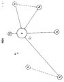
- FIG. 4 represents one of the possible modes of implementation of the method previously described for the exploitation of marginal deposits.
- the operating diagram can be as follows.
- part d of the processing capacity C of the platform becomes unused.
- the processing capacity used on the platform is therefore: C - d.
- the wells P1 to P4 are then put into operation.
- This mode of implementation of the device is only a particular example of the possibilities offered by the device according to the invention for the exploitation of at least one deposit located near a main equipped platform. It is understood that the movements of the satellite buoys from one well to another are made taking into account the length of the pipes and so as to move the pipes already in place as little as possible.
- hoses such as those manufactured by the Coflexip firm makes it easy to adapt the length of the pipe either by cutting or abutting different sections to obtain the necessary length.
- FIG. 5 schematically illustrates a routing and production control system which implements the use of several multiphase pumps.
- four wells are used, the multiphase or effluent fluid to be transferred arriving from the different wellheads, via lines 61, 62, 63, 64.
- the effluent arrival systems from the well to the floating structure are identical for all the wells.
- Line 61 for example, is connected by a safety valve V11 controlled automatically or manually.
- Two remote-controlled valves V21 and V21 ′ allow the effluent to be conveyed either to a COP production collector or to a TOC test collector.
- the safety valves associated with the conduits 62 to 64 are designated by V12, V13 and V14 respectively. Likewise, the following are designated by V22, V22 ′; V23, V23 ′; V24, V24 ′ the valve couples for lines 62 to 64, analogs to the previous V21, V21 ′ couple.
- valves V21, V22, V23, V24 All the effluents are collected, coming from the different wells in the COP production collector, the valves V21, V22, V23, V24 being open, the valves V21 ′, V22 ′, V23 ′, V24 ′ being closed.
- the multiphase fluid regulated by its passage in the buffer tank T is transmitted by a line L2 to a first pumping stage.
- this first pumping stage includes two pumps MP1 and MP1 ′ and the fluid reaches them through lines L3 and L4.
- the first pumping stage can consist of several pumps placed in parallel. Parallel mounting is a special case suitable when the output of the entire production is too large to arrive on a single pump.
- the number of pumping stages and the number of pumps per stage depend on each particular application case, and more precisely on the pressure increase to be carried out, on the mass and volume flow rates of the different phases to be pumped.
- the outputs of the pumps MP1, MP1 ′ of the first stage communicate by valves V31, V31 ′ with a pipe L5, which is connected via a valve V32 with the entry of a second compression stage constituted, by example, of an MP2 pump.
- the output of the latter communicates by a valve V33 with a pipe L6.
- a D1 bypass comprising a VD1 valve, allows the lines L5 and L6 to communicate directly.
- Valves V31 and V31 ′ are fitted with a non-return valve to prevent possible passage of the multiphase fluid from pump MP1 to pump MP1 ′, and from pump MP1 ′, to pump MP1.
- Line L6 communicates via two valves V4 and V5 with line 7 connecting the floating structure to the main platform.
- each pipe 61, 62, 63, 64 coming from the wells is equipped with a safety valve V11, V12, V13, V14 for example an electro-pneumatic valve, which allows their closing in the event of problems. .
- the buffer tank T is equipped with a pressure sensor CP1 and a means for detecting the level of liquid NL1. Depending on the pressure and liquid level values, action is taken by remote control means T1 on the flow rate of the wells, this by a line TP1, which can be an electric or electro-pneumatic line or any other line allowing to transmit the information to the wellhead.
- a line TP1 which can be an electric or electro-pneumatic line or any other line allowing to transmit the information to the wellhead.
- the T1 remote control means also allow lines CM1, CM1 ′ and CM2 to act on the control of the motors M1, M1 ′ and M2, respectively actuating the pumps MP1, MP1 ′ and MP2 for example to control their starting or their stop.
- valve V3 In the event of a deterioration in the operation of one of the pumps, for example the pump MP1, the valve V3 is closed so as to continue to operate the wells in degraded mode with only the pump MP1 ′.
- the CP sensors located after the pumps allow control of the fluid pressure after passage through the pump and therefore provide information on the operation of each of the pumps.
- the method described above also makes it possible to carry out an occasional check of the different characteristics of the fluids coming from the wells, for example, the measurement of the total flow rate of the effluent produced by the well, and of the different phases constituting the effluent.
- valves V21, V22, V23 and V24 are closed, the valves V21 ′, V22 ′, V23 ′ and V24 ′ are opened on the operator's order via lines TV1 and T01.
- the method also makes it possible to inject a compound, such as a chemical additive to avoid the formation of hydrates during a transfer of the effluents or reduce them in their dispersed form in order to facilitate the transfer of the effluent from the satellite to the platform. - main form.
- a compound such as a chemical additive
- Another possibility offered by the method is to allow the cleaning of the pipe 7 by which the fluid is conveyed from the floating structure to the main platform 8, which makes it possible to eliminate any deposit hindering the circulation of the fluid in the pipe. such as paraffins etc.
- a means is used to scrape the pipe through the input E1 of an airlock S, for example, a scraper usually used on production fields, the valve V4 is closed, and the valve is opened. valves V6 and V7. The fluid then pushes the scraper in the pipe 7.
- At least one of the multiphase pumps previously described can be of the helical type.
- This type of pump is particularly well suited for this kind of application.
- the pump can be used over a fairly wide range of variation in the ratio of the quantity of GLR liquid (in English Gas Liquid Ratio), which leads to a reduction in the installations to be placed on the buoy.
- GLR liquid in English Gas Liquid Ratio
- such a pump makes it possible to avoid the separation of the effluent into several phases and therefore, a single pipe is used for the transfer of the constituents between the buoy and the platform.
- the pumping system can call on a simple pump or compressor, and its drive device.
- the drive device can be a diesel engine with its fuel tank, a gas turbine with its ancillary or other equipment.
- petroleum effluent can be sent directly to the platform in the case where the deposit has sufficient natural pressure.
- the method can also be used temporarily to test the production capacities of a still poorly understood deposit.
- a test is carried out using the method described above and the floating structure is replaced, if the test is positive, by an operating device better suited to the capacity of the deposit. It thus avoids investing in a fixed platform and expensive while the production capacities of this deposit are uncertain.
- the floating structure may include a means of injecting chemical additives, serving to protect the pipes from corrosion.
- the floating structure used for the exploitation of the deposit can be equipped with all the means necessary for the exploitation or the well test without modification on the bottom of the proposed system.
- the usual equipment for floating units can be placed there, namely a manifold allowing the production of products from different wells to be grouped together.
- the floating structure may include a basic emergency accommodation and possibly a light bridge for helicopters.
- the present invention avoids the use of amphibious ("submarine" or submerged) pumping means and therefore expensive.
- each floating structure by anchoring means of the funicular type for their ease of use. In some cases, however, stretch lines may be used if the circumstances allow.
Landscapes
- Engineering & Computer Science (AREA)
- Life Sciences & Earth Sciences (AREA)
- Mining & Mineral Resources (AREA)
- Geology (AREA)
- Geochemistry & Mineralogy (AREA)
- General Life Sciences & Earth Sciences (AREA)
- General Engineering & Computer Science (AREA)
- Environmental & Geological Engineering (AREA)
- Fluid Mechanics (AREA)
- Physics & Mathematics (AREA)
- Mechanical Engineering (AREA)
- Civil Engineering (AREA)
- Structural Engineering (AREA)
- Earth Drilling (AREA)
- Production Of Liquid Hydrocarbon Mixture For Refining Petroleum (AREA)
- Cyclones (AREA)
- Drilling And Exploitation, And Mining Machines And Methods (AREA)
- Other Liquid Machine Or Engine Such As Wave Power Use (AREA)
Applications Claiming Priority (4)
| Application Number | Priority Date | Filing Date | Title |
|---|---|---|---|
| FR9010273A FR2665725B1 (fr) | 1990-08-10 | 1990-08-10 | Installation et methode pour l'exploitation en mer de petits gisements. |
| FR9010273 | 1990-08-10 | ||
| FR9104223A FR2674902A1 (fr) | 1991-04-04 | 1991-04-04 | Installation et methode pour l'exploitation en mer de petits gisements petroliers. |
| FR9104223 | 1991-04-04 |
Publications (3)
| Publication Number | Publication Date |
|---|---|
| EP0470883A2 true EP0470883A2 (de) | 1992-02-12 |
| EP0470883A3 EP0470883A3 (en) | 1992-03-25 |
| EP0470883B1 EP0470883B1 (de) | 1995-10-18 |
Family
ID=26228202
Family Applications (1)
| Application Number | Title | Priority Date | Filing Date |
|---|---|---|---|
| EP91402091A Expired - Lifetime EP0470883B1 (de) | 1990-08-10 | 1991-07-25 | Einrichtung und Verfahren zur Ausbeutung kleiner Offshore-Lagerstätten |
Country Status (5)
| Country | Link |
|---|---|
| US (2) | US5226482A (de) |
| EP (1) | EP0470883B1 (de) |
| CA (1) | CA2048888C (de) |
| DK (1) | DK0470883T3 (de) |
| NO (1) | NO302712B1 (de) |
Cited By (2)
| Publication number | Priority date | Publication date | Assignee | Title |
|---|---|---|---|---|
| FR2694785A1 (fr) * | 1992-08-11 | 1994-02-18 | Inst Francais Du Petrole | Méthode et système d'exploitation de gisements pétroliers. |
| WO1996021792A3 (en) * | 1995-01-10 | 1996-10-03 | Mp Seaways Ss Ltd | Riser assembly |
Families Citing this family (29)
| Publication number | Priority date | Publication date | Assignee | Title |
|---|---|---|---|---|
| FR2726859B1 (fr) * | 1994-11-14 | 1997-01-17 | Inst Francais Du Petrole | Methode et systeme de production d'hydrocarbures a partir d'une plate-forme a lignes tendues |
| GB2326655B (en) * | 1997-06-27 | 2001-11-28 | Amerada Hess Ltd | Offshore production of hydrocarbon fluids |
| CA2327098C (en) | 1998-03-30 | 2007-11-06 | Kellogg Brown & Root, Inc. | Extended reach tie-back system |
| FR2780442B1 (fr) * | 1998-06-30 | 2000-07-28 | Inst Francais Du Petrole | Systeme de production polyphasique adapte pour les grandes profondeurs d'eau |
| US6234030B1 (en) | 1998-08-28 | 2001-05-22 | Rosewood Equipment Company | Multiphase metering method for multiphase flow |
| US6164308A (en) * | 1998-08-28 | 2000-12-26 | Butler; Bryan V. | System and method for handling multiphase flow |
| US6230645B1 (en) | 1998-09-03 | 2001-05-15 | Texaco Inc. | Floating offshore structure containing apertures |
| US5983822A (en) | 1998-09-03 | 1999-11-16 | Texaco Inc. | Polygon floating offshore structure |
| US6364021B1 (en) * | 2000-07-11 | 2002-04-02 | Halliburton Energy Services, Inc. | Well management system and method of operation |
| US6782950B2 (en) * | 2000-09-29 | 2004-08-31 | Kellogg Brown & Root, Inc. | Control wellhead buoy |
| US20060000615A1 (en) * | 2001-03-27 | 2006-01-05 | Choi Michael S | Infrastructure-independent deepwater oil field development concept |
| GB2414756B (en) * | 2001-07-12 | 2006-05-10 | Sensor Highway Ltd | Method and apparatus to monitor, control and log subsea wells |
| US20030085036A1 (en) * | 2001-10-11 | 2003-05-08 | Curtis Glen A | Combination well kick off and gas lift booster unit |
| US6742594B2 (en) * | 2002-02-06 | 2004-06-01 | Abb Vetco Gray Inc. | Flowline jumper for subsea well |
| US7178592B2 (en) * | 2002-07-10 | 2007-02-20 | Weatherford/Lamb, Inc. | Closed loop multiphase underbalanced drilling process |
| GB2393981B (en) * | 2002-10-10 | 2006-02-15 | Abb Offshore Systems Ltd | Controlling and/or testing a hydrocarbon production system |
| RU2330154C1 (ru) * | 2004-05-03 | 2008-07-27 | Эксонмобил Апстрим Рисерч Компани , | Система и судно для технического обслуживания шельфовых месторождений |
| US7191836B2 (en) * | 2004-08-02 | 2007-03-20 | Kellogg Brown & Root Llc | Dry tree subsea well communications apparatus and method using variable tension large offset risers |
| US7681672B2 (en) * | 2005-03-31 | 2010-03-23 | The University Of Scranton | Cryogenic pulsejet and method of use |
| RU2393337C1 (ru) * | 2008-10-21 | 2010-06-27 | Тихоокеанский океанологический институт им. В.И. Ильичева Дальневосточного отделения Российской академии наук (ТОИ ДВО РАН) | Способ добычи природного газа в открытом море |
| RU2383717C1 (ru) * | 2008-10-21 | 2010-03-10 | Государственное образовательное учреждение высшего профессионального образования Дальневосточный государственный технический университет (ДВПИ им. В.В. Куйбышева) | Газгольдер |
| RU2382875C1 (ru) * | 2008-10-21 | 2010-02-27 | Государственное образовательное учреждение высшего профессионального образования Дальневосточный государственный технический университет (ДВПИ им. В.В. Куйбышева) | Комплекс для добычи природного газа в открытом море |
| RU2381348C1 (ru) * | 2008-10-21 | 2010-02-10 | Государственное образовательное учреждение высшего профессионального образования Дальневосточный государственный технический университет (ДВПИ им. В.В. Куйбышева) | Способ добычи природного газа в открытом море |
| RU2393338C1 (ru) * | 2008-10-21 | 2010-06-27 | Государственное образовательное учреждение высшего профессионального образования Дальневосточный государственный технический университет (ДВПИ имени В.В. Куйбышева) ГОУ ВПО ДВГТУ | Установка для добычи природного газа в открытом море |
| WO2015048118A2 (en) * | 2013-09-30 | 2015-04-02 | Saudi Arabian Oil Company | Apparatus and method for producing oil and gas using buoyancy effect |
| NO20150922A1 (no) * | 2015-07-15 | 2017-01-16 | Jb Services As | Apparat for å stimulere en petroleumsbrønn og framgangsmåte for å stimulere brønnen |
| NO20150921A1 (no) * | 2015-07-15 | 2017-01-16 | Jb Services As | Apparat for å øke strømningshastigheten til et flerfase fluid og framgangsmåte for å øke strømningshastigheten |
| AU2020386069B2 (en) * | 2019-11-22 | 2025-10-02 | Conocophillips Company | Well stimulation operations |
| DK180938B1 (en) * | 2021-07-09 | 2022-07-04 | Stillstrom As | Mooring buoy |
Family Cites Families (11)
| Publication number | Priority date | Publication date | Assignee | Title |
|---|---|---|---|---|
| US3545215A (en) * | 1968-12-05 | 1970-12-08 | Combustion Eng | Field processing equipment for oil wells mounted at a subsea location |
| FR2333139A1 (fr) * | 1975-11-27 | 1977-06-24 | Inst Francais Du Petrole | Dispositif perfectionne pour le pompage des fluides |
| FR2413536A1 (fr) * | 1977-12-30 | 1979-07-27 | Inst Francais Du Petrole | Poste de mouillage et de transfert pour la production d'hydrocarbures au large des cotes |
| GB1594284A (en) * | 1978-04-28 | 1981-07-30 | Havron Eng Ltd | Control of sub-sea equipment |
| US4339002A (en) * | 1979-08-09 | 1982-07-13 | Halliburton Company | Sea buoy discharge manifold system |
| GB2157749A (en) * | 1983-10-19 | 1985-10-30 | Malcolm Lee | Submersible manifold unit |
| GB8424127D0 (en) * | 1984-09-24 | 1984-10-31 | Havron Ltd | Structures to stand in water |
| US4972907A (en) * | 1985-10-24 | 1990-11-27 | Shell Offshore Inc. | Method of conducting well operations from a moveable floating platform |
| GB2182083B (en) * | 1985-10-24 | 1988-12-14 | Shell Int Research | Method of conducting well operations from an offshore platform |
| GB2191229A (en) * | 1986-03-24 | 1987-12-09 | Subsea Developments Ltd | Offshore hydrocarbon production system |
| FR2621071B1 (fr) * | 1987-09-29 | 1996-01-12 | Inst Francais Du Petrole | Methode et systeme de production d'un effluent contenu dans une formation geologique sous-marine |
-
1991
- 1991-07-25 DK DK91402091.2T patent/DK0470883T3/da active
- 1991-07-25 EP EP91402091A patent/EP0470883B1/de not_active Expired - Lifetime
- 1991-08-09 CA CA002048888A patent/CA2048888C/fr not_active Expired - Fee Related
- 1991-08-09 NO NO913107A patent/NO302712B1/no unknown
- 1991-08-12 US US07/743,762 patent/US5226482A/en not_active Expired - Lifetime
-
1993
- 1993-07-08 US US08/087,411 patent/US5295546A/en not_active Expired - Lifetime
Cited By (3)
| Publication number | Priority date | Publication date | Assignee | Title |
|---|---|---|---|---|
| FR2694785A1 (fr) * | 1992-08-11 | 1994-02-18 | Inst Francais Du Petrole | Méthode et système d'exploitation de gisements pétroliers. |
| US5390743A (en) * | 1992-08-11 | 1995-02-21 | Institut Francais Du Petrole | Installation and method for the offshore exploitation of small fields |
| WO1996021792A3 (en) * | 1995-01-10 | 1996-10-03 | Mp Seaways Ss Ltd | Riser assembly |
Also Published As
| Publication number | Publication date |
|---|---|
| EP0470883B1 (de) | 1995-10-18 |
| CA2048888C (fr) | 1998-08-04 |
| EP0470883A3 (en) | 1992-03-25 |
| NO302712B1 (no) | 1998-04-14 |
| US5226482A (en) | 1993-07-13 |
| NO913107D0 (no) | 1991-08-09 |
| DK0470883T3 (da) | 1995-11-27 |
| US5295546A (en) | 1994-03-22 |
| NO913107L (no) | 1992-02-11 |
| CA2048888A1 (fr) | 1992-02-11 |
Similar Documents
| Publication | Publication Date | Title |
|---|---|---|
| EP0470883B1 (de) | Einrichtung und Verfahren zur Ausbeutung kleiner Offshore-Lagerstätten | |
| EP1073823B1 (de) | Verfahren und vorrichtung zur bildung einer verbindung zwischen meeresgrund und oberfläche mittels einer in grosser tiefe installierten unterwasserleitung | |
| CA2275741C (fr) | Systeme de production polyphasique adapte pour les grandes profondeurs d'eau | |
| EP0097080B1 (de) | System zum Abbau von Lagerstätten unter Wasser | |
| AU2007275960B2 (en) | System and vessel hydrocarbon production and method for intervention on subsea equipment | |
| WO2003093627A1 (fr) | Systeme de colonne montante flexible | |
| WO2003097990A1 (fr) | Systeme de colonne montante reliant deux installations sous-marines fixes a une unite de surface flottante | |
| FR2671046A1 (fr) | Systeme de chargement pour milieux aquatiques. | |
| WO2015107097A1 (fr) | Procede d'installation d'une station de transfert d'energie par pompage dite "marine" et station correspondante | |
| US20160356143A1 (en) | Deepwater production system | |
| WO2010097528A1 (fr) | Installation de liaison fond-surface de type tour hybride multi-riser comprenant des modules de flottabilite coulissants | |
| WO2016110617A1 (fr) | Dispositifs de lestage et/ou de protection pour lignes subaquatiques | |
| FR2710946A1 (fr) | Système de génération et de transfert d'énergie. | |
| EP2652204B1 (de) | Verfahren zur installation einer vorrichtung zur gewinnung von kohlenwasserstoffen | |
| FR2674902A1 (fr) | Installation et methode pour l'exploitation en mer de petits gisements petroliers. | |
| WO2001011183A1 (fr) | Support flottant comportant une cavite centrale comprenant une pluralite de compartiments | |
| FR2665725A1 (fr) | Installation et methode pour l'exploitation en mer de petits gisements. | |
| FR2726859A1 (fr) | Methode et systeme de production d'hydrocarbures a partir d'une plate-forme a lignes tendues | |
| EP2640923B1 (de) | Turm in einem wasserkörper zur erschliessung einer flüssigkeit und zugehöriges installationsverfahren | |
| FR2853618A1 (fr) | Station sous marine autonome | |
| FR2617231A1 (fr) | Methode et appareillage pour executer depuis une installation de surface flottante des operations de forage et des interventions dans un puits subaquatique | |
| FR2984396A1 (fr) | Installation de transfert de fluides entre une tete de puits au fond de l'eau et une structure de surface | |
| EP4540469A1 (de) | System und verfahren zur wassergewinnung aus unterwasser- und/oder küstenfedern mit überlauftank | |
| FR3135998A3 (fr) | Installation pour l’alimentation en eau douce d’un territoire littoral | |
| FR2942643A1 (fr) | Dispositif pour exploiter l'energie de la houle en bordure de mer et la transformer en electricite |
Legal Events
| Date | Code | Title | Description |
|---|---|---|---|
| PUAI | Public reference made under article 153(3) epc to a published international application that has entered the european phase |
Free format text: ORIGINAL CODE: 0009012 |
|
| PUAL | Search report despatched |
Free format text: ORIGINAL CODE: 0009013 |
|
| 17P | Request for examination filed |
Effective date: 19910821 |
|
| AK | Designated contracting states |
Kind code of ref document: A2 Designated state(s): DK FR GB NL |
|
| AK | Designated contracting states |
Kind code of ref document: A3 Designated state(s): DK FR GB NL |
|
| 17Q | First examination report despatched |
Effective date: 19941027 |
|
| GRAA | (expected) grant |
Free format text: ORIGINAL CODE: 0009210 |
|
| AK | Designated contracting states |
Kind code of ref document: B1 Designated state(s): DK FR GB NL |
|
| GBT | Gb: translation of ep patent filed (gb section 77(6)(a)/1977) |
Effective date: 19951024 |
|
| REG | Reference to a national code |
Ref country code: DK Ref legal event code: T3 |
|
| PLBE | No opposition filed within time limit |
Free format text: ORIGINAL CODE: 0009261 |
|
| STAA | Information on the status of an ep patent application or granted ep patent |
Free format text: STATUS: NO OPPOSITION FILED WITHIN TIME LIMIT |
|
| 26N | No opposition filed | ||
| PGFP | Annual fee paid to national office [announced via postgrant information from national office to epo] |
Ref country code: NL Payment date: 20000731 Year of fee payment: 10 |
|
| REG | Reference to a national code |
Ref country code: GB Ref legal event code: IF02 |
|
| PG25 | Lapsed in a contracting state [announced via postgrant information from national office to epo] |
Ref country code: NL Free format text: LAPSE BECAUSE OF NON-PAYMENT OF DUE FEES Effective date: 20020201 |
|
| NLV4 | Nl: lapsed or anulled due to non-payment of the annual fee |
Effective date: 20020201 |
|
| PGFP | Annual fee paid to national office [announced via postgrant information from national office to epo] |
Ref country code: DK Payment date: 20030717 Year of fee payment: 13 |
|
| PG25 | Lapsed in a contracting state [announced via postgrant information from national office to epo] |
Ref country code: DK Free format text: LAPSE BECAUSE OF NON-PAYMENT OF DUE FEES Effective date: 20040802 |
|
| REG | Reference to a national code |
Ref country code: DK Ref legal event code: EBP |
|
| PGFP | Annual fee paid to national office [announced via postgrant information from national office to epo] |
Ref country code: GB Payment date: 20070723 Year of fee payment: 17 |
|
| PGFP | Annual fee paid to national office [announced via postgrant information from national office to epo] |
Ref country code: FR Payment date: 20070716 Year of fee payment: 17 |
|
| GBPC | Gb: european patent ceased through non-payment of renewal fee |
Effective date: 20080725 |
|
| REG | Reference to a national code |
Ref country code: FR Ref legal event code: ST Effective date: 20090331 |
|
| PG25 | Lapsed in a contracting state [announced via postgrant information from national office to epo] |
Ref country code: GB Free format text: LAPSE BECAUSE OF NON-PAYMENT OF DUE FEES Effective date: 20080725 |
|
| PG25 | Lapsed in a contracting state [announced via postgrant information from national office to epo] |
Ref country code: FR Free format text: LAPSE BECAUSE OF NON-PAYMENT OF DUE FEES Effective date: 20080731 |