EP0470807B1 - Optical disc apparatus - Google Patents
Optical disc apparatus Download PDFInfo
- Publication number
- EP0470807B1 EP0470807B1 EP91307202A EP91307202A EP0470807B1 EP 0470807 B1 EP0470807 B1 EP 0470807B1 EP 91307202 A EP91307202 A EP 91307202A EP 91307202 A EP91307202 A EP 91307202A EP 0470807 B1 EP0470807 B1 EP 0470807B1
- Authority
- EP
- European Patent Office
- Prior art keywords
- optical
- optical disc
- light
- waveguide
- optical head
- Prior art date
- Legal status (The legal status is an assumption and is not a legal conclusion. Google has not performed a legal analysis and makes no representation as to the accuracy of the status listed.)
- Expired - Lifetime
Links
- 230000003287 optical effect Effects 0.000 title claims description 539
- 239000000758 substrate Substances 0.000 claims description 89
- 230000004075 alteration Effects 0.000 claims description 48
- 230000001902 propagating effect Effects 0.000 claims description 5
- 230000004044 response Effects 0.000 claims description 5
- 230000004907 flux Effects 0.000 claims description 4
- 238000012937 correction Methods 0.000 claims description 2
- 230000001131 transforming effect Effects 0.000 claims 3
- 238000010897 surface acoustic wave method Methods 0.000 description 48
- 239000004065 semiconductor Substances 0.000 description 43
- 238000010586 diagram Methods 0.000 description 34
- 238000010276 construction Methods 0.000 description 24
- 238000012545 processing Methods 0.000 description 15
- 230000005540 biological transmission Effects 0.000 description 12
- 238000001514 detection method Methods 0.000 description 10
- 230000000694 effects Effects 0.000 description 10
- 238000013461 design Methods 0.000 description 6
- 230000008859 change Effects 0.000 description 4
- 206010073261 Ovarian theca cell tumour Diseases 0.000 description 3
- 238000009826 distribution Methods 0.000 description 3
- 239000000284 extract Substances 0.000 description 3
- 238000000034 method Methods 0.000 description 3
- 230000010355 oscillation Effects 0.000 description 3
- 230000008569 process Effects 0.000 description 3
- 208000001644 thecoma Diseases 0.000 description 3
- 230000002093 peripheral effect Effects 0.000 description 2
- 230000002250 progressing effect Effects 0.000 description 2
- 238000012546 transfer Methods 0.000 description 2
- 206010010071 Coma Diseases 0.000 description 1
- 229910003327 LiNbO3 Inorganic materials 0.000 description 1
- 206010027339 Menstruation irregular Diseases 0.000 description 1
- VYPSYNLAJGMNEJ-UHFFFAOYSA-N Silicium dioxide Chemical compound O=[Si]=O VYPSYNLAJGMNEJ-UHFFFAOYSA-N 0.000 description 1
- XAGFODPZIPBFFR-UHFFFAOYSA-N aluminium Chemical compound [Al] XAGFODPZIPBFFR-UHFFFAOYSA-N 0.000 description 1
- 229910052782 aluminium Inorganic materials 0.000 description 1
- 238000013459 approach Methods 0.000 description 1
- 230000015572 biosynthetic process Effects 0.000 description 1
- 230000007423 decrease Effects 0.000 description 1
- 230000006866 deterioration Effects 0.000 description 1
- 238000009792 diffusion process Methods 0.000 description 1
- 238000010894 electron beam technology Methods 0.000 description 1
- 238000000609 electron-beam lithography Methods 0.000 description 1
- 230000006872 improvement Effects 0.000 description 1
- 230000003993 interaction Effects 0.000 description 1
- 230000005381 magnetic domain Effects 0.000 description 1
- 238000004519 manufacturing process Methods 0.000 description 1
- 239000003973 paint Substances 0.000 description 1
- 229920003023 plastic Polymers 0.000 description 1
- 239000004033 plastic Substances 0.000 description 1
- 230000000644 propagated effect Effects 0.000 description 1
- 230000009467 reduction Effects 0.000 description 1
- 230000005236 sound signal Effects 0.000 description 1
- 239000010409 thin film Substances 0.000 description 1
Images


Classifications
-
- G—PHYSICS
- G11—INFORMATION STORAGE
- G11B—INFORMATION STORAGE BASED ON RELATIVE MOVEMENT BETWEEN RECORD CARRIER AND TRANSDUCER
- G11B7/00—Recording or reproducing by optical means, e.g. recording using a thermal beam of optical radiation by modifying optical properties or the physical structure, reproducing using an optical beam at lower power by sensing optical properties; Record carriers therefor
- G11B7/08—Disposition or mounting of heads or light sources relatively to record carriers
- G11B7/085—Disposition or mounting of heads or light sources relatively to record carriers with provision for moving the light beam into, or out of, its operative position or across tracks, otherwise than during the transducing operation, e.g. for adjustment or preliminary positioning or track change or selection
-
- G—PHYSICS
- G11—INFORMATION STORAGE
- G11B—INFORMATION STORAGE BASED ON RELATIVE MOVEMENT BETWEEN RECORD CARRIER AND TRANSDUCER
- G11B19/00—Driving, starting, stopping record carriers not specifically of filamentary or web form, or of supports therefor; Control thereof; Control of operating function ; Driving both disc and head
- G11B19/02—Control of operating function, e.g. switching from recording to reproducing
- G11B19/12—Control of operating function, e.g. switching from recording to reproducing by sensing distinguishing features of or on records, e.g. diameter end mark
-
- G—PHYSICS
- G11—INFORMATION STORAGE
- G11B—INFORMATION STORAGE BASED ON RELATIVE MOVEMENT BETWEEN RECORD CARRIER AND TRANSDUCER
- G11B23/00—Record carriers not specific to the method of recording or reproducing; Accessories, e.g. containers, specially adapted for co-operation with the recording or reproducing apparatus ; Intermediate mediums; Apparatus or processes specially adapted for their manufacture
- G11B23/02—Containers; Storing means both adapted to cooperate with the recording or reproducing means
- G11B23/03—Containers for flat record carriers
- G11B23/0301—Details
- G11B23/0302—Auxiliary features
-
- G—PHYSICS
- G11—INFORMATION STORAGE
- G11B—INFORMATION STORAGE BASED ON RELATIVE MOVEMENT BETWEEN RECORD CARRIER AND TRANSDUCER
- G11B23/00—Record carriers not specific to the method of recording or reproducing; Accessories, e.g. containers, specially adapted for co-operation with the recording or reproducing apparatus ; Intermediate mediums; Apparatus or processes specially adapted for their manufacture
- G11B23/30—Record carriers not specific to the method of recording or reproducing; Accessories, e.g. containers, specially adapted for co-operation with the recording or reproducing apparatus ; Intermediate mediums; Apparatus or processes specially adapted for their manufacture with provision for auxiliary signals
-
- G—PHYSICS
- G11—INFORMATION STORAGE
- G11B—INFORMATION STORAGE BASED ON RELATIVE MOVEMENT BETWEEN RECORD CARRIER AND TRANSDUCER
- G11B7/00—Recording or reproducing by optical means, e.g. recording using a thermal beam of optical radiation by modifying optical properties or the physical structure, reproducing using an optical beam at lower power by sensing optical properties; Record carriers therefor
- G11B7/002—Recording, reproducing or erasing systems characterised by the shape or form of the carrier
- G11B7/0037—Recording, reproducing or erasing systems characterised by the shape or form of the carrier with discs
-
- G—PHYSICS
- G11—INFORMATION STORAGE
- G11B—INFORMATION STORAGE BASED ON RELATIVE MOVEMENT BETWEEN RECORD CARRIER AND TRANSDUCER
- G11B7/00—Recording or reproducing by optical means, e.g. recording using a thermal beam of optical radiation by modifying optical properties or the physical structure, reproducing using an optical beam at lower power by sensing optical properties; Record carriers therefor
- G11B7/08—Disposition or mounting of heads or light sources relatively to record carriers
- G11B7/085—Disposition or mounting of heads or light sources relatively to record carriers with provision for moving the light beam into, or out of, its operative position or across tracks, otherwise than during the transducing operation, e.g. for adjustment or preliminary positioning or track change or selection
- G11B7/08505—Methods for track change, selection or preliminary positioning by moving the head
-
- G—PHYSICS
- G11—INFORMATION STORAGE
- G11B—INFORMATION STORAGE BASED ON RELATIVE MOVEMENT BETWEEN RECORD CARRIER AND TRANSDUCER
- G11B7/00—Recording or reproducing by optical means, e.g. recording using a thermal beam of optical radiation by modifying optical properties or the physical structure, reproducing using an optical beam at lower power by sensing optical properties; Record carriers therefor
- G11B7/12—Heads, e.g. forming of the optical beam spot or modulation of the optical beam
- G11B7/123—Integrated head arrangements, e.g. with source and detectors mounted on the same substrate
- G11B7/124—Integrated head arrangements, e.g. with source and detectors mounted on the same substrate the integrated head arrangements including waveguides
- G11B7/1245—Integrated head arrangements, e.g. with source and detectors mounted on the same substrate the integrated head arrangements including waveguides the waveguides including means for electro-optical or acousto-optical deflection
-
- G—PHYSICS
- G11—INFORMATION STORAGE
- G11B—INFORMATION STORAGE BASED ON RELATIVE MOVEMENT BETWEEN RECORD CARRIER AND TRANSDUCER
- G11B7/00—Recording or reproducing by optical means, e.g. recording using a thermal beam of optical radiation by modifying optical properties or the physical structure, reproducing using an optical beam at lower power by sensing optical properties; Record carriers therefor
- G11B7/12—Heads, e.g. forming of the optical beam spot or modulation of the optical beam
- G11B7/135—Means for guiding the beam from the source to the record carrier or from the record carrier to the detector
- G11B7/1353—Diffractive elements, e.g. holograms or gratings
-
- G—PHYSICS
- G11—INFORMATION STORAGE
- G11B—INFORMATION STORAGE BASED ON RELATIVE MOVEMENT BETWEEN RECORD CARRIER AND TRANSDUCER
- G11B7/00—Recording or reproducing by optical means, e.g. recording using a thermal beam of optical radiation by modifying optical properties or the physical structure, reproducing using an optical beam at lower power by sensing optical properties; Record carriers therefor
- G11B7/12—Heads, e.g. forming of the optical beam spot or modulation of the optical beam
- G11B7/135—Means for guiding the beam from the source to the record carrier or from the record carrier to the detector
- G11B7/1372—Lenses
- G11B7/1374—Objective lenses
-
- G—PHYSICS
- G11—INFORMATION STORAGE
- G11B—INFORMATION STORAGE BASED ON RELATIVE MOVEMENT BETWEEN RECORD CARRIER AND TRANSDUCER
- G11B7/00—Recording or reproducing by optical means, e.g. recording using a thermal beam of optical radiation by modifying optical properties or the physical structure, reproducing using an optical beam at lower power by sensing optical properties; Record carriers therefor
- G11B7/12—Heads, e.g. forming of the optical beam spot or modulation of the optical beam
- G11B7/135—Means for guiding the beam from the source to the record carrier or from the record carrier to the detector
- G11B7/1372—Lenses
- G11B7/1378—Separate aberration correction lenses; Cylindrical lenses to generate astigmatism; Beam expanders
-
- G—PHYSICS
- G11—INFORMATION STORAGE
- G11B—INFORMATION STORAGE BASED ON RELATIVE MOVEMENT BETWEEN RECORD CARRIER AND TRANSDUCER
- G11B7/00—Recording or reproducing by optical means, e.g. recording using a thermal beam of optical radiation by modifying optical properties or the physical structure, reproducing using an optical beam at lower power by sensing optical properties; Record carriers therefor
- G11B7/12—Heads, e.g. forming of the optical beam spot or modulation of the optical beam
- G11B7/135—Means for guiding the beam from the source to the record carrier or from the record carrier to the detector
- G11B7/1392—Means for controlling the beam wavefront, e.g. for correction of aberration
- G11B7/13925—Means for controlling the beam wavefront, e.g. for correction of aberration active, e.g. controlled by electrical or mechanical means
-
- G—PHYSICS
- G11—INFORMATION STORAGE
- G11B—INFORMATION STORAGE BASED ON RELATIVE MOVEMENT BETWEEN RECORD CARRIER AND TRANSDUCER
- G11B7/00—Recording or reproducing by optical means, e.g. recording using a thermal beam of optical radiation by modifying optical properties or the physical structure, reproducing using an optical beam at lower power by sensing optical properties; Record carriers therefor
- G11B2007/0003—Recording, reproducing or erasing systems characterised by the structure or type of the carrier
- G11B2007/0006—Recording, reproducing or erasing systems characterised by the structure or type of the carrier adapted for scanning different types of carrier, e.g. CD & DVD
Definitions
- the invention relates to an optical disc apparatus which can record, reproduce, or erase information signals onto/from both of an optical disc having a recording density similar to that of a conventional CD (compact disc) and an optical disc having a recording density higher than the above recording density.
- the recording and reproduction of an information signal onto/from an optical disc are executed by converging a beam which is radiated from a semiconductor laser or the like onto a recording layer of the optical disc by a lens.
- the recording layer here denotes a pit layer in the case of a CD and is a layer in which a deformation, a change in optical constant, a formation of a magnetic domain, or the like is performed by a converged laser beam in the case of a recordable optical disc.
- D spot diameter
- the above equation (1) denotes that the beam spot diameter D decreases by using a lens of a large NA. That is, by increasing NA, the high density recording can be executed.
- the above equation (2) denotes that in the case of using a lens of NA which is larger than that of the conventional lens, even if a tilt angle is identical, the coma aberration increases. It will be understood from the equation (2), however, that there is an effect to suppress the coma aberration by setting the thickness d of the disc substrate to be thin. In the optical disc for the high density recording, therefore, it is preferable that the thickness of the disk substrate is thinner than that of the conventional optical disc, so that an optical head using an objective lens corresponding to the thin disc substrate is needed.
- the conventional optical disc of a thick substrate can be also reproduced so that a great amount of conventional software resources can be utilized.
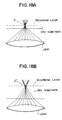
- Figs. 18A and 18B are schematic side elevational views for explaining a situation of the occurrence of the aberration due to the disc substrates having different thicknesses.
- Fig.18A is a diagram in the,case of using-an objective lens which has been designed for a thin disc substrate and shows traces of lights in a state in which a beam has been converged through the disc substrate having the same thickness as the design value.
- a broken line indicates the surface of a recording layer and all of the lights emitted from the objective lens are converged to one point O on the recording layer surface.
- Fig. 18B is a diagram in the case of using an objective lens which has been designed for the same thin disc substrate as that of Fig. 18A and shows traces of lights in a state in which the beam has been converged through the disc substrate having a thickness which is thicker than the design value.
- Fig. 18A is a diagram in the,case of using-an objective lens which has been designed for a thin disc substrate and shows traces of lights in a state in which a beam has been converged through the disc substrate having the same thickness as the design value.
- the lights emitted from the outermost peripheral portion of the objective lens are converged to a point O' on the recording layer surface.
- the light locating near the optical axis is converged at the front side.
- Such a phenomenon is called a spherical aberration.
- the objective lens cannot converge the light beam until what is called a diffraction limit. Therefore, in the case of using the objective lens whose aberration has been corrected for a thin disc substrate, an information signal cannot be recorded, reproduced, or erased onto/from an optical disc having a thick disc substrate. Similarly, in the case of using the objective lens whose aberration has been corrected for a thick disc substrate, an information signal cannot be recorded, reproduced, or erased on to or from an optical disc having a thin disc substrate.
- EP-A-0 452 953 (prior art under Article 54(3) EPC) describes an optical disc recording/reproducing apparatus for use with both a standard optical disc and a two-sided optical disc.
- an optical plate is placed in front of a focusing lens, the optical plate being removed when a standard optical disc is used.
- JP-A-52 153 705 reflecting the preamble of claim 1 describes an optical disc optical disc reproducing apparatus for use with both thin and thick discs.
- the thickness of a disc is detected and a transparent medium is automatically attached or detached between a focusing lens and the disc so as to correct the aberration of the focusing lens.
- EP-A-0 144 436 describes an optical recording and reproducing apparatus which is able to distinguish between an erasable optical disc and a non-erasable optical disc by detecting the presence of absence of a mark in the disc jacket.
- optical disc apparatus which can record, reproduce or erase information signals on to or from a plurality of optical discs in which the thicknesses of the disc substrates are different.
- Embodiments of the invention will be described hereinbelow on the assumption that thicknesses of disc substrates are set to two kinds of thicknesses.
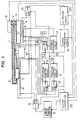
- Fig. 1 is a constructional diagram of an optical disc apparatus in the first embodiment of the invention.
- Fig. 2 is a plan view showing an arrangement of a main section of the embodiment.
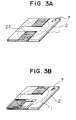
- Figs. 3A and 3B are perspective views of cartridges of optical discs in the embodiment.
- reference numeral 1 denotes a first or second optical disc. Thicknesses of disc substrates of both of the first and second optical discs are different.
- Reference numeral 2 denotes a cartridge which encloses the optical disc 1 and protects. The cartridge 1 is made of plastics or the like.
- Reference numeral 3 denotes a first optical head and 5 indicates a second optical head.
- Each of the optical heads is constructed by a converging optical system comprising: an objective lens; a semiconductor laser; a photo detector; a beam splitter; and the like (all of the above components are not shown).
- Each of the optical head detects an information signal, a focusing error signal, and a tracking error signal which have been recorded on the optical disc 1 on the basis of an intensity or an intensity distribution of the reflected lights of a laser beam irradiated onto the optical disc 1 and generates a photo detection signal to the outside.
- An information signal is recorded onto or erased from the optical disc 1 by modulating an intensity of the laser beam.
- Both of the optical heads have bases to hold the above optical devices and actuators.
- a reproduction information signal, a focusing error signal, and a tracking error signal which are generated from the photo detector of the first optical head 3 are expressed by S 1 , F 1 , and T 1 , respectively.
- Reference numeral 4 denotes a first linear motor which is arranged below the optical disc 1 and moves the first optical head 3 in the radial direction of the disc in parallel with the disc surface.
- Reference numeral 6 denotes a second linear motor which is arranged below the optical disc 1 so as to face the first linear motor 4 and moves the second optical head 5 in a manner similar to the first optical head 3.
- the second linear motor 6 is extended until the further outside of the outermost peripheral portion of the optical disc 1. Therefore, when the second optical head 5 moves to the outermost side, the optical head 5 is projected from the lower surface of the optical disc.
- Reference numeral 7 denotes a discrimination hole formed on the surface of the cartridge 2.
- the cartridge in the embodiment will now be described with reference to Figs. 3A and 3B.
- the discrimination hole 7 is closed in the case where the optical disc 1 enclosed in the cartridge is the first optical disc shown in Fig. 3A and is open in the case where it is the second optical disc shown in Fig. 3B.
- Reference numeral 23 denotes a slide shutter. Since the optical disc apparatus of the embodiment has two optical heads, two slide shutters are provided. When the cartridges are removed from the optical disc apparatus, the slide shutters are closed to protect the internal discs from dusts.
- Reference numeral 8 denotes a light emitting diode (hereinafter, abbreviated to an LED) which is arranged so as to be located over the discrimination hole 7 when the cartridge 2 has been loaded into the optical disc apparatus of the embodiment.
- Reference numeral 9 denotes a photo diode arranged at a position so as to face the LED 8 through the cartridge 2. The photo diode 9 generates a detection signal to a system controller 22, which will be explained hereinlater.
- Reference numeral 10 denotes a first selector for selecting either one of the first group of photo detection signals (S 1 , F 1 , and T 1 ) of the first optical head 3 and the second group of photo detection signals (S 2 , F 2 , and T 2 ) of the second optical head 5 and for outputting the selected signals.
- Reference numeral 11 denotes a tracking control circuit which receives the tracking error signal T 1 or T 2 from among the output signals of the first selector 10 and generates a tracking actuator driving signal to a second selector 12, which will be explained hereinlater.
- reference numeral 12 denotes the second selector to select either an actuator of the first optical head 3 or an actuator of the second optical head 5 as a destination to which the tracking actuator driving signal is supplied.
- Reference numeral 13 denotes a focusing control circuit which receives the focusing error signal F 1 or F 2 from among the signals which are generated from the first selector 10 and generates a focusing actuator driving signal to a third selector 14, which will be explained hereinlater. Further, reference numeral 14 denotes the third selector for selecting either the actuator of the first optical head 3 or the actuator of the second optical head 5 as a destination to which the focusing actuator driving signal is supplied.
- Reference numeral 15 denotes a linear motor control circuit which supplies a driving signal to a fourth selector 16, which will be explained hereinlater, by a control signal which is supplied from the system controller 22, which will be described hereinlater.
- Reference numeral 16 denotes the fourth selector to select either the first linear motor 4 or the second linear motor 6 as an output destination of the driving signal supplied from the linear motor control circuit 15.
- Reference numeral 17 denotes a spindle control circuit which receives the reproduction information signal S 1 or S 2 and generates a control current to a spindle motor 18, which will be explained hereinlater.
- Reference numeral 18 denotes the spindle motor to rotate the optical disc 1.
- Reference numeral 19 denotes a signal processing circuit for executing signal processes such as demodulation and/or decoding or the like to the input signal S 1 or S 2 , for converting into an audio signal or the like, or for outputting the information signal to be recorded onto the optical disc 1 to an LD driving circuit 20, which will be explained hereinlater.
- Reference numeral 20 denotes the LD driving circuit to supply a driving current for allowing laser beams to be emitted from the semiconductor lasers of both of the optical heads to a fifth selector 21, which will be explained hereinlater.
- Reference numeral 21 denotes the fifth selector to switch the output destination of the above driving current to either one of the first and second optical heads 3 and 5 in accordance with a control signal from the system controller 22, which will be explained hereinlater.
- the system controller 22 generates the driving current for allowing the LED 8 to emit the light and receives the detection signal from the photo diode 9 and generates control signals to the first to fifth selectors 10, 12, 14, 16, and 21.
- the system controller 22 also generates control signals to the linear motor control circuit 15 and the signal processing circuit 19.
- switching terminals in the first to fifth selectors 10, 12, 14, 16 and 21 on the first head side are designated by "A" and those on the second head side are designated by "B" in the diagram.
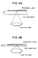
- the first optical disc is a CD or an optical disc having a recording density similar to that of the CD and a thickness of the disc substrate is set to d 1 as shown in Fig. 4A.
- d 1 1.2mm.
- the second optical disc is an optical disc which can execute a recording at a higher density than that of the first optical disc and a thickness of the disc substrate assumes d 2 as shown in Fig. 4B.
- the first optical head 3 has, for instance, a semiconductor laser of a wavelength of 780 nm and an objective lens of an NA of 0.45, so that the laser beam can be converged to a spot diameter ⁇ of about 2.1 ⁇ m.
- an optical design of the objective lens has been made so as to correct the aberration by the disc substrate of the thickness d 1 .
- the second optical head 5 has, for instance, the same semiconductor laser as that of the first optical head and an objective lens of an NA of 0.8, so that the laser beam can be converged until a spot diameter of 1.2 ⁇ m.
- an optical design of the objective lens has been made so as to correct the aberration by the disc substrate of the thickness d 2 .
- the LED 8 emits the light and the photo diode 9 detects the presence or absence of a transmission light which passes through the discrimination hole 7.
- the photo diode 9 detects the transmission light and generates a detection signal to the controller 22.
- the controller 22 determines that the disc in the loaded cartridge 2 is the second optical disc, so that the controller 22 supplies control signals to the first to fifth selectors 10, 12, 14, 16, and 21 so as to select the terminals B on the second optical head side.
- the semiconductor laser of the second optical head 5 is selected as an output destination of the driving current which is supplied from the LD driving circuit 20.
- the photo detector of the second optical head 5 is selected as an input destination of the tracking control circuit 11, focusing control circuit 13, spindle control circuit 17, and signal processing circuit 19.
- the actuator of the second optical head 5 is selected as an output destination of the actuator driving signals of the tracking control circuit 11 and focusing control circuit 13.
- the second linear motor 6 is selected as an output destination of the driving current of the linear motor control circuit 15.
- the second optical head 5 irradiates the laser beam and converges onto an information track on the optical disc 1 without an aberration. Simultaneously, the second optical head 5 detects the reflected lights from the disc and generates the information signal S 2 , focusing error signal F 2 , and tracking error signal T 2 . Those signals are supplied through the first selector 10 to the respective circuits. That is, the signal S 2 is supplied to the spindle control circuit 17 and signal processing circuit 19. The signal F 2 is supplied to the focusing control circuit 13. The signal T 2 is supplied to the tracking control circuit 11. The tracking control circuit 11 produces the tracking actuator driving signal in accordance with the signal T 2 and supplies to the actuator of the second optical head 5 through the second selector 12, thereby eliminating the tracking error.
- the focusing control circuit 13 also produces the focusing actuator driving signal in accordance with the signal F 2 and supplies to the actuator of the second optical head 5 through the third selector 14, thereby eliminating the focusing error.
- the linear motor control circuit 15 generates the driving current to the linear motor 6 in response to the control signal from the system controller 22, thereby moving the second optical head 5 in the inner or outer rim direction of the optical disc 1.
- the spindle control circuit 17 extracts a clock component from the information signal S 2 and controls the spindle motor 18, thereby rotating the optical disc 1 at a constant linear velocity (CLV) or a constant angular velocity (CAV) or the like.
- the signal processing circuit 19 executes signal processes such as demodulation, decoding, and the like to the information signal S 2 in the reproducing mode and generates to the outside as audio or video signals or the like. On the other hand, the signal processing circuit 19 executes signal processes such as encoding, modulation, and the like to the audio or video signals or the like which have been supplied from the outside in the recording mode and generates to the LD driving circuit 20 as a recording signal. Until the cartridge 2 is loaded, the second optical head 5 records or reproduces the information signal onto/from the second optical disc 1.
- the system controller 22 determines that the disc in the cartridge 2 is the foregoing first optical disc.
- the controller 22 generates control signals to the first to fifth selectors 10, 12, 14, 16, and 21 so as to select the terminals A on the first optical head side. Therefore, the semiconductor laser of the first optical head 3 is selected as an output destination of the driving current which is supplied from the LD driving circuit 20.
- the photo detector of the first optical head 3 is selected as an input destination of the tracking control circuit 11, focusing control circuit 13, spindle control circuit 17, and signal processing circuit 19.
- the actuator of the first optical head 3 is selected as an output destination of the actuator driving signals of the tracking control circuit 11 and focusing control circuit 13.
- the first linear motor 4 is selected as an output destination of the driving current of the linear motor control circuit 17. Therefore, the first optical head 3 irradiates the laser beam and converges onto the information track on the optical disc 1 without an aberration. Simultaneously, the reflected lights from the disc are detected and generated as the information signal S 1 , focusing error signal F 1 , and tracking error signal T 1 .
- the above signals are supplied through the first selectors 10 to the respective circuits. That is, the signal S 1 is supplied to the spindle control circuit 17 and signal processing circuit 19. The signal F 1 is supplied to the focusing control circuit 13. The signal T 1 is supplied to the tracking error detecting circuit 11.
- the subsequent operations are similar to those in the case of the second optical disc mentioned above.
- the controller 22 controls the second linear motor 6, thereby moving the second optical head 5 to the outside of the disc surface as shown in Fig. 2. Due to this, it is possible to prevent that the objective lens of the second optical head 5 collides with the optical disc 1 due to a surface oscillation.
- the signal can be preferably recorded, reproduced, or erased by the optical head suitable for the thickness of each disc substrate.
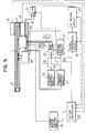
- Fig. 5 shows a constructional diagram of an optical disc apparatus according to the second embodiment of the invention.
- the second embodiment differs from the foregoing first embodiment with respect to a point that a third optical head 30 is arranged in place of the first and second optical heads 3 and 5 and a point that the second, third, and fourth selectors 12, 14, and 16 are omitted. That is, the tracking actuator driving current which is generated from the tracking control circuit 11 and the focusing actuator driving current which is generated from the focusing control circuit 13 are directly supplied to the third optical head 30.
- the driving current which is generated from the linear motor control circuit 15 is directly supplied to the first linear motor 4.
- Fig. 6 shows a detailed constructional diagram of the third optical head 30 in the second embodiment of the invention.
- reference numeral 1 denotes the first or second optical disc; 32 a first semiconductor laser as a light source; 33 a first collimating lens for converting a laser beam from the first semiconductor laser 32 into a parallel beam; 34 first beam splitter to divide the beam into two beams; 35 a first mirror to change the direction of the beam; 36 a first objective lens to converge the beam onto the optical disc 1; 37 a first detecting lens to converge the reflected lights which have been divided by the beam splitter 34; and 38 a first photo detector to obtain an information reproduction signal, a focusing error signal, and a tracking error signal from the converged reflected lights.
- the above components 32 to 38 construct a first converging optical system 31.
- Reference numeral 39 denotes a lens holder to hold the first objective lens 36 and a second objective lens 46, which will be explained hereinlater.
- Reference numeral 40 denotes an actuator to support the lens holder 39. The driving currents are supplied from the tracking control circuit 11 and focusing control circuit 13 to the actuator 40.
- Reference numeral 42 denotes a second semiconductor laser as a light source; 43 a second collimating lens to convert a laser beam from the second semiconductor laser 42 into a parallel beam; 44 a second beam splitter to divide the beam into two beams; 45 a second mirror to change the direction of the beam; 46 the second objective lens to converge the beam onto the optical disc 1; 47 a second detecting lens to converge the reflected lights which have been divided by the second beam splitter 44; and 48 a second photo detector to obtain the information reproduction signal, focusing error signal, and tracking error signal from the converged reflected lights.
- the above components 42 to 48 construct a second converging optical system 41.
- the above first converging optical system 31, the second converging optical system 41, and the actuator 40 are mounted on a same base member (not shown) and construct the third optical head 30.
- the base member is ordinarily made of aluminum or the like and is attached to the first linear motor 4.
- the system controller 22 determines that the disc in the loaded cartridge 2 is the second optical disc, so that the controller 22 selects the second converging optical system 41 of the third optical head 30. That is, the system controller 22 generates control signals to the first and fifth selectors 10 and 21 so as to make the second semiconductor laser 42 and the second photo detector 48 operative.
- the laser beam emitted from the second semiconductor laser 42 is converted into the parallel beam by the second collimating lens 43.
- the parallel beam is converged onto the second optical disc 1 by the second objective lens 46 through the second beam splitter 44 and the second mirror 45.
- the laser beam reflected by the disc is again converted into the parallel beam by the second objective lens 46 and is separated from the optical axis by the second beam splitter 44 through the second mirror 45 and is converged onto the second photo detector 48 by the second detecting lens 47.
- the second photo detector 48 produces the information signal, focusing error signal, and tracking error signal from the converged reflected light from the disc and supplies to the first selector 10.
- the actuator 40 finely moves the lens holder 39 in the tracking and focusing directions by the driving currents from the tracking control circuit 11 and the focusing control circuit 13, thereby accurately converging the laser beam onto an information track on the optical disc 1.
- first linear motor 4 Since the operations of the first linear motor 4, first selector 10, tracking control circuit 11, focusing control circuit 13, linear motor control circuit 15, spindle control circuit 17, spindle motor 18, signal processing circuit 19, LD driving circuit 20, fifth selector 21, and system controller 22 are substantially the same as the optical disc apparatus of the first embodiment mentioned above, their descriptions are omitted here.
- the system controller 22 decides that the disc in the loaded cartridge 2 is the first optical disc mentioned above, so that the controller 22 selects the first converging optical system 31 of the third optical head 30. That is, the system controller 22 generates control signals to the first and fifth selectors 10 and 21 so as to make the first semiconductor laser 32 and the first photo detector 38 operative.
- the operation of the first converging optical system 31 is substantially the same as that of the second converging optical system 41 mentioned above. Until the cartridge 2 is unloaded, the recording, reproduction, or erasure of the information signal onto/from the first optical disc is executed by the first converging optical system 31.
- the linear motor can be commonly used as a single part and the number of parts can be reduced.
- Fig. 7 shows a constructional diagram of an optical disc apparatus according to the third embodiment of the invention.
- the third embodiment differs from the second embodiment with respect to a point that a fourth optical head 50 is arranged in place of the third optical head 30 and a point that the first selector 10 and the fifth selector 21 are omitted. That is, the photo detection signal which is generated from the fourth optical head 50 is directly supplied to the tracking control circuit 11, focusing control circuit 13, spindle control circuit 17, and signal processing circuit 19. The driving current which is generated from the LD driving circuit 20 is directly supplied to the fourth optical head 50.
- Fig. 8 shows a detailed constructional diagram of the fourth optical head 50 in the third embodiment of the invention.
- reference numeral 1 denotes the first or second optical disc; 32 the first semiconductor laser as a light source; 33 the first collimating lens to convert the laser beam from the first semiconductor laser 32 into the parallel beam; 34 the first beam splitter to divide the laser beam into two beams; and 35 the first mirror to change the direction of the beam.
- the first objective lens 36 and the second objective lens 46 are the same as those mentioned in the second embodiment of the invention.
- the first objective lens 36 is arranged between the first mirror 35 and the optical disc 1.
- the second objective lens 46 is arranged between the first beam splitter 34 and the optical disc 1.
- the aberration of the first objective lens 36 has been corrected in correspondence to the first optical disc having the disc substrate of the thickness d 1 .
- the aberration of the second objective lens 46 has been corrected in correspondence to the second optical disc having the disc substrate of the thickness d 2 .
- Reference numeral 51 denotes a first shutter arranged between the first objective lens 36 and the first mirror 35 and on the optical path which passes through the first objective lens 36.
- Reference numeral 52 denotes a second shutter which is arranged between the second objective lens 46 and the first beam splitter 34 and on the optical path which passes through the second objective lens 46.
- the first and second shutters 51 and 52 open or close the optical paths by control signals from the system controller 22, respectively.
- Reference numeral 37 denotes the first detecting lens to converge the reflected lights which have been divided by the beam splitter 34.
- Reference numeral 38 denotes the first photo detector to obtain the information reproduction signal, focusing error signal, and tracking error signal from the converged reflected light.
- the first objective lens 36 constructs the first converging optical system mentioned in the second embodiment of the invention together with the first semiconductor laser 32, the first collimating lens 33, the first beam splitter 34, and the first mirror 35.
- the second objective lens 46 constructs the second converging optical system together with the first semiconductor laser 32, the first collimating lens 33, the first beam splitter 34, and the first mirror 35 which are commonly used for the first converging optical system.
- the first converging optical system is mounted onto a common base (not shown) together with the first and second shutters 51 and 52, thereby constructing the fourth optical head 50. Since the lens holder 39 and the actuator 40 have the same construction as those in the third optical head 30 in the second embodiment, their descriptions are omitted here.
- the fourth optical head 50 is attached to the first linear motor 4.
- the controller 22 determines that the disc in the loaded cartridge 2 is the second optical disc
- the controller 22 generates control signals to the first and second shutters 51 and 52 of the fourth optical head 50.
- the first shutter 51 is closed and the second shutter 52 is open.
- the laser beam emitted from the first semiconductor laser 32 is converted into the parallel beam by the first collimating lens 33 and is divided into the transmission light and the reflected light by the first beam splitter 34.
- the transmission light is shut out by the first shutter 51 via the first mirror 35.
- the second shutter 52 only the reflected light passes through the second shutter 52 and is converged onto the optical disc 1 by the second objective lens 46.
- the light reflected by the optical disc 1 is again converted into the parallel light by the second objective lens 46 and passes through the second shutter 52 and is reflected and separated by the first beam splitter 34 and is converged onto the first photo detector 38 by the first detecting lens 37.
- the first photo detector 38 generates the focusing error signal and tracking error signal from the converged reflected light of the disc and reproduces the information signal on the disc. The above operations are executed until the cartridge 2 is unloaded.
- the system controller 22 determines that the disc in the loaded cartridge 2 is the first optical disc, the first shutter 51 is opened and the second shutter 52 is closed. In the above state, in the transmission light and the reflected light by the first beam splitter 34, the reflected light is shut out by the second shutter 52 and only the transmission light passes through the first shutter 51 and is converged onto the optical disc 1 by the first objective lens 36.
- the other operations are executed in a manner similar to those in the case of the second optical disc.
- the semiconductor laser, collimating lens, beam splitter, detecting lens, and photo detector in each of the converging optical system can be commonly used and the size and weight of the optical head can be reduced. Therefore, assuming that a driving force of the linear motor is the same, the improvement of the performance such as reduction of the seeking time and the like can be realized.
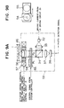
- Figs. 9A and 9B show a detailed constructional diagram of an optical head of an optical disc apparatus in the fourth embodiment of the invention.
- first semiconductor laser 32, first collimating lens 33, first beam splitter 34, second objective lens 46, first detecting lens 37, and first photo detector 38 are constructed in a manner similar to those in the foregoing fourth optical head 50, their descriptions are omitted here.
- Reference numeral 56 denotes a lens holder to hold the second objective lens 46; 57 an actuator to which the lens holder 56 is attached; 54 a wave front correcting lens attached to a slider 55, which will be explained hereinlater, so that the optical axis is in parallel with the optical axis of the second objective lens 46; and 55 the slider which supports the wave front correcting lens 54 and is arranged so as to transverse in the plane which is perpendicular to the light flux between the first beam splitter 34 and the second objective lens 46, thereby enabling the wave front correcting lens 54 to be moved in such a plane.
- Such a movable range is set to a position (shown by P 1 in the diagram) where the wave front correcting lens 54 is perfectly deviated out of the light flux or a position (shown by P 2 in the diagram) where the optical axis of the slider 55 coincides with the optical axis of the second objective lens 46.
- the above-mentioned component elements are attached to a base (not shown) and construct a fifth optical head 53.
- Fig. 9B is a plan view when the wave front correcting lens 54 and the slider 55 are seen from the direction of the optical axis.
- the lens 54 is movable in the directions shown by arrows.
- the wave front correcting lens 54 has been designed in a manner such that a synthetic optical system with the second objective lens 46 is identical to the foregoing first objective lens. That is, the lens 54 has been designed so as to correct the aberration by the disc substrate of the first optical disc.
- the second objective lens 46 constructs the second converging optical system mentioned in the second embodiment of the invention together with the first semiconductor laser 32, first collimating lens 33, and first beam splitter 34 and can be also regarded such that they construct the first converging optical system by adding the wave front correcting lens 54 to the second converging optical system.
- the operation of the optical disc apparatus in the fourth embodiment with the above construction will now be described hereinbelow with respect to only the fifth optical head 53.
- the kind of optical disc is detected in a manner similar to the above. If the system controller 22 determines that the disc in the loaded cartridge 2 is the second optical disc, the controller 22 generates a control signal to the slider 55. When the control signal is supplied, the slider 55 moves the wave front correcting lens 54 to the position P 1 .
- the laser beam emitted from the first semiconductor laser 32 is converted into the parallel light by the first collimating lens 33 and is reflected by the first beam splitter 34 and is converged onto the optical disc 1 by the second objective lens 46.
- the light reflected by the optical disc 1 is again converted into the parallel light by the second objective lens 46.
- the parallel light passes through the first beam splitter 34 and is converged onto the first photo detector 38 by the first detecting lens 37.
- the first photo detector 38 generates a photo detection signal in a manner similar to the above. The above operations are executed until the optical disc 1 is unloaded.
- the slider 55 moves the wave front correcting lens 54 to the position P 2 .
- the laser beam emitted from the first semiconductor laser 32 passes through the wave front correcting lens 54 and the second objective lens 46 and is converged onto an information track on the optical disc 1 without an aberration.
- the operations similar to those in the case of the second optical disc are executed.
- the wave front correcting lens 54 serving as an aberration correcting means is held by the slider 55 and is movably arranged, the objective lens can be commonly used and a total mass which must be moved by the actuator 57 can be reduced. Thus, a burden to the driving force of the actuator can be reduced and a low electric power consumption can be accomplished.
- the optical head 50 in the fourth embodiment has the second objective lens 46 corresponding to the optical disc having the disc substrate of the thickness d 2 and, further, corrects the aberration to the optical disc having the disc substrate of the thickness d 1 by the wave front correcting lens 54.
- an opposite construction can be also used. Namely, the above effect is also derived by a construction such that the first objective lens 36 corresponding to the optical disc of the disc substrate of the thickness d 1 is used in place of the second objective lens 46 and a wave front correcting lens which has been designed so as to correct the aberration due to the disc substrate of the thickness d 2 is provided.
- the invention can be also applied to the case of three or more kinds of thicknesses of the disc substrates.
- the number of optical elements such as objective lenses and the like is increased in accordance with the number of kinds of thicknesses of the disc substrates.
- the discriminating means of the optical disc three or more kinds of optical discs can be discriminated by, for instance, checking a plurality of discrimination holes which are formed in the cartridge. For example, by forming n discriminating holes, 2 n kinds of optical discs can be discriminated.
- the discrimination hole 7 formed on the cartridge 2, the LED 8, and the photo diode 9 have been used as disc discriminating means, paints of different reflectances can be also coated onto the surface of the cartridge 2 in place of the discrimination hole or a mechanical switch or the like can be also used in place of the LED and the photo diode.
- a difference between thicknesses of the disc substrates can be also directly discriminated by a reflected laser beam from the discs without using the cartridge.
- a tracking error signal cannot be ordinarily obtained from an optical disc of a thick disc substrate due to a spherical aberration of the converging beam. Consequently, two optical discs having different thicknesses can be discriminated by checking the presence or absence of the tracking error signal. In such a case, there is an excellent effect such that the apparatus is simplified because there is no need to use the detecting means such as LED and photo diode and the like.
- optical head in each of the above-described optical disc apparatuses has been constructed by a conventional optical system using the objective lens made of a quartz glass or the like.
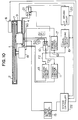
- Fig. 10 is a block diagram showing a construction of an optical disc apparatus according to the fifth embodiment of the invention.
- Fig. 11 is a schematic perspective view showing a construction of an optical head of the optical disc apparatus in the fifth embodiment of the invention. Since a construction shown in Fig. 10 is substantially the same as that of the optical disc apparatus in the second embodiment of the invention shown in Fig. 5 except that a sixth optical head 60 is used, its description is omitted here. The sixth optical head 60 shown in Fig. 11 will now be described in detail hereinbelow.
- reference numeral 1 denotes the same optical disc as that described in the foregoing embodiments.
- Reference numeral 200 denotes an information track formed on the optical disc 1.
- Reference numeral 61 denotes a substrate formed by LiNbO 3 or the like. The substrate 61 is attached to a head base through a focusing actuator and a tracking actuator and constructs the sixth optical head 60 together with them. Since the focusing actuator, tracking actuator, and head base which have conventionally been well known can be used as those components, their detailed description and the drawings are omitted here.
- Reference numeral 62 denotes an optical waveguide formed on the substrate 51 by Ti diffusion or the like; 63 a first semiconductor laser coupled to an edge surface of the optical waveguide 62; and 64 a first waveguide lens arranged on an optical path of the waveguide light which has been emitted from the first semiconductor laser 63 and entered the optical waveguide 62.
- a Fresnel lens formed by an electron beam lithography can be used as a lens 64.
- Reference numeral 65 denotes a first converging grating coupler formed on the optical path of the parallel waveguide light. The coupler 65 emits the waveguide light to a position out of the optical waveguide 62 and converges onto the optical disc 1.
- the first converging grating coupler 65 is a grating having a chirp (irregular period) by a curve formed on the waveguide by electron beam direct drawing or the like.
- Reference numeral 66 denotes a first beam splitter which is arranged between the first waveguide lens 64 and the first converging grating coupler 65 and separates the waveguide light which has been returned into the optical waveguide 62 through the first converging grating coupler 65 after it had been reflected by the optical disc 1.
- Reference numeral 67 denotes a first waveguide converging lens which is arranged on the optical path of the return waveguide light which has been separated by the first beam splitter 66 and converges the return light.
- Reference numeral 68 denotes a first photo detector which is coupled to the side surface of the optical waveguide 62 and detects the return waveguide light which has been converged by the first waveguide converging lens 67.
- reference numeral 69 denotes a second semiconductor laser coupled to the edge surface of the optical waveguide 62; 70 a second waveguide lens arranged on the optical path of the waveguide light which has been emitted from the second semiconductor laser 69 and entered the optical waveguide 62; and 71 a second converging grating coupler formed on the optical path of the parallel waveguide light.
- the coupler 71 emits the waveguide light to a position out of the optical waveguide 62 and converges onto the optical disc 1.
- Reference numeral 72 denotes a second beam splitter which is arranged between the second waveguide lens 70 and the second converging grating coupler 71 and separates the waveguide light which has been returned into the optical waveguide 62 through the second converging grating coupler 71 after it had been reflected by the optical disc 1.
- Reference numeral 73 denotes a second waveguide converging lens which is arranged on the optical path of the return waveguide light which has been separated by the second beam splitter 72 and converges the return waveguide light.
- Reference numeral 74 denotes a second photo detector which is coupled to the side surface of the optical waveguide 62 and detects the return waveguide light converged by the second waveguide converging lens 73.
- the first and second beam splitters 66 and 72 are attached at positions which are deviated so that the reflected light of each beam splitter does not enter the other beam splitter as a stray light.
- optical waveguide and a waveguide type device have been described in detail in, for example, Nishihara, Haruna, and Saihara, "Optical Integrated Circuit", Ohm Co., Ltd., 1985, or the like.
- both of the above well-known optical waveguide and waveguide type device can be used in the optical waveguide 62 or the like.
- the driving current is supplied to the first semiconductor laser 63.
- the laser 63 emits a laser beam from one edge surface of the optical waveguide 62.
- the laser beam propagates as a waveguide light.
- the waveguide light is converted into the parallel light by the first waveguide lens 64.
- the parallel light transmits the first beam splitter 66 and subsequently enters the first converging grating coupler 65.
- the coupler 65 extracts the parallel light out of the optical waveguide 62 and converges onto the information track 200 on the first optical disc 1.
- the reflected light from the disc surface again enters the optical waveguide 62 through the first converging grating coupler 65 and propagates as a return waveguide light in the opposite direction.
- the return waveguide light is reflected in the direction of the first waveguide converging lens 67 in the first beam splitter 66.
- the lens 67 converges the return waveguide light onto the first photo detector 68.
- the first photo detector 68 detects the information signal and the servo signals such as focusing error signal, tracking error signal, and the like which have been recorded on the first optical disc 1 on the basis of an intensity and an intensity distribution of the return waveguide light and generates to the outside.
- the sixth optical head 60 By modulating the driving current which is supplied to the first semiconductor laser 63, the sixth optical head 60 emits the intensity modulated laser beam, thereby recording or erasing the information signal onto/from the first optical disc 1.
- the optical disc 1 is the second optical disc
- the operations similar to those in the case of the foregoing first optical disc are executed by the second semiconductor laser 69, second waveguide lens 70, second converging grating coupler 71, second beam splitter 72, second waveguide converging lens 73, and second photo detector 74.
- the substrate 61 is supported from the head base by a focusing actuator and a tracking actuator.
- the position of the substrate 61 itself is controlled by the foregoing servo signals so that the laser beam is accurately irradiated onto the information track 200 on the disc.
- the first converging grating coupler 65 which is formed on the optical waveguide 62 and corresponds to the thickness of the disc substrate of the first optical disc and the second converging grating coupler 71 which is formed on the optical waveguide 62 and corresponds to the thickness of the disc substrate of the second optical disc
- a desired one of the couplers 65 and 71 can be independently used in accordance with the kind of disc, so that the aberration of the converged spot can be corrected in accordance with the thickness of the disc substrate and the signal can be preferably recorded, reproduced, or erased.
- the optical waveguide device having the converging grating couplers is used, the size and weight of the optical head can be reduced.
- the thickness of the disc substrate has been set into two kinds of thicknesses in the fifth embodiment, the invention can be also applied to three or more kinds of thicknesses of disc substrates. In such a case, the number of component elements on the substrate 61 is increased in accordance with the number of thicknesses.
- either one of the semiconductor lasers has been allowed to emit the light.
- two converging grating couplers for the optical disc having the same substrate thickness two tracks on the optical disc 1 can be simultaneously reproduced or recorded.
- there is an excellent effect such that the reproducing or recording transfer speed can be doubled.
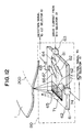
- Fig. 12 is a schematic perspective view showing a construction of an optical head of an optical disc apparatus according to the sixth embodiment of the invention.
- the sixth embodiment has substantially the same construction as that of the sixth optical head 60 shown in Fig. 11 except a third beam splitter 81 and a waveguide mirror 82 and the same parts and components as those shown in Fig. 11 are designated by the same reference numerals. That is, an optical head of the-sixth embodiment, namely, a-seventh optical head 80 is constructed in the following manner.
- the third beam splitter 81 is arranged on the optical path between the waveguide lens 64 and the beam splitter 66.
- the waveguide mirror 82 is arranged in the direction of the waveguide divided in the direction different from the direction of the first beam splitter 66 and the position of the mirror 82 is set to a position where the waveguide light reflected by the waveguide mirror 82 passes through the second beam splitter 72.
- the driving current is supplied to the first semiconductor laser 63.
- the laser 63 emits a laser beam from one edge surface of the optical waveguide 62.
- the laser beam propagates as a waveguide light.
- the waveguide light is converted into the parallel light by the first waveguide lens 64 and is divided into the transmission light and the reflected light by the third beam splitter 81.
- the transmission light is transferred to the first converging grating coupler 65 through the first beam splitter 66.
- the reflected light is reflected by the waveguide mirror 82 and enters the second converging grating coupler 71 through the second beam splitter 72.
- the subsequent operations are executed in a manner similar to those of the sixth optical head 60 in the fifth embodiment of the invention.
- the sixth embodiment in addition to the effects by the foregoing fifth embodiment, by dividing the waveguide light emitted from one semiconductor laser into two lights by the third beam splitter 81 and guiding to the respective converging grating couplers, the number of semiconductor lasers which are used can be reduced.
- the sixth embodiment has been described on the assumption that the number of thicknesses of the disc substrates is set to two kinds of thicknesses, the invention can be also applied to three or more kinds of thicknesses of the disc substrates.
- N converging grating couplers and (N - 1) beam splitters for dividing the waveguide light emitted from the semiconductor laser.
- N - 1 the number of kinds of thicknesses of the disc substrates is equal to N
- N - 1 the number of kinds of thicknesses of the disc substrates
- N - 1 the number of kinds of the disc substrates
- N - 1 the number of kinds of thicknesses of the disc substrates
- the beam splitters so as to set division ratios of the light quantities of the beam splitters as follows. 1 : N - 1 1 : N - 2 1 : N - 3 . . . 1 : 1
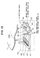
- Fig. 13 is a schematic perspective view showing a construction of an optical head of an optical disc apparatus according to the seventh embodiment of the invention.
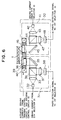
- Fig. 14 is a block diagram showing a construction of the optical disc apparatus.
- Reference numeral 91 denotes an SAW (surface acoustic wave) transducer arranged on the optical waveguide 62 so that a surface acoustic wave generated by the SAW transducer crosses the optical path of the waveguide light emitted from the first waveguide lens 64.
- the SAW transducer 91 is constructed by a cross finger electrode comprising a piezoelectric transducer of ZnO or the like.
- Reference numeral 92 indicates a surface acoustic wave generated by the SAW transducer 91; 96 a third converging grating coupler formed on the optical path of the waveguide light which has been diffracted by such a surface acoustic wave 92 and propagates in the first direction; and 97 a fourth converging grating coupler which is likewise formed on the optical path of the waveguide light propagating in the second direction.
- Each of the couplers 96 and 97 emits the waveguide light to a region out of the optical waveguide 62 and converges onto the optical disc 1.
- Reference numeral 93 denotes a fourth beam splitter which is arranged between the first waveguide lens 64 and the progressing path of the surface acoustic wave 92 and reflects the waveguide light returned into the optical waveguide 62 through the third or fourth converging grating couplers 96 and 97 after it had been reflected by the optical disc 1.
- Reference numeral 94 denotes a third waveguide converging lens which is arranged on the optical path of the return light reflected by the fourth beam splitter 93 and converges the return light and 95 indicates a third photo detector which is coupled to the side surface of the optical waveguide 62 and detects the return light converged by the third waveguide converging lens 94.
- the first semiconductor laser 63 emits a laser beam from one edge surface of the optical waveguide 62.
- the laser beam propagates as a waveguide light.
- the waveguide light is converted into the parallel light by the first waveguide lens 64 and transmits through the fourth beam splitter 93. After that, the light transverses the surface acoustic wave 92 generated from the SAW transducer 91. At this time, the propagating direction of the parallel waveguide light is changed by an acoustic optical interaction with the surface acoustic wave 92.
- the waveguide light can be propagated in any one of the directions of the third and fourth converging grating couplers 96 and 97 in accordance with frequencies of high-frequency voltages which are applied to the SAW transducer 91 from the outside (it is now assumed that the frequencies of the high-frequency voltages are set to f 1 and f 2 , respectively).
- the high-frequency voltage of the frequency f 1 is applied to the SAW transducer 91 from the outside, thereby allowing the parallel waveguide light to enter the third converging grating coupler 96.
- the third converging grating coupler 96 extracts the parallel waveguide light to a region out of the optical waveguide 62 and converges onto the information track 200 on the first optical disc 1.
- the reflected light from the disc surface again enters the optical waveguide 62 through the third grating coupler 96 and propagates as a return waveguide light in the opposite direction.
- the progressing direction of the waveguide light is changed by the surface acoustic wave 92 and, after that, the waveguide light is reflected in the direction of the third waveguide converging lens 94 by the fourth beam splitter 93.
- the third waveguide converging lens 94 converges the return light to the third photo detector 95.
- the third photo detector 95 detects the information signal and the servo signals such as focusing error signal, tracking error signal, and the like which have been recorded on the first optical disc 1 on the basis of an intensity and an intensity distribution of the return light and generates to the outside.
- an eighth optical head 90 emits the intensity modulated laser beam, thereby recording or erasing the information signal onto/from the first optical disc 1.
- the high-frequency voltage of the frequency f 2 is applied to the SAW transducer 91 from the outside, thereby allowing the parallel waveguide light to enter the fourth converging grating coupler 97.
- the subsequent operations are executed in a manner similar to those in the case of the first optical disc.
- the substrate 61 is supported from the head base by a focusing actuator and a tracking actuator (not shown).
- the position of the substrate 61 itself is controlled by the servo signals so that the laser beam is accurately irradiated onto the information track 200 on the disc.
- the optical disc 1, cartridge 2, first linear motor 4, discrimination hole 7, LED 8, photo diode 9, tracking control circuit 11, focusing control circuit 13, linear motor control circuit 15, spindle control circuit 17, spindle motor 18, signal processing circuit 19, LD driving circuit 20 and system controller 22 are the same as those in the optical disc apparatus in the third embodiment according to the invention.
- Reference numeral 90 denotes the eighth optical head which is constructed by the waveguide substrate, focusing actuator, tracking actuator, head base and the like.
- Reference numeral 85 denotes a constant voltage generating circuit which receives a control signal from the system controller 22 and generates a predetermined voltage V i .
- Reference numeral 86 denotes a V/f converting circuit which receives the voltage V i from the constant voltage generating circuit 85 and generates a high-frequency signal of a frequency f which is proportional to V i .
- Reference numeral 87 denotes an SAW driving circuit to apply a high-frequency voltage of the same frequency as the frequency f of the high-frequency signal supplied from the V/f converting circuit 86 to the SAW transducer 91 of the eighth optical head 90.
- the system controller 22 determines that the disc in the loaded cartridge 2 is the second optical disc by the detection signal of the photo diode 9, so that the controller 22 generates a control signal to the constant voltage generating circuit 85 so as to generate the voltage V 2 .
- the V/f converting circuit 86 converts the input voltage V 2 into the frequency f 2 , so that the SAW driving circuit 87 applies the high-frequency voltage of the frequency f 2 to the SAW transducer 91 of the eighth optical head 90.
- the laser beam is irradiated from the second converging grating coupler 97 and is converged without an aberration onto the information track 200 on the second optical disc having the disc substrate of the thickness d 2 .
- the third photo detector 95 of the eighth optical head 90 detects a focusing error signal and a tracking error signal from the reflected light from the optical disc and supplies to the tracking control circuit 11 and the focusing control circuit 13. Further, the information signal on the disc is supplied to the signal processing circuit 19 and the spindle control circuit 17.
- the system controller 22 generates a control signal to the constant voltage generating circuit 85 so as to generate the voltage V 1 .
- the V/f converting circuit 86 converts the input voltage V 1 into the frequency f 1 , so that the SAW driving circuit 87 applies the high-frequency voltage of the frequency f 1 to the SAW transducer 91 of the eighth optical head 90. Therefore, in the eighth optical head 90, a laser beam is emitted from the first converging grating coupler 96 and is converged without an aberration onto the information track 200 on the first optical disc having the disc substrate of the thickness d 1 .
- the other operations are executed in a manner similar to those in the case of the foregoing second optical disc.
- the number of semiconductor lasers which are necessary in the eighth optical head 90 is only one and each of the converging grating couplers does not simultaneously emit the laser beam, so that an emission power of the semiconductor laser can be efficiently taken out of the converging grating coupler. That is, the optical head having a transfer efficiency better than that of the seventh optical head 80 in the foregoing sixth embodiment can be provided.
- the fourth beam splitter 93 between the waveguide lens 64 and the SAW transducer 91, the return lights from the two converging grating couplers can be detected by one photo detector.
- the number of thicknesses of the disc substrates has been set to two kinds of thicknesses in the embodiment, the invention can be also obviously applied to three or more kinds of thicknesses of the disc substrates.
- the number of converging grating couplers is increased in accordance with the number of kinds of thicknesses and the optical paths are switched by the SAW transducer 91 in accordance with the increased number of such couplers.
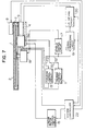
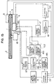
- Fig. 15 is a block diagram showing a construction of the optical disc apparatus in the eighth embodiment.
- reference numeral 1 denotes the first or second optical disc; 2 the cartridge; 4 the linear motor; 7 the discrimination hole; 8 the LED; 9 the photo diode; 13 the focusing control circuit; 15 the linear motor control circuit; 17 the spindle control circuit; 18 the spindle motor; 19 the signal processing circuit; 20 the LD driving circuit; 22 the system controller; 85 the constant voltage generating circuit; 86 the V/f converting circuit; and 87 the SAW driving circuit.
- the above component elements are the same as those in the optical disc apparatus in the seventh embodiment of Fig. 14 and their detailed descriptions are omitted here.
- Reference numeral 90 denotes an optical head which is substantially the same as the eighth optical head 90 mentioned above except that the optical head in the eighth embodiment does not have a tracking actuator. Therefore, the optical head in Fig. 15 is also referred to as an eighth optical head 90 hereinafter for convenience of explanation.
- Reference numeral 100 denotes a tracking error detecting circuit which receives a tracking error signal from the third photo detector 95 of the eighth optical head 90 and generates a tracking error voltage V TE to an adder 101, which will be explained hereinafter.
- Reference numeral 101 denotes the adder.
- the V/f converting circuit 86, SAW driving circuit 87, tracking error detecting circuit 100, and adder 101 construct a tracking control circuit 102. That is, it is the inventive point of the eighth embodiment that the tracking control is executed by using the SAW transducer 91 of the eighth optical head 90.
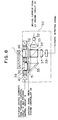
- Fig. 16 is an enlarged schematic perspective view of the converging grating coupler, SAW transducer, and portion where a surface acoustic wave has been formed.
- the waveguide light which enters the converging grating coupler is oscillated between solid lines and broken lines in accordance with a microchange of the frequency of the surface acoustic wave.
- Such an oscillation angle is called a deflection angle (shown by ⁇ ). Therefore, the emission light from the converging grating coupler is also oscillated and the converged spot moves. Since the deflecting angle ⁇ changes in almost proportional to the frequency of the surface acoustic wave, by changing the frequency in accordance with the tracking error amount, the converged spot can be accurately positioned onto the information track.
- the system controller 22 controls the constant voltage generating circuit 85 so as to set the output voltage V; into V 2 .
- the output voltage V TE of the tracking error detecting circuit 100 has been initialized to "0".
- the V/f converting circuit 86 changes a frequency f s of an output signal in accordance with the input voltage V 0 .
- the SAW driving circuit 87 applies a high-frequency voltage of the frequency f 2 to the SAW transducer 91 of the eighth optical head 90.
- the laser beam is emitted from the fourth converging grating coupler 97 and is converged without an aberration onto the information track on the second optical disc.
- the reflected light from the disc is detected by the third photo detector 95.
- a tracking error signal is supplied to the tracking error detecting circuit 100.
- a focusing error signal is supplied to the focusing control circuit 13.
- the information signal is supplied to the spindle control circuit 17 and the signal processing circuit 19.
- the tracking error detecting circuit 100 produces the tracking error voltage V TE in accordance with a track deviation amount of the converged spot on the information track 200 and supplies to the adder 101.
- the output signal frequency f s of the V/f converting circuit 86 is deviated from the frequency f 2 by a value corresponding to the tracking error (assumes d f ).
- the frequency of the driving voltage to the SAW transducer 91 changes, the emitting position of the light from the fourth converging grating coupler 97 changes and the position of the converged spot on the optical disc 1 changes for the track.
- the system controller 22 controls the constant voltage generating circuit 85, thereby setting the output voltage V i into V 1 .
- the V/f converting circuit 86 generates a high-frequency signal of the frequency f 1 to the SAW driving circuit 87 and the SAW driving circuit 87 applies a high-frequency voltage of the frequency f 1 to the SAW transducer 91 of the eighth optical head 90. Consequently, in the eighth optical head 90, the laser beam is emitted from the third converging grating coupler 96 and is converged without an aberration onto the information track 200 on the first optical disc.
- the tracking error detecting circuit 100 supplies the tracking error voltage V TE to the adder 101 from the input signal T 1 .
- Fig. 17 is a graph showing the principle of the tracking control of the embodiment and shows the relations among the V 0 and f s and the deflection angle of the waveguide light in the eighth optical head 90.
- the oscillation angle of the waveguide light can be finely varied. Therefore, by varying the emitting positions of the light beams from the two converging grating couplers, the converged spot can be allowed to trace on the track.
- the change-over of the waveguide lights which enter the converging grating couplers and-the tracking control can be executed by the SAW transducer 91.
- the optical head can be simplified and the number of manufacturing steps can be reduced.
- the surface acoustic wave 92 is located between the fourth beam splitter 93 and the two converging grating couplers, the return waveguide light from the optical disc 1 is not influenced by the tracking control on the optical path after the surface acoustic wave 92. Therefore, the converging position on the third photo detector is not moved by the tracking control, so that a deterioration in photo detection signal can be prevented.
- the SAW transducer has been used as both of the optical path switching means and the optical path deflecting means for tracking control
- the SAW transducer can be also provided for the optical head only for the tracking control.
Landscapes
- Physics & Mathematics (AREA)
- Optics & Photonics (AREA)
- Optical Head (AREA)
- Optical Recording Or Reproduction (AREA)
Description
- The invention relates to an optical disc apparatus which can record, reproduce, or erase information signals onto/from both of an optical disc having a recording density similar to that of a conventional CD (compact disc) and an optical disc having a recording density higher than the above recording density.
- In recent years, in addition to an optical disc apparatus only for reproduction such as a CD player or the like, an optical disc apparatus which can record and reproduce an information signal is actively being developed.
- Ordinarily, the recording and reproduction of an information signal onto/from an optical disc are executed by converging a beam which is radiated from a semiconductor laser or the like onto a recording layer of the optical disc by a lens. The recording layer here denotes a pit layer in the case of a CD and is a layer in which a deformation, a change in optical constant, a formation of a magnetic domain, or the like is performed by a converged laser beam in the case of a recordable optical disc. To raise a recording density of the optical disc, it is necessary to reduce a spot diameter D of the converged beam. There is the following relation among the spot diameter D, a numerical aperture NA of the lens, and a wavelength λ of the laser beam.

- The above equation (1) denotes that the beam spot diameter D decreases by using a lens of a large NA. That is, by increasing NA, the high density recording can be executed.
- When NA of the lens increases, however, an aberration of the converged beam due to an inclination error of the disc called a tilt increases. Particularly, a coma aberration increases. There is the following relation among a wave front aberration Wc of the coma, a tilt angle α, and NA when using a thickness d and a refractive index n of the disc substrate.

- The above equation (2) denotes that in the case of using a lens of NA which is larger than that of the conventional lens, even if a tilt angle is identical, the coma aberration increases. It will be understood from the equation (2), however, that there is an effect to suppress the coma aberration by setting the thickness d of the disc substrate to be thin. In the optical disc for the high density recording, therefore, it is preferable that the thickness of the disk substrate is thinner than that of the conventional optical disc, so that an optical head using an objective lens corresponding to the thin disc substrate is needed.
- On the other hand, even in the optical disc apparatus corresponding to the high density recording, it is preferable that the conventional optical disc of a thick substrate can be also reproduced so that a great amount of conventional software resources can be utilized.
- However, the optical head which has been designed for a thin substrate cannot be used for an optical disc of a thick substrate. The reasons will now be described hereinbelow. The objective lens for an optical disc has been designed so as to set off a spherical aberration which occurs when the converged beam passes in the disc substrate. Since such an aberration is corrected in accordance with the thickness of the disc substrate, the aberration correction is not accurately performed for the converged beam which passes through the disc substrate having a thickness different from the design value. The above point will now be explained with reference to the drawing. Figs. 18A and 18B are schematic side elevational views for explaining a situation of the occurrence of the aberration due to the disc substrates having different thicknesses. Fig.18A is a diagram in the,case of using-an objective lens which has been designed for a thin disc substrate and shows traces of lights in a state in which a beam has been converged through the disc substrate having the same thickness as the design value. In the diagram, a broken line indicates the surface of a recording layer and all of the lights emitted from the objective lens are converged to one point O on the recording layer surface. Fig. 18B is a diagram in the case of using an objective lens which has been designed for the same thin disc substrate as that of Fig. 18A and shows traces of lights in a state in which the beam has been converged through the disc substrate having a thickness which is thicker than the design value. In Fig. 18B, the lights emitted from the outermost peripheral portion of the objective lens are converged to a point O' on the recording layer surface. However, the light locating near the optical axis is converged at the front side. Such a phenomenon is called a spherical aberration. When such an aberration occurs, the objective lens cannot converge the light beam until what is called a diffraction limit. Therefore, in the case of using the objective lens whose aberration has been corrected for a thin disc substrate, an information signal cannot be recorded, reproduced, or erased onto/from an optical disc having a thick disc substrate. Similarly, in the case of using the objective lens whose aberration has been corrected for a thick disc substrate, an information signal cannot be recorded, reproduced, or erased on to or from an optical disc having a thin disc substrate.
- EP-A-0 452 953 (prior art under Article 54(3) EPC) describes an optical disc recording/reproducing apparatus for use with both a standard optical disc and a two-sided optical disc. When a two-sided optical disc is used, an optical plate is placed in front of a focusing lens, the optical plate being removed when a standard optical disc is used.
- JP-A-52 153 705 reflecting the preamble of
claim 1 describes an optical disc optical disc reproducing apparatus for use with both thin and thick discs. The thickness of a disc is detected and a transparent medium is automatically attached or detached between a focusing lens and the disc so as to correct the aberration of the focusing lens. - EP-A-0 144 436 describes an optical recording and reproducing apparatus which is able to distinguish between an erasable optical disc and a non-erasable optical disc by detecting the presence of absence of a mark in the disc jacket.
- In consideration of the above, it would be desirable to provide an optical disc apparatus which can record, reproduce or erase information signals on to or from a plurality of optical discs in which the thicknesses of the disc substrates are different.
- In accordance with the present invention, there is provided apparatus for recording, reproducing or erasing information on to or from an optical disc as defined by
claim 1. -
- Fig. 1 is a constructional diagram of an optical disc apparatus according to the first embodiment of the invention;
- Fig. 2 is a plan view showing an arrangement of a main section of the optical disc apparatus in the first embodiment;
- Figs. 3A and 3B are perspective views of cartridges of optical discs in the first embodiment;
- Figs. 4A and 4B are schematic diagrams showing cross sections of the optical discs and states of convergences by objective lenses in the first embodiment;
- Fig. 5 is a constructional diagram of an optical disc apparatus according to the second embodiment of the invention;
- Fig. 6 is a detailed constructional diagram of optical heads in the second embodiment;
- Fig. 7 is a constructional diagram of an optical disc apparatus according to the third embodiment of the invention;
- Fig. 8 is a detailed constructional diagram of an optical head in the third embodiment;
- Figs. 9A and 9B are a detailed constructional diagram of an optical head of an optical disc apparatus according to the fourth embodiment of the invention;
- Fig. 10 is a cross sectional view showing optical discs whose substrate thicknesses are different and converging states by convergence grating couplers which have been designed in correspondence to the optical discs according to the fifth embodiment, respectively;
- Fig. 11 is a schematic perspective view showing a construction of an optical head of an optical disc apparatus in the fifth embodiment;
- Fig. 12 is a schematic perspective view showing a construction of an optical head of an optical disc apparatus according to the sixth embodiment of the invention;
- Fig. 13 is a schematic perspective view showing a construction of an optical head of an optical disc apparatus according to the seventh embodiment of the invention;
- Fig. 14 is a block diagram showing a construction of the optical disc apparatus in the seventh embodiment;
- Fig. 15 is a block diagram showing a construction of an optical disc apparatus according to the eighth embodiment of the invention;
- Fig. 16 is a schematic enlarged perspective view showing a convergence grating coupler of an optical head, an SAW transducer, and a portion in which surface acoustic waves have been formed in the eighth embodiment;
- Fig. 17 is a characteristic diagram for explaining the principle of the tracking control in the eighth embodiment; and
- Figs. 18A and 18B are schematic side elevational views showing occurring situations of aberrations due to disc substrates having different thicknesses.
- Embodiments of the invention will be described hereinbelow on the assumption that thicknesses of disc substrates are set to two kinds of thicknesses.
- Fig. 1 is a constructional diagram of an optical disc apparatus in the first embodiment of the invention. Fig. 2 is a plan view showing an arrangement of a main section of the embodiment. Figs. 3A and 3B are perspective views of cartridges of optical discs in the embodiment.
- In Figs. 1 to 3A and 3B,
reference numeral 1 denotes a first or second optical disc. Thicknesses of disc substrates of both of the first and second optical discs are different.Reference numeral 2 denotes a cartridge which encloses theoptical disc 1 and protects. Thecartridge 1 is made of plastics or the like.Reference numeral 3 denotes a first optical head and 5 indicates a second optical head. Each of the optical heads is constructed by a converging optical system comprising: an objective lens; a semiconductor laser; a photo detector; a beam splitter; and the like (all of the above components are not shown). Each of the optical head detects an information signal, a focusing error signal, and a tracking error signal which have been recorded on theoptical disc 1 on the basis of an intensity or an intensity distribution of the reflected lights of a laser beam irradiated onto theoptical disc 1 and generates a photo detection signal to the outside. An information signal is recorded onto or erased from theoptical disc 1 by modulating an intensity of the laser beam. Both of the optical heads have bases to hold the above optical devices and actuators. A reproduction information signal, a focusing error signal, and a tracking error signal which are generated from the photo detector of the firstoptical head 3 are expressed by S1, F1, and T1, respectively. Similar signals which are generated from the photo detector of the secondoptical disc 5 are also expressed by S2, F2, and T2, respectively.Reference numeral 4 denotes a first linear motor which is arranged below theoptical disc 1 and moves the firstoptical head 3 in the radial direction of the disc in parallel with the disc surface.Reference numeral 6 denotes a second linear motor which is arranged below theoptical disc 1 so as to face the firstlinear motor 4 and moves the secondoptical head 5 in a manner similar to the firstoptical head 3. - As shown in Fig. 2, the second
linear motor 6 is extended until the further outside of the outermost peripheral portion of theoptical disc 1. Therefore, when the secondoptical head 5 moves to the outermost side, theoptical head 5 is projected from the lower surface of the optical disc.Reference numeral 7 denotes a discrimination hole formed on the surface of thecartridge 2. - The cartridge in the embodiment will now be described with reference to Figs. 3A and 3B. The
discrimination hole 7 is closed in the case where theoptical disc 1 enclosed in the cartridge is the first optical disc shown in Fig. 3A and is open in the case where it is the second optical disc shown in Fig. 3B.Reference numeral 23 denotes a slide shutter. Since the optical disc apparatus of the embodiment has two optical heads, two slide shutters are provided. When the cartridges are removed from the optical disc apparatus, the slide shutters are closed to protect the internal discs from dusts. -
Reference numeral 8 denotes a light emitting diode (hereinafter, abbreviated to an LED) which is arranged so as to be located over thediscrimination hole 7 when thecartridge 2 has been loaded into the optical disc apparatus of the embodiment.Reference numeral 9 denotes a photo diode arranged at a position so as to face theLED 8 through thecartridge 2. Thephoto diode 9 generates a detection signal to asystem controller 22, which will be explained hereinlater.Reference numeral 10 denotes a first selector for selecting either one of the first group of photo detection signals (S1, F1, and T1) of the firstoptical head 3 and the second group of photo detection signals (S2, F2, and T2) of the secondoptical head 5 and for outputting the selected signals.Reference numeral 11 denotes a tracking control circuit which receives the tracking error signal T1 or T2 from among the output signals of thefirst selector 10 and generates a tracking actuator driving signal to asecond selector 12, which will be explained hereinlater. Further,reference numeral 12 denotes the second selector to select either an actuator of the firstoptical head 3 or an actuator of the secondoptical head 5 as a destination to which the tracking actuator driving signal is supplied.Reference numeral 13 denotes a focusing control circuit which receives the focusing error signal F1 or F2 from among the signals which are generated from thefirst selector 10 and generates a focusing actuator driving signal to athird selector 14, which will be explained hereinlater. Further,reference numeral 14 denotes the third selector for selecting either the actuator of the firstoptical head 3 or the actuator of the secondoptical head 5 as a destination to which the focusing actuator driving signal is supplied.Reference numeral 15 denotes a linear motor control circuit which supplies a driving signal to afourth selector 16, which will be explained hereinlater, by a control signal which is supplied from thesystem controller 22, which will be described hereinlater.Reference numeral 16 denotes the fourth selector to select either the firstlinear motor 4 or the secondlinear motor 6 as an output destination of the driving signal supplied from the linearmotor control circuit 15.Reference numeral 17 denotes a spindle control circuit which receives the reproduction information signal S1 or S2 and generates a control current to aspindle motor 18, which will be explained hereinlater.Reference numeral 18 denotes the spindle motor to rotate theoptical disc 1.Reference numeral 19 denotes a signal processing circuit for executing signal processes such as demodulation and/or decoding or the like to the input signal S1 or S2, for converting into an audio signal or the like, or for outputting the information signal to be recorded onto theoptical disc 1 to anLD driving circuit 20, which will be explained hereinlater.Reference numeral 20 denotes the LD driving circuit to supply a driving current for allowing laser beams to be emitted from the semiconductor lasers of both of the optical heads to afifth selector 21, which will be explained hereinlater.Reference numeral 21 denotes the fifth selector to switch the output destination of the above driving current to either one of the first and secondoptical heads system controller 22, which will be explained hereinlater. Thesystem controller 22 generates the driving current for allowing theLED 8 to emit the light and receives the detection signal from thephoto diode 9 and generates control signals to the first tofifth selectors system controller 22 also generates control signals to the linearmotor control circuit 15 and thesignal processing circuit 19. In Fig. 1, switching terminals in the first tofifth selectors - The first optical disc is a CD or an optical disc having a recording density similar to that of the CD and a thickness of the disc substrate is set to d1 as shown in Fig. 4A. For instance, assuming that the optical disc shown in Fig. 4A is a CD, d1 = 1.2mm. The second optical disc is an optical disc which can execute a recording at a higher density than that of the first optical disc and a thickness of the disc substrate assumes d2 as shown in Fig. 4B. To reduce the aberration of the converged spot due to a tilt error, the thickness d2 of the second optical disc is designed so as to be smaller than d1. For example, d2 = 0.3 mm.
- The first
optical head 3 has, for instance, a semiconductor laser of a wavelength of 780 nm and an objective lens of an NA of 0.45, so that the laser beam can be converged to a spot diameter φ of about 2.1 µm. In addition, an optical design of the objective lens has been made so as to correct the aberration by the disc substrate of the thickness d1. The secondoptical head 5 has, for instance, the same semiconductor laser as that of the first optical head and an objective lens of an NA of 0.8, so that the laser beam can be converged until a spot diameter of 1.2 µm. Moreover, an optical design of the objective lens has been made so as to correct the aberration by the disc substrate of the thickness d2. - The operation of the optical disc apparatus of the embodiment constructed as mentioned above will now be described hereinbelow.
- First, the case where the
cartridge 2 enclosing the second optical disc has been loaded into the optical disc apparatus of the embodiment will be described. When thecartridge 2 is loaded, theLED 8 emits the light and thephoto diode 9 detects the presence or absence of a transmission light which passes through thediscrimination hole 7. As already described in conjunction with Figs. 3A and 3B, since thediscrimination hole 7 is open in the case of the second optical disc, thephoto diode 9 detects the transmission light and generates a detection signal to thecontroller 22. Thecontroller 22 determines that the disc in the loadedcartridge 2 is the second optical disc, so that thecontroller 22 supplies control signals to the first tofifth selectors optical head 5 is selected as an output destination of the driving current which is supplied from theLD driving circuit 20. The photo detector of the secondoptical head 5 is selected as an input destination of thetracking control circuit 11, focusingcontrol circuit 13,spindle control circuit 17, andsignal processing circuit 19. The actuator of the secondoptical head 5 is selected as an output destination of the actuator driving signals of thetracking control circuit 11 and focusingcontrol circuit 13. The secondlinear motor 6 is selected as an output destination of the driving current of the linearmotor control circuit 15. - Therefore, the second
optical head 5 irradiates the laser beam and converges onto an information track on theoptical disc 1 without an aberration. Simultaneously, the secondoptical head 5 detects the reflected lights from the disc and generates the information signal S2, focusing error signal F2, and tracking error signal T2. Those signals are supplied through thefirst selector 10 to the respective circuits. That is, the signal S2 is supplied to thespindle control circuit 17 andsignal processing circuit 19. The signal F2 is supplied to the focusingcontrol circuit 13. The signal T2 is supplied to thetracking control circuit 11. Thetracking control circuit 11 produces the tracking actuator driving signal in accordance with the signal T2 and supplies to the actuator of the secondoptical head 5 through thesecond selector 12, thereby eliminating the tracking error. In a manner similar to the above, the focusingcontrol circuit 13 also produces the focusing actuator driving signal in accordance with the signal F2 and supplies to the actuator of the secondoptical head 5 through thethird selector 14, thereby eliminating the focusing error. The linearmotor control circuit 15 generates the driving current to thelinear motor 6 in response to the control signal from thesystem controller 22, thereby moving the secondoptical head 5 in the inner or outer rim direction of theoptical disc 1. Thespindle control circuit 17 extracts a clock component from the information signal S2 and controls thespindle motor 18, thereby rotating theoptical disc 1 at a constant linear velocity (CLV) or a constant angular velocity (CAV) or the like. Thesignal processing circuit 19 executes signal processes such as demodulation, decoding, and the like to the information signal S2 in the reproducing mode and generates to the outside as audio or video signals or the like. On the other hand, thesignal processing circuit 19 executes signal processes such as encoding, modulation, and the like to the audio or video signals or the like which have been supplied from the outside in the recording mode and generates to theLD driving circuit 20 as a recording signal. Until thecartridge 2 is loaded, the secondoptical head 5 records or reproduces the information signal onto/from the secondoptical disc 1. - On the other hand, in the case where the
cartridge 2 enclosing the first optical disc has been loaded into the optical disc apparatus of the embodiment, since thediscrimination hole 7 is closed, thephoto diode 9 doesn't detect the transmission light. Therefore, thesystem controller 22 determines that the disc in thecartridge 2 is the foregoing first optical disc. Thus, thecontroller 22 generates control signals to the first tofifth selectors optical head 3 is selected as an output destination of the driving current which is supplied from theLD driving circuit 20. The photo detector of the firstoptical head 3 is selected as an input destination of thetracking control circuit 11, focusingcontrol circuit 13,spindle control circuit 17, andsignal processing circuit 19. The actuator of the firstoptical head 3 is selected as an output destination of the actuator driving signals of thetracking control circuit 11 and focusingcontrol circuit 13. The firstlinear motor 4 is selected as an output destination of the driving current of the linearmotor control circuit 17. Therefore, the firstoptical head 3 irradiates the laser beam and converges onto the information track on theoptical disc 1 without an aberration. Simultaneously, the reflected lights from the disc are detected and generated as the information signal S1, focusing error signal F1, and tracking error signal T1. The above signals are supplied through thefirst selectors 10 to the respective circuits. That is, the signal S1 is supplied to thespindle control circuit 17 andsignal processing circuit 19. The signal F1 is supplied to the focusingcontrol circuit 13. The signal T1 is supplied to the trackingerror detecting circuit 11. The subsequent operations are similar to those in the case of the second optical disc mentioned above. - In the case where the objective lens of the second optical head is a lens of a high NA and a short operating distance, it is necessary to set an interval between the second
optical head 5 and the surface of theoptical disc 1 to be fairly narrower than that in the case of the firstoptical head 5. Therefore, while the first optical disc is loaded, thecontroller 22 controls the secondlinear motor 6, thereby moving the secondoptical head 5 to the outside of the disc surface as shown in Fig. 2. Due to this, it is possible to prevent that the objective lens of the secondoptical head 5 collides with theoptical disc 1 due to a surface oscillation. - As described above, according to the embodiment, by providing the first
optical head 3 and secondoptical head 5 having convergence optical systems corresponding to the thicknesses of the disc substrates of the first and second optical discs, the signal can be preferably recorded, reproduced, or erased by the optical head suitable for the thickness of each disc substrate. Moreover, by providing thediscrimination hole 7 formed on thecartridge 2 and the disc discriminating means comprising theLED 8 to detect the opening/closure of thediscrimination hole 7 and thephoto diode 9, merely by loading thecartridge 2, each of the optical heads can be automatically accurately selected. - Fig. 5 shows a constructional diagram of an optical disc apparatus according to the second embodiment of the invention. In the diagram, the second embodiment differs from the foregoing first embodiment with respect to a point that a third
optical head 30 is arranged in place of the first and secondoptical heads fourth selectors tracking control circuit 11 and the focusing actuator driving current which is generated from the focusingcontrol circuit 13 are directly supplied to the thirdoptical head 30. The driving current which is generated from the linearmotor control circuit 15 is directly supplied to the firstlinear motor 4. - Further, Fig. 6 shows a detailed constructional diagram of the third
optical head 30 in the second embodiment of the invention. In the diagram,reference numeral 1 denotes the first or second optical disc; 32 a first semiconductor laser as a light source; 33 a first collimating lens for converting a laser beam from thefirst semiconductor laser 32 into a parallel beam; 34 first beam splitter to divide the beam into two beams; 35 a first mirror to change the direction of the beam; 36 a first objective lens to converge the beam onto theoptical disc 1; 37 a first detecting lens to converge the reflected lights which have been divided by thebeam splitter 34; and 38 a first photo detector to obtain an information reproduction signal, a focusing error signal, and a tracking error signal from the converged reflected lights. Theabove components 32 to 38 construct a first convergingoptical system 31. -
Reference numeral 39 denotes a lens holder to hold the firstobjective lens 36 and a secondobjective lens 46, which will be explained hereinlater.Reference numeral 40 denotes an actuator to support thelens holder 39. The driving currents are supplied from thetracking control circuit 11 and focusingcontrol circuit 13 to theactuator 40. -
Reference numeral 42 denotes a second semiconductor laser as a light source; 43 a second collimating lens to convert a laser beam from thesecond semiconductor laser 42 into a parallel beam; 44 a second beam splitter to divide the beam into two beams; 45 a second mirror to change the direction of the beam; 46 the second objective lens to converge the beam onto theoptical disc 1; 47 a second detecting lens to converge the reflected lights which have been divided by thesecond beam splitter 44; and 48 a second photo detector to obtain the information reproduction signal, focusing error signal, and tracking error signal from the converged reflected lights. Theabove components 42 to 48 construct a second convergingoptical system 41. The above first convergingoptical system 31, the second convergingoptical system 41, and theactuator 40 are mounted on a same base member (not shown) and construct the thirdoptical head 30. The base member is ordinarily made of aluminum or the like and is attached to the firstlinear motor 4. - In a manner similar to the case which has been described in the first embodiment of the invention, for instance, the first
objective lens 36 is designed so that NA = 0.45 and the aberration by the disc substrate of a thickness d1 is corrected. The secondobjective lens 46 is designed so that, for instance, NA = 0.8 and the aberration by the disc substrate of a thickness d2 is corrected. - The operation of the optical disc apparatus of the embodiment constructed as mentioned above will now be described hereinbelow. First, the case of the second optical disc will be explained. When the
cartridge 2 is loaded into the optical disc apparatus of the embodiment, theLED 8 emits the light and thephoto diode 9 detects the presence or absence of the transmission light which passes through thediscrimination hole 7. If the transmission light has been detected, thesystem controller 22 determines that the disc in the loadedcartridge 2 is the second optical disc, so that thecontroller 22 selects the second convergingoptical system 41 of the thirdoptical head 30. That is, thesystem controller 22 generates control signals to the first andfifth selectors second semiconductor laser 42 and the second photo detector 48 operative. The laser beam emitted from thesecond semiconductor laser 42 is converted into the parallel beam by thesecond collimating lens 43. The parallel beam is converged onto the secondoptical disc 1 by the secondobjective lens 46 through thesecond beam splitter 44 and thesecond mirror 45. The laser beam reflected by the disc is again converted into the parallel beam by the secondobjective lens 46 and is separated from the optical axis by thesecond beam splitter 44 through thesecond mirror 45 and is converged onto the second photo detector 48 by the second detectinglens 47. - The second photo detector 48 produces the information signal, focusing error signal, and tracking error signal from the converged reflected light from the disc and supplies to the
first selector 10. Theactuator 40 finely moves thelens holder 39 in the tracking and focusing directions by the driving currents from thetracking control circuit 11 and the focusingcontrol circuit 13, thereby accurately converging the laser beam onto an information track on theoptical disc 1. - Since the operations of the first
linear motor 4,first selector 10, trackingcontrol circuit 11, focusingcontrol circuit 13, linearmotor control circuit 15,spindle control circuit 17,spindle motor 18,signal processing circuit 19,LD driving circuit 20,fifth selector 21, andsystem controller 22 are substantially the same as the optical disc apparatus of the first embodiment mentioned above, their descriptions are omitted here. - On the other hand, in the case of the first optical disc, since the
photo diode 9 doesn't detect the transmission light, thesystem controller 22 decides that the disc in the loadedcartridge 2 is the first optical disc mentioned above, so that thecontroller 22 selects the first convergingoptical system 31 of the thirdoptical head 30. That is, thesystem controller 22 generates control signals to the first andfifth selectors first semiconductor laser 32 and thefirst photo detector 38 operative. The operation of the first convergingoptical system 31 is substantially the same as that of the second convergingoptical system 41 mentioned above. Until thecartridge 2 is unloaded, the recording, reproduction, or erasure of the information signal onto/from the first optical disc is executed by the first convergingoptical system 31. - As described above, according to the second embodiment, in addition to the effect by the first embodiment, since the first converging
optical system 31 and the second convergingoptical system 41 are mounted on the same base and construct the thirdoptical head 30, the linear motor can be commonly used as a single part and the number of parts can be reduced. - Fig. 7 shows a constructional diagram of an optical disc apparatus according to the third embodiment of the invention. In the diagram, the third embodiment differs from the second embodiment with respect to a point that a fourth
optical head 50 is arranged in place of the thirdoptical head 30 and a point that thefirst selector 10 and thefifth selector 21 are omitted. That is, the photo detection signal which is generated from the fourthoptical head 50 is directly supplied to thetracking control circuit 11, focusingcontrol circuit 13,spindle control circuit 17, andsignal processing circuit 19. The driving current which is generated from theLD driving circuit 20 is directly supplied to the fourthoptical head 50. - Further, Fig. 8 shows a detailed constructional diagram of the fourth
optical head 50 in the third embodiment of the invention. In the diagram,reference numeral 1 denotes the first or second optical disc; 32 the first semiconductor laser as a light source; 33 the first collimating lens to convert the laser beam from thefirst semiconductor laser 32 into the parallel beam; 34 the first beam splitter to divide the laser beam into two beams; and 35 the first mirror to change the direction of the beam. The firstobjective lens 36 and the secondobjective lens 46 are the same as those mentioned in the second embodiment of the invention. The firstobjective lens 36 is arranged between thefirst mirror 35 and theoptical disc 1. The secondobjective lens 46 is arranged between thefirst beam splitter 34 and theoptical disc 1. Moreover, as mentioned in the foregoing embodiment, the aberration of the firstobjective lens 36 has been corrected in correspondence to the first optical disc having the disc substrate of the thickness d1. The aberration of the secondobjective lens 46 has been corrected in correspondence to the second optical disc having the disc substrate of the thickness d2.Reference numeral 51 denotes a first shutter arranged between the firstobjective lens 36 and thefirst mirror 35 and on the optical path which passes through the firstobjective lens 36.Reference numeral 52 denotes a second shutter which is arranged between the secondobjective lens 46 and thefirst beam splitter 34 and on the optical path which passes through the secondobjective lens 46. The first andsecond shutters system controller 22, respectively.Reference numeral 37 denotes the first detecting lens to converge the reflected lights which have been divided by thebeam splitter 34.Reference numeral 38 denotes the first photo detector to obtain the information reproduction signal, focusing error signal, and tracking error signal from the converged reflected light. - Among the foregoing component elements, the first
objective lens 36 constructs the first converging optical system mentioned in the second embodiment of the invention together with thefirst semiconductor laser 32, thefirst collimating lens 33, thefirst beam splitter 34, and thefirst mirror 35. The secondobjective lens 46 constructs the second converging optical system together with thefirst semiconductor laser 32, thefirst collimating lens 33, thefirst beam splitter 34, and thefirst mirror 35 which are commonly used for the first converging optical system. The first converging optical system is mounted onto a common base (not shown) together with the first andsecond shutters optical head 50. Since thelens holder 39 and theactuator 40 have the same construction as those in the thirdoptical head 30 in the second embodiment, their descriptions are omitted here. The fourthoptical head 50 is attached to the firstlinear motor 4. - The operation of the optical disc apparatus in the embodiment with the above construction will now be described hereinbelow. The kind of optical disc is detected in a manner similar to the above. When the
system controller 22 determines that the disc in the loadedcartridge 2 is the second optical disc, thecontroller 22 generates control signals to the first andsecond shutters optical head 50. When the control signals are supplied, thefirst shutter 51 is closed and thesecond shutter 52 is open. In the above state, the laser beam emitted from thefirst semiconductor laser 32 is converted into the parallel beam by thefirst collimating lens 33 and is divided into the transmission light and the reflected light by thefirst beam splitter 34. The transmission light is shut out by thefirst shutter 51 via thefirst mirror 35. Consequently, only the reflected light passes through thesecond shutter 52 and is converged onto theoptical disc 1 by the secondobjective lens 46. The light reflected by theoptical disc 1 is again converted into the parallel light by the secondobjective lens 46 and passes through thesecond shutter 52 and is reflected and separated by thefirst beam splitter 34 and is converged onto thefirst photo detector 38 by the first detectinglens 37. Thefirst photo detector 38 generates the focusing error signal and tracking error signal from the converged reflected light of the disc and reproduces the information signal on the disc. The above operations are executed until thecartridge 2 is unloaded. - Since the operations of the first
linear motor 4, trackingcontrol circuit 11, focusingcontrol circuit 13, linearmotor control circuit 15,spindle control circuit 17,spindle motor 18,signal processing circuit 19,LD driving circuit 20, andsystem controller 22 are the same as those in the optical disc apparatus of the foregoing first embodiment, their descriptions are omitted here. - On the other hand, if the
system controller 22 determines that the disc in the loadedcartridge 2 is the first optical disc, thefirst shutter 51 is opened and thesecond shutter 52 is closed. In the above state, in the transmission light and the reflected light by thefirst beam splitter 34, the reflected light is shut out by thesecond shutter 52 and only the transmission light passes through thefirst shutter 51 and is converged onto theoptical disc 1 by the firstobjective lens 36. The other operations are executed in a manner similar to those in the case of the second optical disc. - As mentioned above, according to the third embodiment, in addition to the effects by the second embodiment, since the first and
second shutters - Figs. 9A and 9B show a detailed constructional diagram of an optical head of an optical disc apparatus in the fourth embodiment of the invention. In Fig. 9A, since the
optical disc 1,first semiconductor laser 32,first collimating lens 33,first beam splitter 34, secondobjective lens 46, first detectinglens 37, andfirst photo detector 38 are constructed in a manner similar to those in the foregoing fourthoptical head 50, their descriptions are omitted here.Reference numeral 56 denotes a lens holder to hold the secondobjective lens 46; 57 an actuator to which thelens holder 56 is attached; 54 a wave front correcting lens attached to aslider 55, which will be explained hereinlater, so that the optical axis is in parallel with the optical axis of the secondobjective lens 46; and 55 the slider which supports the wavefront correcting lens 54 and is arranged so as to transverse in the plane which is perpendicular to the light flux between thefirst beam splitter 34 and the secondobjective lens 46, thereby enabling the wavefront correcting lens 54 to be moved in such a plane. Moreover, such a movable range is set to a position (shown by P1 in the diagram) where the wavefront correcting lens 54 is perfectly deviated out of the light flux or a position (shown by P2 in the diagram) where the optical axis of theslider 55 coincides with the optical axis of the secondobjective lens 46. The above-mentioned component elements are attached to a base (not shown) and construct a fifthoptical head 53. - Fig. 9B is a plan view when the wave
front correcting lens 54 and theslider 55 are seen from the direction of the optical axis. In the diagram, thelens 54 is movable in the directions shown by arrows. The wavefront correcting lens 54 has been designed in a manner such that a synthetic optical system with the secondobjective lens 46 is identical to the foregoing first objective lens. That is, thelens 54 has been designed so as to correct the aberration by the disc substrate of the first optical disc. In the fifthoptical head 53, the secondobjective lens 46 constructs the second converging optical system mentioned in the second embodiment of the invention together with thefirst semiconductor laser 32,first collimating lens 33, andfirst beam splitter 34 and can be also regarded such that they construct the first converging optical system by adding the wavefront correcting lens 54 to the second converging optical system. - Since a whole construction of the optical disc apparatus in the fourth embodiment is substantially the same as that of the optical disc apparatus of the third embodiment shown in Fig. 7 mentioned above, its description is omitted here.
- The operation of the optical disc apparatus in the fourth embodiment with the above construction will now be described hereinbelow with respect to only the fifth
optical head 53. The kind of optical disc is detected in a manner similar to the above. If thesystem controller 22 determines that the disc in the loadedcartridge 2 is the second optical disc, thecontroller 22 generates a control signal to theslider 55. When the control signal is supplied, theslider 55 moves the wavefront correcting lens 54 to the position P1. The laser beam emitted from thefirst semiconductor laser 32 is converted into the parallel light by thefirst collimating lens 33 and is reflected by thefirst beam splitter 34 and is converged onto theoptical disc 1 by the secondobjective lens 46. The light reflected by theoptical disc 1 is again converted into the parallel light by the secondobjective lens 46. The parallel light passes through thefirst beam splitter 34 and is converged onto thefirst photo detector 38 by the first detectinglens 37. Thefirst photo detector 38 generates a photo detection signal in a manner similar to the above. The above operations are executed until theoptical disc 1 is unloaded. - On the other hand, if the
system controller 22 decides that the disc in the loadedcartridge 2 is the first optical disc, theslider 55 moves the wavefront correcting lens 54 to the position P2. Thus, the laser beam emitted from thefirst semiconductor laser 32 passes through the wavefront correcting lens 54 and the secondobjective lens 46 and is converged onto an information track on theoptical disc 1 without an aberration. Thus, the operations similar to those in the case of the second optical disc are executed. - As mentioned above, according to the embodiment, in addition to the effects by the second embodiment, since the wave
front correcting lens 54 serving as an aberration correcting means is held by theslider 55 and is movably arranged, the objective lens can be commonly used and a total mass which must be moved by theactuator 57 can be reduced. Thus, a burden to the driving force of the actuator can be reduced and a low electric power consumption can be accomplished. - The
optical head 50 in the fourth embodiment has the secondobjective lens 46 corresponding to the optical disc having the disc substrate of the thickness d2 and, further, corrects the aberration to the optical disc having the disc substrate of the thickness d1 by the wavefront correcting lens 54. However, an opposite construction can be also used. Namely, the above effect is also derived by a construction such that the firstobjective lens 36 corresponding to the optical disc of the disc substrate of the thickness d1 is used in place of the secondobjective lens 46 and a wave front correcting lens which has been designed so as to correct the aberration due to the disc substrate of the thickness d2 is provided. - Although the above three embodiments have been described with respect to the case where there are two kinds of thicknesses of the disc substrates, the invention, can be also applied to the case of three or more kinds of thicknesses of the disc substrates. In such a case, the number of optical elements such as objective lenses and the like is increased in accordance with the number of kinds of thicknesses of the disc substrates. With respect to the discriminating means of the optical disc, three or more kinds of optical discs can be discriminated by, for instance, checking a plurality of discrimination holes which are formed in the cartridge. For example, by forming n discriminating holes, 2n kinds of optical discs can be discriminated.
- Further, although the
discrimination hole 7 formed on thecartridge 2, theLED 8, and thephoto diode 9 have been used as disc discriminating means, paints of different reflectances can be also coated onto the surface of thecartridge 2 in place of the discrimination hole or a mechanical switch or the like can be also used in place of the LED and the photo diode. - Further, a difference between thicknesses of the disc substrates can be also directly discriminated by a reflected laser beam from the discs without using the cartridge. For example, in the case of the converging optical system corresponding to the thin disc substrate, a tracking error signal cannot be ordinarily obtained from an optical disc of a thick disc substrate due to a spherical aberration of the converging beam. Consequently, two optical discs having different thicknesses can be discriminated by checking the presence or absence of the tracking error signal. In such a case, there is an excellent effect such that the apparatus is simplified because there is no need to use the detecting means such as LED and photo diode and the like.
- The optical head in each of the above-described optical disc apparatuses has been constructed by a conventional optical system using the objective lens made of a quartz glass or the like. An optical head in each of optical disc apparatuses of embodiments, which will be explained hereinlater, differs from the above optical head and is constructed by forming an optical system onto a thin film waveguide.
- Fig. 10 is a block diagram showing a construction of an optical disc apparatus according to the fifth embodiment of the invention. Further, Fig. 11 is a schematic perspective view showing a construction of an optical head of the optical disc apparatus in the fifth embodiment of the invention. Since a construction shown in Fig. 10 is substantially the same as that of the optical disc apparatus in the second embodiment of the invention shown in Fig. 5 except that a sixth
optical head 60 is used, its description is omitted here. The sixthoptical head 60 shown in Fig. 11 will now be described in detail hereinbelow. - In Fig. 11,
reference numeral 1 denotes the same optical disc as that described in the foregoing embodiments.Reference numeral 200 denotes an information track formed on theoptical disc 1.Reference numeral 61 denotes a substrate formed by LiNbO3 or the like. Thesubstrate 61 is attached to a head base through a focusing actuator and a tracking actuator and constructs the sixthoptical head 60 together with them. Since the focusing actuator, tracking actuator, and head base which have conventionally been well known can be used as those components, their detailed description and the drawings are omitted here.Reference numeral 62 denotes an optical waveguide formed on thesubstrate 51 by Ti diffusion or the like; 63 a first semiconductor laser coupled to an edge surface of theoptical waveguide 62; and 64 a first waveguide lens arranged on an optical path of the waveguide light which has been emitted from thefirst semiconductor laser 63 and entered theoptical waveguide 62. For instance, a Fresnel lens formed by an electron beam lithography can be used as alens 64.Reference numeral 65 denotes a first converging grating coupler formed on the optical path of the parallel waveguide light. Thecoupler 65 emits the waveguide light to a position out of theoptical waveguide 62 and converges onto theoptical disc 1. The first converging gratingcoupler 65 is a grating having a chirp (irregular period) by a curve formed on the waveguide by electron beam direct drawing or the like.Reference numeral 66 denotes a first beam splitter which is arranged between thefirst waveguide lens 64 and the first converging gratingcoupler 65 and separates the waveguide light which has been returned into theoptical waveguide 62 through the first converging gratingcoupler 65 after it had been reflected by theoptical disc 1.Reference numeral 67 denotes a first waveguide converging lens which is arranged on the optical path of the return waveguide light which has been separated by thefirst beam splitter 66 and converges the return light.Reference numeral 68 denotes a first photo detector which is coupled to the side surface of theoptical waveguide 62 and detects the return waveguide light which has been converged by the firstwaveguide converging lens 67. - Similarly,
reference numeral 69 denotes a second semiconductor laser coupled to the edge surface of theoptical waveguide 62; 70 a second waveguide lens arranged on the optical path of the waveguide light which has been emitted from thesecond semiconductor laser 69 and entered theoptical waveguide 62; and 71 a second converging grating coupler formed on the optical path of the parallel waveguide light. Thecoupler 71 emits the waveguide light to a position out of theoptical waveguide 62 and converges onto theoptical disc 1.Reference numeral 72 denotes a second beam splitter which is arranged between thesecond waveguide lens 70 and the second converging gratingcoupler 71 and separates the waveguide light which has been returned into theoptical waveguide 62 through the second converging gratingcoupler 71 after it had been reflected by theoptical disc 1.Reference numeral 73 denotes a second waveguide converging lens which is arranged on the optical path of the return waveguide light which has been separated by thesecond beam splitter 72 and converges the return waveguide light.Reference numeral 74 denotes a second photo detector which is coupled to the side surface of theoptical waveguide 62 and detects the return waveguide light converged by the secondwaveguide converging lens 73. - A curve chirp grating of the first converging grating
coupler 65 has been designed in a manner such that, for instance, NA = 0.45 and the emission light can be converged until a diffraction limit and the aberration due to the disc substrate of the thickness d1 can be corrected. The second converging gratingcoupler 71 has been designed in a manner such that, for example, NA = 0.8 and the aberration due to the disc substrate of the thickness d2 can be corrected. - The first and
second beam splitters - Such an optical waveguide and a waveguide type device have been described in detail in, for example, Nishihara, Haruna, and Saihara, "Optical Integrated Circuit", Ohm Co., Ltd., 1985, or the like. In the invention, both of the above well-known optical waveguide and waveguide type device can be used in the
optical waveguide 62 or the like. - The operation of the optical head in the fifth embodiment with the above construction will now be described hereinbelow.
- If the
optical disc 1 is the first optical disc, the driving current is supplied to thefirst semiconductor laser 63. Then, thelaser 63 emits a laser beam from one edge surface of theoptical waveguide 62. The laser beam propagates as a waveguide light. The waveguide light is converted into the parallel light by thefirst waveguide lens 64. The parallel light transmits thefirst beam splitter 66 and subsequently enters the first converging gratingcoupler 65. Thecoupler 65 extracts the parallel light out of theoptical waveguide 62 and converges onto theinformation track 200 on the firstoptical disc 1. The reflected light from the disc surface again enters theoptical waveguide 62 through the first converging gratingcoupler 65 and propagates as a return waveguide light in the opposite direction. Further, the return waveguide light is reflected in the direction of the firstwaveguide converging lens 67 in thefirst beam splitter 66. Thelens 67 converges the return waveguide light onto thefirst photo detector 68. Thefirst photo detector 68 detects the information signal and the servo signals such as focusing error signal, tracking error signal, and the like which have been recorded on the firstoptical disc 1 on the basis of an intensity and an intensity distribution of the return waveguide light and generates to the outside. By modulating the driving current which is supplied to thefirst semiconductor laser 63, the sixthoptical head 60 emits the intensity modulated laser beam, thereby recording or erasing the information signal onto/from the firstoptical disc 1. - On the other hand, if the
optical disc 1 is the second optical disc, the operations similar to those in the case of the foregoing first optical disc are executed by thesecond semiconductor laser 69,second waveguide lens 70, second converging gratingcoupler 71,second beam splitter 72, secondwaveguide converging lens 73, andsecond photo detector 74. - The
substrate 61 is supported from the head base by a focusing actuator and a tracking actuator. The position of thesubstrate 61 itself is controlled by the foregoing servo signals so that the laser beam is accurately irradiated onto theinformation track 200 on the disc. - According to the fifth embodiment as mentioned above, by providing the first converging grating
coupler 65 which is formed on theoptical waveguide 62 and corresponds to the thickness of the disc substrate of the first optical disc and the second converging gratingcoupler 71 which is formed on theoptical waveguide 62 and corresponds to the thickness of the disc substrate of the second optical disc, a desired one of thecouplers - Although the thickness of the disc substrate has been set into two kinds of thicknesses in the fifth embodiment, the invention can be also applied to three or more kinds of thicknesses of disc substrates. In such a case, the number of component elements on the
substrate 61 is increased in accordance with the number of thicknesses. - In the sixth
optical head 60, either one of the semiconductor lasers has been allowed to emit the light. However, it is also possible to allow both of the semiconductor lasers to simultaneously emit the lights. In such a case, by designing two converging grating couplers for the optical disc having the same substrate thickness, two tracks on theoptical disc 1 can be simultaneously reproduced or recorded. Thus, there is an excellent effect such that the reproducing or recording transfer speed can be doubled. - Fig. 12 is a schematic perspective view showing a construction of an optical head of an optical disc apparatus according to the sixth embodiment of the invention.
- In the diagram, the sixth embodiment has substantially the same construction as that of the sixth
optical head 60 shown in Fig. 11 except athird beam splitter 81 and awaveguide mirror 82 and the same parts and components as those shown in Fig. 11 are designated by the same reference numerals. That is, an optical head of the-sixth embodiment, namely, a-seventhoptical head 80 is constructed in the following manner. In place of thesecond semiconductor laser 69 and thesecond waveguide lens 70 in the sixthoptical head 60 shown in Fig. 11, thethird beam splitter 81 is arranged on the optical path between thewaveguide lens 64 and thebeam splitter 66. In the two waveguide lights divided by thethird beam splitter 81, thewaveguide mirror 82 is arranged in the direction of the waveguide divided in the direction different from the direction of thefirst beam splitter 66 and the position of themirror 82 is set to a position where the waveguide light reflected by thewaveguide mirror 82 passes through thesecond beam splitter 72. - The operation of the seventh
optical head 80 with the above construction will now be described hereinbelow. - The driving current is supplied to the
first semiconductor laser 63. Thelaser 63 emits a laser beam from one edge surface of theoptical waveguide 62. The laser beam propagates as a waveguide light. The waveguide light is converted into the parallel light by thefirst waveguide lens 64 and is divided into the transmission light and the reflected light by thethird beam splitter 81. The transmission light is transferred to the first converging gratingcoupler 65 through thefirst beam splitter 66. The reflected light is reflected by thewaveguide mirror 82 and enters the second converging gratingcoupler 71 through thesecond beam splitter 72. The subsequent operations are executed in a manner similar to those of the sixthoptical head 60 in the fifth embodiment of the invention. - According to the sixth embodiment as mentioned above, in addition to the effects by the foregoing fifth embodiment, by dividing the waveguide light emitted from one semiconductor laser into two lights by the
third beam splitter 81 and guiding to the respective converging grating couplers, the number of semiconductor lasers which are used can be reduced. - Although the sixth embodiment has been described on the assumption that the number of thicknesses of the disc substrates is set to two kinds of thicknesses, the invention can be also applied to three or more kinds of thicknesses of the disc substrates. Now, assuming that the number of kinds of thicknesses of the disc substrates is equal to N, it is sufficient to use N converging grating couplers and (N - 1) beam splitters for dividing the waveguide light emitted from the semiconductor laser. To equalize all of light quantities of the laser beams which are converged onto the discs, it is preferable to design the beam splitters so as to set division ratios of the light quantities of the beam splitters as follows.
1 : N - 1
1 : N - 2
1 : N - 3
.
.
.
1 : 1 - Fig. 13 is a schematic perspective view showing a construction of an optical head of an optical disc apparatus according to the seventh embodiment of the invention. Fig. 14 is a block diagram showing a construction of the optical disc apparatus.
- A construction of the optical head in Fig. 13 will be first described in detail.
- In the diagram, since the
optical disc 1,information track 200,substrate 61,optical waveguide 62,first semiconductor laser 63 andfirst waveguide lens 64 are fundamentally identical to the component elements in the seventhoptical head 80 shown in Fig. 12, their detailed descriptions are omitted here.Reference numeral 91 denotes an SAW (surface acoustic wave) transducer arranged on theoptical waveguide 62 so that a surface acoustic wave generated by the SAW transducer crosses the optical path of the waveguide light emitted from thefirst waveguide lens 64. TheSAW transducer 91 is constructed by a cross finger electrode comprising a piezoelectric transducer of ZnO or the like.Reference numeral 92 indicates a surface acoustic wave generated by theSAW transducer 91; 96 a third converging grating coupler formed on the optical path of the waveguide light which has been diffracted by such a surfaceacoustic wave 92 and propagates in the first direction; and 97 a fourth converging grating coupler which is likewise formed on the optical path of the waveguide light propagating in the second direction. Each of thecouplers optical waveguide 62 and converges onto theoptical disc 1.Reference numeral 93 denotes a fourth beam splitter which is arranged between thefirst waveguide lens 64 and the progressing path of the surfaceacoustic wave 92 and reflects the waveguide light returned into theoptical waveguide 62 through the third or fourth converginggrating couplers optical disc 1. Reference numeral 94 denotes a third waveguide converging lens which is arranged on the optical path of the return light reflected by thefourth beam splitter 93 and converges the return light and 95 indicates a third photo detector which is coupled to the side surface of theoptical waveguide 62 and detects the return light converged by the third waveguide converging lens 94. - The above SAW transducer has also been described in detail in the foregoing "Optical Integrated Circuit" or the like and both of the well-known optical waveguide and waveguide type device described in the above literature can be also obviously used.
- The operation of the optical head in the seventh embodiment with the above construction will now be described hereinbelow.
- The
first semiconductor laser 63 emits a laser beam from one edge surface of theoptical waveguide 62. The laser beam propagates as a waveguide light. The waveguide light is converted into the parallel light by thefirst waveguide lens 64 and transmits through thefourth beam splitter 93. After that, the light transverses the surfaceacoustic wave 92 generated from theSAW transducer 91. At this time, the propagating direction of the parallel waveguide light is changed by an acoustic optical interaction with the surfaceacoustic wave 92. Since a deflection angle at this time changes in accordance with a frequency of the surfaceacoustic wave 92, the waveguide light can be propagated in any one of the directions of the third and fourth converginggrating couplers SAW transducer 91 from the outside (it is now assumed that the frequencies of the high-frequency voltages are set to f1 and f2, respectively). In the case of the first optical disc, therefore, the high-frequency voltage of the frequency f1 is applied to theSAW transducer 91 from the outside, thereby allowing the parallel waveguide light to enter the third converging gratingcoupler 96. The third converging gratingcoupler 96 extracts the parallel waveguide light to a region out of theoptical waveguide 62 and converges onto theinformation track 200 on the firstoptical disc 1. The reflected light from the disc surface again enters theoptical waveguide 62 through the thirdgrating coupler 96 and propagates as a return waveguide light in the opposite direction. The progressing direction of the waveguide light is changed by the surfaceacoustic wave 92 and, after that, the waveguide light is reflected in the direction of the third waveguide converging lens 94 by thefourth beam splitter 93. The third waveguide converging lens 94 converges the return light to thethird photo detector 95. Thethird photo detector 95 detects the information signal and the servo signals such as focusing error signal, tracking error signal, and the like which have been recorded on the firstoptical disc 1 on the basis of an intensity and an intensity distribution of the return light and generates to the outside. By modulating the driving current which is supplied to thefirst semiconductor laser 63, an eighthoptical head 90 emits the intensity modulated laser beam, thereby recording or erasing the information signal onto/from the firstoptical disc 1. - On the other hand, in the case of the second optical disc, the high-frequency voltage of the frequency f2 is applied to the
SAW transducer 91 from the outside, thereby allowing the parallel waveguide light to enter the fourth converging gratingcoupler 97. The subsequent operations are executed in a manner similar to those in the case of the first optical disc. - The
substrate 61 is supported from the head base by a focusing actuator and a tracking actuator (not shown). The position of thesubstrate 61 itself is controlled by the servo signals so that the laser beam is accurately irradiated onto theinformation track 200 on the disc. - An optical disc apparatus having the eighth
optical head 90 mentioned above will now be described with reference to Fig. 14. - In the diagram, the
optical disc 1,cartridge 2, firstlinear motor 4,discrimination hole 7,LED 8,photo diode 9, trackingcontrol circuit 11, focusingcontrol circuit 13, linearmotor control circuit 15,spindle control circuit 17,spindle motor 18,signal processing circuit 19,LD driving circuit 20 andsystem controller 22 are the same as those in the optical disc apparatus in the third embodiment according to the invention.Reference numeral 90 denotes the eighth optical head which is constructed by the waveguide substrate, focusing actuator, tracking actuator, head base and the like.Reference numeral 85 denotes a constant voltage generating circuit which receives a control signal from thesystem controller 22 and generates a predetermined voltage Vi. Reference numeral 86 denotes a V/f converting circuit which receives the voltage Vi from the constantvoltage generating circuit 85 and generates a high-frequency signal of a frequency f which is proportional to Vi. The V/f converting circuit 86 generates a high-frequency signal of the frequency f1 when the input voltage Vi = V1 and generates a high frequency signal of the frequency f2 when Vi = V2. Reference numeral 87 denotes an SAW driving circuit to apply a high-frequency voltage of the same frequency as the frequency f of the high-frequency signal supplied from the V/f converting circuit 86 to theSAW transducer 91 of the eighthoptical head 90. - The operation of the optical disc apparatus in the seventh embodiment with the above construction will now be described hereinbelow.
- First, if the
cartridge 2 enclosing the second optical disc has been loaded into the optical disc apparatus of the seventh embodiment, thesystem controller 22 determines that the disc in the loadedcartridge 2 is the second optical disc by the detection signal of thephoto diode 9, so that thecontroller 22 generates a control signal to the constantvoltage generating circuit 85 so as to generate the voltage V2. The V/f converting circuit 86 converts the input voltage V2 into the frequency f2, so that theSAW driving circuit 87 applies the high-frequency voltage of the frequency f2 to theSAW transducer 91 of the eighthoptical head 90. Therefore, in the eighthoptical head 90, the laser beam is irradiated from the second converging gratingcoupler 97 and is converged without an aberration onto theinformation track 200 on the second optical disc having the disc substrate of the thickness d2. At the same time, thethird photo detector 95 of the eighthoptical head 90 detects a focusing error signal and a tracking error signal from the reflected light from the optical disc and supplies to thetracking control circuit 11 and the focusingcontrol circuit 13. Further, the information signal on the disc is supplied to thesignal processing circuit 19 and thespindle control circuit 17. - On the other hand, in the case of the first optical disc, the
system controller 22 generates a control signal to the constantvoltage generating circuit 85 so as to generate the voltage V1. The V/f converting circuit 86 converts the input voltage V1 into the frequency f1, so that theSAW driving circuit 87 applies the high-frequency voltage of the frequency f1 to theSAW transducer 91 of the eighthoptical head 90. Therefore, in the eighthoptical head 90, a laser beam is emitted from the first converging gratingcoupler 96 and is converged without an aberration onto theinformation track 200 on the first optical disc having the disc substrate of the thickness d1. The other operations are executed in a manner similar to those in the case of the foregoing second optical disc. - According to the embodiment as mentioned above, in addition to the effects of the above sixth embodiment, the number of semiconductor lasers which are necessary in the eighth
optical head 90 is only one and each of the converging grating couplers does not simultaneously emit the laser beam, so that an emission power of the semiconductor laser can be efficiently taken out of the converging grating coupler. That is, the optical head having a transfer efficiency better than that of the seventhoptical head 80 in the foregoing sixth embodiment can be provided. - Further, by arranging the
fourth beam splitter 93 between thewaveguide lens 64 and theSAW transducer 91, the return lights from the two converging grating couplers can be detected by one photo detector. - Although the number of thicknesses of the disc substrates has been set to two kinds of thicknesses in the embodiment, the invention can be also obviously applied to three or more kinds of thicknesses of the disc substrates. In such a case, the number of converging grating couplers is increased in accordance with the number of kinds of thicknesses and the optical paths are switched by the
SAW transducer 91 in accordance with the increased number of such couplers. - An optical disc apparatus in the eighth embodiment of the invention will now be described.
- Fig. 15 is a block diagram showing a construction of the optical disc apparatus in the eighth embodiment. In the diagram,
reference numeral 1 denotes the first or second optical disc; 2 the cartridge; 4 the linear motor; 7 the discrimination hole; 8 the LED; 9 the photo diode; 13 the focusing control circuit; 15 the linear motor control circuit; 17 the spindle control circuit; 18 the spindle motor; 19 the signal processing circuit; 20 the LD driving circuit; 22 the system controller; 85 the constant voltage generating circuit; 86 the V/f converting circuit; and 87 the SAW driving circuit. The above component elements are the same as those in the optical disc apparatus in the seventh embodiment of Fig. 14 and their detailed descriptions are omitted here.Reference numeral 90 denotes an optical head which is substantially the same as the eighthoptical head 90 mentioned above except that the optical head in the eighth embodiment does not have a tracking actuator. Therefore, the optical head in Fig. 15 is also referred to as an eighthoptical head 90 hereinafter for convenience of explanation.Reference numeral 100 denotes a tracking error detecting circuit which receives a tracking error signal from thethird photo detector 95 of the eighthoptical head 90 and generates a tracking error voltage VTE to anadder 101, which will be explained hereinafter.Reference numeral 101 denotes the adder. The voltage VTE which is generated from the trackingerror detecting circuit 100 and the voltage Vi which is generated from the constantvoltage generating circuit 85 are supplied to theadder 101, so that the adder generates a voltage V0 (V0 = VTE + Vi) to the V/f converting circuit 86. The V/f converting circuit 86,SAW driving circuit 87, trackingerror detecting circuit 100, andadder 101 construct atracking control circuit 102. That is, it is the inventive point of the eighth embodiment that the tracking control is executed by using theSAW transducer 91 of the eighthoptical head 90. - The principle of the tracking control of the eighth embodiment will now be described hereinbelow with reference to the drawings. Fig. 16 is an enlarged schematic perspective view of the converging grating coupler, SAW transducer, and portion where a surface acoustic wave has been formed. The waveguide light which enters the converging grating coupler is oscillated between solid lines and broken lines in accordance with a microchange of the frequency of the surface acoustic wave. Such an oscillation angle is called a deflection angle (shown by θ). Therefore, the emission light from the converging grating coupler is also oscillated and the converged spot moves. Since the deflecting angle θ changes in almost proportional to the frequency of the surface acoustic wave, by changing the frequency in accordance with the tracking error amount, the converged spot can be accurately positioned onto the information track.
- The operation of the optical disc apparatus of the embodiment constructed as shown in Fig. 15 will now be described hereinbelow. First, if the disc in the loaded
cartridge 2 is the second optical disc, thesystem controller 22 controls the constantvoltage generating circuit 85 so as to set the output voltage V; into V2. The output voltage VTE of the trackingerror detecting circuit 100 has been initialized to "0". Theadder 101 adds the voltages Vi and VTE and generates the voltage V0 (= V2) to the V/f converting circuit 86. The V/f converting circuit 86 changes a frequency fs of an output signal in accordance with the input voltage V0. The optical disc apparatus has been designed in a manner such that the signal of a frequency fs (= f1) is generated when V0 = V1 and the signal of a frequency fs (= f2) is generated when V0 = V2 and the frequency fs changes in proportion to the input voltage V0. Therefore, the V/f converting circuit 86 supplies a high-frequency signal of the frequency f2 to theSAW driving circuit 87. TheSAW driving circuit 87 applies a high-frequency voltage of the frequency f2 to theSAW transducer 91 of the eighthoptical head 90. In the eighthoptical head 90, consequently, the laser beam is emitted from the fourth converging gratingcoupler 97 and is converged without an aberration onto the information track on the second optical disc. At the same time, in the eighthoptical head 90, the reflected light from the disc is detected by thethird photo detector 95. A tracking error signal is supplied to the trackingerror detecting circuit 100. A focusing error signal is supplied to the focusingcontrol circuit 13. The information signal is supplied to thespindle control circuit 17 and thesignal processing circuit 19. The trackingerror detecting circuit 100 produces the tracking error voltage VTE in accordance with a track deviation amount of the converged spot on theinformation track 200 and supplies to theadder 101. Theadder 101 sends the output voltage V0 = V2 + VTE to the V/f converting circuit 86 as mentioned above. In accordance with the output voltage V0, the output signal frequency fs of the V/f converting circuit 86 is deviated from the frequency f2 by a value corresponding to the tracking error (assumes df). As mentioned above, when the frequency of the driving voltage to theSAW transducer 91 changes, the emitting position of the light from the fourth converging gratingcoupler 97 changes and the position of the converged spot on theoptical disc 1 changes for the track. Therefore, by setting a converting equation between V0 and fs of the V/f converting circuit 86 so as to allow the converged spot on theoptical disc 1 to approach the track, the tracking error is eliminated. The other operations are executed in a manner similar to those of the optical disc apparatus in the seventh embodiment. - On the other hand, in the case of the first optical disc, the
system controller 22 controls the constantvoltage generating circuit 85, thereby setting the output voltage Vi into V1. Thus, the V/f converting circuit 86 generates a high-frequency signal of the frequency f1 to theSAW driving circuit 87 and theSAW driving circuit 87 applies a high-frequency voltage of the frequency f1 to theSAW transducer 91 of the eighthoptical head 90. Consequently, in the eighthoptical head 90, the laser beam is emitted from the third converging gratingcoupler 96 and is converged without an aberration onto theinformation track 200 on the first optical disc. At the same time, the trackingerror detecting circuit 100 supplies the tracking error voltage VTE to theadder 101 from the input signal T1. The input voltage of the V/f converting circuit 86 is set to V0 = V1 + VTE and the tracking error can be eliminated in a manner similar to the case of the second optical disc. - Fig. 17 is a graph showing the principle of the tracking control of the embodiment and shows the relations among the V0 and fs and the deflection angle of the waveguide light in the eighth
optical head 90. As shown in the graph, by varying the V0 and fs by only an amount which is proportional to the tracking error signal from V1, accordingly, f1 as a center in the case of the first optical disc or by only an amount which is proportional to the tracking error signal from V2, accordingly, f2 as a center in the case of the second optical disc, the oscillation angle of the waveguide light can be finely varied. Therefore, by varying the emitting positions of the light beams from the two converging grating couplers, the converged spot can be allowed to trace on the track. - According to the eighth embodiment as mentioned above, in addition to the effects of the foregoing seventh embodiment, the change-over of the waveguide lights which enter the converging grating couplers and-the tracking control can be executed by the
SAW transducer 91. Thus, the optical head can be simplified and the number of manufacturing steps can be reduced. - Since the surface
acoustic wave 92 is located between thefourth beam splitter 93 and the two converging grating couplers, the return waveguide light from theoptical disc 1 is not influenced by the tracking control on the optical path after the surfaceacoustic wave 92. Therefore, the converging position on the third photo detector is not moved by the tracking control, so that a deterioration in photo detection signal can be prevented. - In the embodiment, although the SAW transducer has been used as both of the optical path switching means and the optical path deflecting means for tracking control, the SAW transducer can be also provided for the optical head only for the tracking control. For instance, it is also possible to form the SAW transducer for the sixth
optical head 60 in the fifth embodiment or the seventhoptical head 80 in the sixth embodiment and to execute the tracking control.
Claims (13)
- Apparatus for recording, reproducing or erasing information on to or from a selected one of N types of optical discs (1), where N is equal to or greater than two, each disc (1) comprising an information layer and a transparent substrate, by converging a light beam on said information layer through said transparent substrate, each type of optical disc having a different respective substrate thickness, the apparatus comprising:N converging means (31,41) having aberrations which are respectively corrected for said N different substrate thicknesses which are arranged to perform an aberration correction over the transparent substrate of the respective one of said N types of optical discs (1) and to converge said light beam on the information layer thereof; andcontrol means (22) for selecting the converging means in which the aberration due to the transparent substrate is smaller or smallest;characterised in that:
said N converging means (31,41) have different respective numerical apertures, the control means (22) being arranged to select the converging means having the larger or largest numerical aperture for use with the type of optical disc (1) having the thinner or thinnest transparent substrate. - Apparatus according to claim 1, wherein each of said converging means comprises a respective objective lens (36,46) and said apparatus further comprises:N optical heads (3,5) each comprising a respective light-emitting means (32,34), for emitting the light beam which is converged by an associated one of said objective lenses on to the information layer of a said optical disc (1);photo-detecting means (38,47) for detecting the reflected light from the optical disc (1); andN optical head moving means (4,6) positioned below the optical disc (1) and arranged to move the N optical heads in a radial direction in relation to the optical disc (1);wherein the control means (22) is arranged to select the optical head associated with the objective lens in which the aberration due to the transparent substrate is smaller or smallest; andwherein the selected optical head is arranged to record, reproduce or erase the information signal on to or from the optical disc (1).
- Apparatus according to claim 2, further comprising backward moving means (4,6) for keeping the non-selected optical heads away from the optical disc (1) for a period of time when the selected optical head is recording, reproducing or erasing the information signal.
- An apparatus according to claim 1, wherein each of said converging means comprises a respective objective lens (36,46) and said apparatus further comprises:an optical head (30) having N optical systems (31,41) each of which comprises a respective light-emitting means (32,42), for emitting the light beam which is converged by an associated one of said objective lenses (36,46) on to the information layer of a said optical disc (1);photo-detecting means (38,48) for detecting the reflected light from the optical disc (1); andan optical head moving means (4) positioned below the optical disc (1) and arranged to move the optical head (30) in a radial direction in relation to the optical disc (1);wherein the control means (22) is arranged to select the optical system associated with the objective lens in which the aberration due to the transparent substrate is smaller or smallest and further arranged to energize the light emitting means of the selected optical system; andwherein the selected optical system is arranged to record, reproduce or erase the information signal on to or from the optical disc (1).
- Apparatus according to claim 1, wherein each of said converging means comprises a respective objective lens (36,46) and said apparatus further comprises:an optical head (50) comprising light-emitting means (32), said N objective lenses (36,46) being arranged for converging the light beam emitted from the emitting means (32) on to the information layer of a said optical disc (1), said optical head (50) further comprising:photo-detecting means (38) for detecting the light reflected from the optical disc (1); andoptical head moving means (4) positioned below the optical disc (1) and arranged to move the optical head (50) in a radial direction in relation to the optical disc (1);wherein the control means (22) is arranged to select the objective lens in which the aberration due to the transparent substrate is smaller or smallest; andwherein the optical head is arranged to record, reproduce or erase the information signal on to or from the optical disc (1) using the light beam through the selected objective lens.
- Apparatus according to claim 1, further comprising:an optical head (53) comprising light-emitting means (32), for emitting the light beam which is converged by an associated one of said objective lenses (46) on to the information layer of a said optical disc (1); said optical head (53) further comprising:photo-detecting means (38) for detecting the reflected light from the optical disc (1);optical wavefront transforming means (54);holding means (55) for holding said optical wavefront transforming means in the optical path between the light-emitting means (32) and the optical disc (1) ;an optical head moving means (4) positioned below the optical disc (1) and arranged to move the optical head (53) in a radial direction in relation to the optical disc (1);wherein said N converging means are N optical systems each of which comprises at least one of said objective lenses (46) and said optical wavefront transforming means (54);wherein said control means (22) is arranged to select the optical system in which the aberration due to the transparent substrate is smaller or smallest; andwherein the optical head is arranged to record, reproduce or erase the information signal on to or from the optical disc (1) by the light beam of the selected system.
- An apparatus according to claim 1, further comprising:an optical head (60) comprising an optical waveguide (62) formed on a substrate (61) and N light-emitting means (63,69) each arranged for emitting a waveguide light beam into the optical waveguide, said N converging means comprising N converging grating couplers (65,71) formed on the waveguide (62), each arranged for emitting the waveguide light beams supplied from said N light-emitting means to the outside of the optical waveguide, for converting the light beam on to the information layer of a said optical disc (1) and for allowing the reflected light from the optical disc (1) to enter, said optical head (60) further comprising:N photo-detecting means (68,74) each arranged for detecting the reflected light and for generating an output signal in response thereto; andoptical head moving means (4) positioned below the optical disc and arranged to move the optical head in a radial direction in relation to the optical disc (1);wherein said control means (22) is arranged to select that one of the N light-emitting means for emitting the waveguide light into the converging grating coupler in which the aberration due to the transparent substrate is smaller or smallest and to energize the light-emitting means, and the optical head is arranged to record, reproduce or erase the information signal on to or from the optical disc (1) by the light beam from the selected light-emitting means.
- Apparatus according to claim 1, further comprising:an optical head (80) comprising:an optical waveguide (62) formed on a substrate (61):light-emitting means (63) for emitting a waveguide light beam into said optical waveguide (62); andlight flux dividing means (81) for dividing the waveguide light emitted from the light-emitting means into N division waveguide light beams;said N converging means comprising N converging grating couplers (65,71) formed on the waveguide (62), each arranged for emitting each of the N divided waveguide light beams to the outside of the optical waveguide, for converging the light beam on to the information layer of a said optical disc (1) and for allowing the reflected light from the optical disc (1) to enter;said optical head (80) further comprising:N photo-detecting means (68,74) for respectively detecting the reflected light from the N converging grating couplers and for generating output signals in response thereto;optical head moving means (4) positioned below the optical disc (1) and arranged to move the optical head (1) in a radial direction in relation to the optical disc (1); andoutput switching means (10) for selecting one of the output signals of N photo-detecting means in accordance with a control signal;wherein said control means (22) is arranged for generating the control signal to the output switching means and for selecting that one of the N photo-detecting means which the waveguide light from the converging grating coupler in which the aberration due to the transparent substrate is smaller or smallest enters; andwherein the optical head (80) is arranged to record, reproduce or erase the information signal on to or from the optical disc (1) by the light beam which enters the selected photo-detecting means.
- Apparatus according to claim 1, further comprising:an optical head (90) comprising:an optical waveguide (62) formed on a substrate (61);light-emitting means (63) for emitting a waveguide light beam into said optical waveguide (62); andoptical path switching means (91) positioned within an optical path of the waveguide light and arranged to switch the propagating direction of the waveguide light between N directions in accordance with a control signal;said N converging means comprising N converging grating couplers (96,97) formed on the waveguide (62) which are respectively arranged in said N propagating directions and further arranged to emit the waveguide light to the outside of the optical waveguide, for converting the light on to the information layer of a said optical disc (1) and to allow the reflected light from the optical disc (1) to enter; said optical head (90) further comprising:photo-detecting means (95) for detecting the reflected light and for generating an information signal in response thereto; andoptical head moving means (4) positioned below the optical disc (1) and arranged to move the optical head (90) in a radial direction in relation to the optical disc (1);wherein said control means (22) is arranged for generating the control signal to the optical path switching means and for switching the propagating directions of the waveguide light from the light-emitting means to that one of the N converging grating couplers in which the aberration due to the transparent substrate is smaller or smallest; andwherein the optical head is arranged to record, reproduce or erase the information signal on to or from the optical disc (1) by the light beam emitted from the selected converging grating coupler.
- Apparatus according to claim 9, further comprising:deflecting means (91) for changing the propagation direction of the waveguide light by a deflection angle according to an input signal;tracking error detecting means (100) for detecting a tracking error of a converging spot which has been converged on to the optical disc (1) and for generating a tracking error signal; andtracking control means (102) for changing the input signal to the deflecting means in accordance with said tracking error signal and for eliminating the tracking error of the converged spot.
- Apparatus according to claim 1, further comprising:an optical head (50) comprising:a light-emitting means (32); andlight beam dividing means (34) positioned in the light path from the light emitting means (32) and arranged to divide the emitted light beam into N light beams and to deflect in different directions;said N converging means comprising N objective lenses (36,46) for converting said N light beams on to the information layer of a said optical disc (1);said optical head (50) further comprising:light beam selecting means (51,52) for selecting one of the N light beams divided by the light dividing means in accordance with a control signal and for allowing said light beam to pass;photo-detecting means (38) for detecting the light beams reflected by the optical disc (1); andan optical head moving means (4) positioned below the optical disc (1) and arranged to move the optical head (50) in a radial direction in relation to the optical disc (1);wherein the control means (22) is arranged to generate the control signal to the light beam selecting means and to select the light beam which passes through that one of the N objective lenses in which the aberration due to the transparent substrate is smaller or smallest; andwherein the optical head (50) is arranged to record, reproduce or erase the information signal on to or from the optical disc (1) by the selected light beam.
- Apparatus according to any preceding claim, further comprising:disc discriminating means (8,9) for discriminating the thickness of the transparent substrate of a loaded optical disc (1) and for generating a discrimination signal according to the result of the discrimination;wherein said control (22) means is arranged to select one of said N converging means (31,41) in accordance with the discrimination signal.
- A system comprising an apparatus according to claim 12 and a cartridge (2) for enclosing the optical disc (1);wherein said cartridge has a discrimination hole (7) having an opening/closing state which differs in correspondence to the type of the optical disc (1);said apparatus further comprising detecting means (8,9) for detecting the opening/closing state of the discrimination hole (7) and for generating a discrimination signal in response thereto.
Priority Applications (1)
| Application Number | Priority Date | Filing Date | Title |
|---|---|---|---|
| EP96106281A EP0727775B1 (en) | 1990-08-09 | 1991-08-06 | Optical disc apparatus |
Applications Claiming Priority (6)
| Application Number | Priority Date | Filing Date | Title |
|---|---|---|---|
| JP212537/90 | 1990-08-09 | ||
| JP2212537A JP2626205B2 (en) | 1990-08-09 | 1990-08-09 | Optical information recording / reproducing device and cartridge |
| JP285006/90 | 1990-10-22 | ||
| JP2285006A JP3019870B2 (en) | 1990-10-22 | 1990-10-22 | Optical head and optical information recording / reproducing device |
| JP3044798A JPH04281232A (en) | 1991-03-11 | 1991-03-11 | Optical head and optical disk device |
| JP44798/91 | 1991-03-11 |
Related Child Applications (2)
| Application Number | Title | Priority Date | Filing Date |
|---|---|---|---|
| EP96106281A Division EP0727775B1 (en) | 1990-08-09 | 1991-08-06 | Optical disc apparatus |
| EP96106281.7 Division-Into | 1996-04-22 |
Publications (2)
| Publication Number | Publication Date |
|---|---|
| EP0470807A1 EP0470807A1 (en) | 1992-02-12 |
| EP0470807B1 true EP0470807B1 (en) | 1997-04-09 |
Family
ID=27292025
Family Applications (2)
| Application Number | Title | Priority Date | Filing Date |
|---|---|---|---|
| EP91307202A Expired - Lifetime EP0470807B1 (en) | 1990-08-09 | 1991-08-06 | Optical disc apparatus |
| EP96106281A Expired - Lifetime EP0727775B1 (en) | 1990-08-09 | 1991-08-06 | Optical disc apparatus |
Family Applications After (1)
| Application Number | Title | Priority Date | Filing Date |
|---|---|---|---|
| EP96106281A Expired - Lifetime EP0727775B1 (en) | 1990-08-09 | 1991-08-06 | Optical disc apparatus |
Country Status (4)
| Country | Link |
|---|---|
| US (11) | US5235581A (en) |
| EP (2) | EP0470807B1 (en) |
| DE (2) | DE69125543T2 (en) |
| SG (1) | SG43229A1 (en) |
Families Citing this family (143)
| Publication number | Priority date | Publication date | Assignee | Title |
|---|---|---|---|---|
| US5295125A (en) * | 1992-02-03 | 1994-03-15 | Hitachi, Ltd. | Optical head device for recording/reproduction for recording medium using plural light spots |
| JP3329342B2 (en) * | 1992-02-27 | 2002-09-30 | 富士通株式会社 | Optical disk drive |
| JPH05242521A (en) * | 1992-02-27 | 1993-09-21 | Pioneer Electron Corp | Optical disk player |
| JPH0636517A (en) * | 1992-07-16 | 1994-02-10 | Matsushita Electric Ind Co Ltd | Optical information recording and reproducing device |
| US5481530A (en) * | 1992-10-20 | 1996-01-02 | Mitsubishi Chemical Corporation | High density optical recording method and recording medium |
| JPH06150333A (en) * | 1992-11-12 | 1994-05-31 | Matsushita Electric Ind Co Ltd | Optical information recording and reproducing device |
| US5471548A (en) * | 1993-01-15 | 1995-11-28 | Eastman Kodak Company | Segmented waveguide gratings used as optical recording sensors |
| JP2532818B2 (en) * | 1993-02-01 | 1996-09-11 | 松下電器産業株式会社 | Objective lens and optical head device |
| US5815293A (en) | 1993-02-01 | 1998-09-29 | Matsushita Electric Industrial Co., Ltd. | Compound objective lens having two focal points |
| CN1707312A (en) * | 1993-08-04 | 2005-12-14 | 松下电器产业株式会社 | Objective lens,optical device and optical information system |
| US5729510A (en) * | 1994-01-19 | 1998-03-17 | Kabushiki Kaisha Toshiba | Optical head used for recording on optical recording medium having various thicknesses, warpage and the like |
| JP3240846B2 (en) * | 1994-08-12 | 2001-12-25 | 松下電器産業株式会社 | Light head |
| JP3519804B2 (en) * | 1994-11-10 | 2004-04-19 | オリンパス株式会社 | Optical pickup device |
| US5721723A (en) * | 1994-11-18 | 1998-02-24 | Kabushiki Kaisha Toshiba | Objective lens driving device, data recording device, and data reproducing device, all having driver force selectively 120 tutine and positioning the objective lenses |
| EP0720158B1 (en) * | 1994-12-26 | 1999-10-13 | Kabushiki Kaisha Toshiba | Diaphragm device for objective lens drive |
| WO1996024130A1 (en) * | 1995-01-31 | 1996-08-08 | Sony Corporation | Device for reproducing optical recording medium |
| DE69620495T2 (en) * | 1995-02-02 | 2002-10-10 | Pioneer Electronic Corp., Tokio/Tokyo | Optical scanning device and identification device for identifying the type of an optical recording medium |
| EP0727776B1 (en) * | 1995-02-20 | 2003-01-15 | Mitsubishi Denki Kabushiki Kaisha | Objective lens driving device and optical information recording/regenerating device |
| US6026065A (en) * | 1995-03-04 | 2000-02-15 | Lg Electronics Inc. | Optical pick-up apparatus capable of reading data irrespective of disc type |
| JPH08248307A (en) * | 1995-03-10 | 1996-09-27 | Sony Corp | Objective lens, optical head device and optical disk reproducing device |
| US5625609A (en) * | 1995-03-13 | 1997-04-29 | International Business Machines Corporation | Multiple data layer optical disk drive system with fixed aberration correction and optimum interlayer spacing |
| ES2149449T3 (en) * | 1995-03-15 | 2000-11-01 | Koninkl Philips Electronics Nv | DEVICE TO OPTICALLY SCAN A MEDIA OF RECORD. |
| US5742441A (en) * | 1995-04-07 | 1998-04-21 | Discovision Associates | Method and apparatus for aligning an objective lens |
| KR960038794A (en) * | 1995-04-14 | 1996-11-21 | 사또오 후미오 | Optical information reproduction device |
| US5930224A (en) * | 1995-04-25 | 1999-07-27 | Olympus Optical Co., Ltd. | Information recording/reproduction apparatus |
| US5889749A (en) * | 1995-04-27 | 1999-03-30 | Fuji Photo Optical Co., Ltd. | Optical pickup apparatus |
| US5754513A (en) * | 1995-04-28 | 1998-05-19 | Konica Corporation | Information pick-up apparatus and optical disk apparatus |
| KR100373673B1 (en) * | 1995-05-08 | 2003-05-09 | 산요 덴키 가부시키가이샤 | Optical recording and playback device and optical pickup |
| KR0137245B1 (en) * | 1995-05-31 | 1998-05-15 | 배순훈 | An optical head position adjusting device using at the method of dual focus |
| DE69635559T2 (en) * | 1995-06-05 | 2006-06-14 | Nec Corp | Optical playback head device for various types of discs |
| US5708633A (en) * | 1995-06-07 | 1998-01-13 | Discovision Associates | Method and apparatus for manufacturing information storage devices |
| AU714000B2 (en) * | 1995-06-12 | 1999-12-16 | Sony Corporation | Optical pickup |
| US5777959A (en) * | 1995-06-28 | 1998-07-07 | Nec Corporation | Optical disk apparatus having a plurality of objective lenses |
| EP0751513B1 (en) * | 1995-06-29 | 2002-03-27 | Matsushita Electric Industrial Co., Ltd. | Optical medium and apparatus for recording and reproducing the same |
| US5831952A (en) * | 1995-07-27 | 1998-11-03 | Matsushita Electric Industrial Co., Ltd. | Optical disk thickness discriminating apparatus |
| USRE39025E1 (en) * | 1995-08-30 | 2006-03-21 | Samsung Electronics Co., Ltd. | Lens device including a light controlling mechanism and an optical pickup apparatus using a lens device |
| KR100234257B1 (en) * | 1995-08-30 | 1999-12-15 | 윤종용 | Objective lens device method for obtaining stable focus servo signal and optical device thereof, discriminating method of disk with a different thickness information reproducing and recording method from disk with a different thickness |
| DE69627944T2 (en) * | 1995-08-31 | 2004-04-22 | Sanyo Electric Co., Ltd., Moriguchi | Optical disk recording / reproducing apparatus for recording / reproducing information on / from different optical disks |
| KR100239237B1 (en) * | 1995-09-12 | 2000-01-15 | 가나이 쓰도무 | Optical disk apparatus and optical head thereof |
| JP2877044B2 (en) * | 1995-09-29 | 1999-03-31 | 日本電気株式会社 | Optical head device |
| TW436777B (en) | 1995-09-29 | 2001-05-28 | Matsushita Electric Ind Co Ltd | A method and an apparatus for reproducing bitstream having non-sequential system clock data seamlessly therebetween |
| KR970017245A (en) * | 1995-09-29 | 1997-04-30 | 배순훈 | Dual Focus Optical Pickup |
| JPH09106617A (en) * | 1995-10-06 | 1997-04-22 | Pioneer Electron Corp | Method and apparatus for discriminating information-recording medium and method and apparatus for focus servo control |
| JPH09115178A (en) * | 1995-10-17 | 1997-05-02 | Toshiba Corp | Optical head device and its production |
| TW329515B (en) * | 1995-10-24 | 1998-04-11 | Matsushita Electric Ind Co Ltd | Recording medium and reproduction apparatus |
| US5724335A (en) * | 1995-10-25 | 1998-03-03 | Konica Corporation | Objective lens for recording and reproducing for use in an optical information recording medium |
| JP3397280B2 (en) * | 1995-11-21 | 2003-04-14 | ソニー株式会社 | Recording medium recording / reproducing apparatus and recording medium recording / reproducing method |
| US5864523A (en) * | 1995-11-10 | 1999-01-26 | Kabushiki Kaisha Toshiba | Objective lens driving apparatus |
| DE69627962T2 (en) | 1995-11-10 | 2004-03-11 | Kabushiki Kaisha Toshiba, Kawasaki | Objective lens drive device |
| JP3480633B2 (en) * | 1995-11-13 | 2003-12-22 | パイオニア株式会社 | Disc playback device |
| US5717678A (en) * | 1995-11-16 | 1998-02-10 | Ricoh Company, Ltd. | Optical pickup device for accessing each of optical disks of different types |
| US5673247A (en) * | 1995-11-29 | 1997-09-30 | Sharp Kabushiki Kaisha | Optical pickup having two objective lenses |
| US5917791A (en) * | 1995-11-30 | 1999-06-29 | Sanyo Electric Co., Ltd. | Apparatus for discriminating optical recording media of different thicknesses from each other and reproducing information therefrom |
| JP3510947B2 (en) * | 1995-12-01 | 2004-03-29 | パイオニア株式会社 | Optical pickup device |
| JP2728065B2 (en) * | 1995-12-04 | 1998-03-18 | 日本電気株式会社 | Optical disc automatic discrimination method and system |
| DE19545857A1 (en) * | 1995-12-08 | 1997-06-12 | Leybold Ag | Device for exposing a circular disk-shaped substrate |
| JPH09180240A (en) * | 1995-12-21 | 1997-07-11 | Hitachi Ltd | Optical head |
| KR0176557B1 (en) * | 1996-01-08 | 1999-04-15 | 김광호 | Disk discrimination method and device for optical disk system |
| KR100200873B1 (en) * | 1996-01-11 | 1999-06-15 | 윤종용 | Optical pickup device |
| KR0176569B1 (en) * | 1996-01-29 | 1999-04-15 | 김광호 | Automatic detection method and apparatus for difference of disk thickness of optical disk system |
| KR0183817B1 (en) * | 1996-01-30 | 1999-04-15 | 김광호 | Compatible optical pickup |
| JP3048912B2 (en) * | 1996-02-06 | 2000-06-05 | 日本電気株式会社 | Optical head device |
| JP3537941B2 (en) * | 1996-02-07 | 2004-06-14 | 株式会社東芝 | Optical head device |
| TW453493U (en) * | 1996-02-13 | 2001-09-01 | Tokyo Shibaura Electric Co | Reproducing device of optical disk |
| US6259668B1 (en) * | 1996-02-14 | 2001-07-10 | Samsung Electronics Co., Ltd. | Recording/reproducing apparatus having an optical pickup device to read from and record information to disks of different thicknesses |
| KR100238266B1 (en) * | 1996-02-14 | 2000-02-01 | 윤종용 | Optical device |
| DE19611904A1 (en) * | 1996-03-26 | 1997-10-02 | Thomson Brandt Gmbh | Device for reading and / or writing to optical recording media |
| US6016301A (en) * | 1996-04-01 | 2000-01-18 | Sony Corporation | Optical pickup device and optical disc reproducing apparatus |
| US6178157B1 (en) | 1996-04-15 | 2001-01-23 | Digital Papyrus Corporation | Flying head with adjustable actuator load |
| JP2002504252A (en) * | 1996-04-15 | 2002-02-05 | ディジタル・パパイアラス・テクノロジーズ | Optical disc drive with multiple optical heads of different types |
| KR100194040B1 (en) * | 1996-04-19 | 1999-06-15 | 윤종용 | Disc Discrimination Device of Optical Disc Player System |
| DE69725084T2 (en) * | 1996-05-09 | 2004-07-08 | Sony Corp. | OPTICAL SCANNER AND TURNTABLE |
| DE69701436T2 (en) * | 1996-05-09 | 2000-07-06 | Matsushita Electric Industrial Co., Ltd. | OPTICAL MULTIMEDIA DISC, PLAYING DEVICE AND METHOD FOR OVERLAYING A SUBordinate IMAGE ON A MAIN IMAGE IN A BALANCED WAY, INDEPENDENT FROM THE SCREEN POSITION OF THE MAIN IMAGE |
| US6172958B1 (en) | 1996-05-09 | 2001-01-09 | Sony Corporation | Optical pick-up and disk player |
| KR100189910B1 (en) * | 1996-05-15 | 1999-06-01 | 윤종용 | Optical pickup |
| US6504812B2 (en) | 1996-05-27 | 2003-01-07 | Sony Corporation | Optical pickup device with a plurality of laser couplers |
| JPH09320098A (en) * | 1996-05-27 | 1997-12-12 | Sony Corp | Optical pickup apparatus and composite optical apparatus |
| US7038994B1 (en) | 1996-05-27 | 2006-05-02 | Sony Corporation | Optical pickup device with a plurality of laser couplers |
| TW385435B (en) | 1996-05-30 | 2000-03-21 | Hitachi Ltd | An optical disk discriminating system of optical disk apparatus |
| KR970078674A (en) * | 1996-05-31 | 1997-12-12 | 배순훈 | CD and DVD horizontal pick-up actuator |
| JPH11510943A (en) * | 1996-06-06 | 1999-09-21 | フィリップス エレクトロニクス ネムローゼ フェンノートシャップ | System comprising an optical disk and a scanning device |
| JP3529556B2 (en) * | 1996-07-18 | 2004-05-24 | パイオニア株式会社 | Method and apparatus for correcting coma aberration in optical pickup |
| JPH1064180A (en) * | 1996-08-21 | 1998-03-06 | Sony Corp | Disk drive device |
| JP3112841B2 (en) * | 1996-08-27 | 2000-11-27 | 日本電気株式会社 | Optical pickup device |
| US6222812B1 (en) | 1996-08-29 | 2001-04-24 | Samsung Electronics Co., Ltd. | Optical pickup using an optical phase plate |
| EP1335461A3 (en) * | 1996-09-06 | 2004-09-15 | Sanyo Electric Co. Ltd | Semiconductor laser device |
| KR100197623B1 (en) * | 1996-10-24 | 1999-06-15 | 윤종용 | Method for discriminating disk and dvd system using it |
| KR100197622B1 (en) * | 1996-10-24 | 1999-06-15 | 윤종용 | Method discriminating disk and dvd system using it |
| KR100245666B1 (en) * | 1996-12-30 | 2000-02-15 | 전주범 | Wire running type optical pick up device |
| DE69828124T2 (en) | 1997-01-10 | 2005-12-22 | Sony Corp. | OPTICAL PLATE DEVICE AND OPTICAL PLATE DISTINCTION PROCESS |
| JPH10199003A (en) * | 1997-01-10 | 1998-07-31 | Sony Corp | Optical disk device |
| JPH10214451A (en) * | 1997-01-29 | 1998-08-11 | Alpine Electron Inc | Digital disk player |
| US6639889B1 (en) | 1997-02-13 | 2003-10-28 | Samsung Electronics Co., Ltd. | Recording/reproducing apparatus including an optical pickup having an objective lens compatible with a plurality of optical disk formats |
| JP3718941B2 (en) * | 1997-02-26 | 2005-11-24 | ソニー株式会社 | Optical disk device |
| US6304540B1 (en) | 1998-03-30 | 2001-10-16 | Samsung Electronics Co., Ltd. | Optical pickup compatible with a digital versatile disk and a recordable compact disk using a holographic ring lens |
| TW469424B (en) * | 1997-04-17 | 2001-12-21 | Alps Electric Co Ltd | Disk discriminating method |
| JP3304053B2 (en) * | 1997-05-30 | 2002-07-22 | 松下電器産業株式会社 | Optical head and optical disk device |
| TW388871B (en) | 1997-05-30 | 2000-05-01 | Matsushita Electric Ind Co Ltd | An optical disk apparatus |
| US6151174A (en) * | 1997-10-06 | 2000-11-21 | U.S. Philips Corporation | Device for optically scanning a record carrier |
| US6922376B1 (en) * | 1997-10-17 | 2005-07-26 | Sony Corportion | Sil magneto-optic transducer having thin film magnetic coil and holded magnetic core |
| JPH11213405A (en) * | 1998-01-22 | 1999-08-06 | Sony Corp | Optical head and method for detecting tracking error signal |
| JPH11238245A (en) * | 1998-02-24 | 1999-08-31 | Sony Corp | Photodetection signal processor |
| KR19990074812A (en) * | 1998-03-14 | 1999-10-05 | 윤종용 | Compatible optical pickup device |
| US6091549A (en) * | 1998-04-14 | 2000-07-18 | Siros Technologies, Inc. | Method and apparatus for adjustable spherical aberration correction and focusing |
| US5995292A (en) * | 1998-06-16 | 1999-11-30 | Siros Technologies, Inc. | Apparatus for adjustable spherical aberration correction |
| TW540038B (en) * | 1998-10-13 | 2003-07-01 | Matsushita Electric Ind Co Ltd | Recording/reproducing apparatus for optical information recording medium and optical head |
| JP3635523B2 (en) * | 1999-02-03 | 2005-04-06 | パイオニア株式会社 | Optical waveguide device and optical pickup |
| US20030206503A1 (en) * | 1999-12-15 | 2003-11-06 | Kosoburd Tatiana Tania | Multi-element detector and multi-channel signal conditioner for use reading multiple tracks of optical disks having diverse formats |
| JP3547000B2 (en) * | 2000-05-30 | 2004-07-28 | シャープ株式会社 | Optical pickup device |
| US6741538B2 (en) * | 2000-12-15 | 2004-05-25 | Matsushita Electric Industrial Co., Ltd. | Optical device for recording and reproducing information |
| JP3517223B2 (en) * | 2001-04-24 | 2004-04-12 | 株式会社東芝 | Optical disk apparatus and optical disk processing method |
| KR100378086B1 (en) * | 2001-05-14 | 2003-03-29 | 엘지전자 주식회사 | High density optical disc having a difference hight of upper and lower surface in clamping area |
| JP2005513710A (en) * | 2001-12-24 | 2005-05-12 | コーニンクレッカ フィリップス エレクトロニクス エヌ ヴィ | Optical scanning device |
| KR20030093683A (en) * | 2002-06-05 | 2003-12-11 | 삼성전자주식회사 | Compatible optical pickup |
| JP2004103189A (en) * | 2002-09-13 | 2004-04-02 | Hitachi Ltd | Optical pickup device and optical disk device |
| KR100505649B1 (en) * | 2002-11-26 | 2005-08-03 | 삼성전자주식회사 | Method and apparatus for detecting cartridge-type disc medium |
| KR100509493B1 (en) * | 2003-02-26 | 2005-08-22 | 삼성전자주식회사 | Compatible optical pickup |
| EP1463053A3 (en) * | 2003-03-25 | 2006-12-06 | Matsushita Electric Industrial Co., Ltd. | Method and apparatus for recognizing optical discs, optical disc drive, and method and apparatus for distinguishing data storage layers |
| EP1629472A4 (en) * | 2003-06-03 | 2007-11-07 | Lg Electronics Inc | High-density recording medium and recording and/or reproducing device therefor |
| JP2005122861A (en) * | 2003-10-20 | 2005-05-12 | Pioneer Electronic Corp | Optical pickup device and optically recorded medium reproducing device |
| US7151734B2 (en) * | 2003-11-18 | 2006-12-19 | Warner Bros. Home Entertainment Inc. | Player with two read heads for double-sided optical discs |
| US20050105435A1 (en) * | 2003-11-18 | 2005-05-19 | Cookson Christopher J. | Player with a read-head yoke for double-sided optical discs |
| US20050105456A1 (en) * | 2003-11-18 | 2005-05-19 | Cookson Christopher J. | Double-sided optical disc |
| US20050105450A1 (en) * | 2003-11-19 | 2005-05-19 | Cookson Christopher J. | Optical disc player having a read head with dual laser beam sources |
| US20050105457A1 (en) * | 2003-11-19 | 2005-05-19 | Cookson Christopher J. | Double-sided optical disc with means for indicating its proper direction of rotation |
| US7362692B2 (en) | 2003-11-19 | 2008-04-22 | Warner Bros. Home Entertainment Inc. | Method and system of mass producing double-sided optical discs |
| US7327648B2 (en) * | 2003-11-19 | 2008-02-05 | Warner Bros. Home Entertainment Inc. | Player with rotational control for double-sided optical discs |
| US20050111333A1 (en) * | 2003-11-20 | 2005-05-26 | Cookson Christopher J. | Method of reading data from a double sided multi-layered optical disc |
| US7512048B2 (en) * | 2003-11-20 | 2009-03-31 | Warner Bros. Entertainment Inc. | Method and apparatus for reading optical discs having different configurations |
| US20050111332A1 (en) * | 2003-11-20 | 2005-05-26 | Cookson Christopher J. | Method of reading data from the sides of a double-sided optical disc |
| US7046415B2 (en) * | 2003-11-21 | 2006-05-16 | Hewlett-Packard Development Company, L.P. | Micro-mirrors with flexure springs |
| US8248901B2 (en) * | 2004-04-17 | 2012-08-21 | Samsung Electronics Co., Ltd. | Information recording medium, apparatus for recording and/or reproducing data on and/or from information recording medium, method of recording and/or reproducing data on and/or from information recording medium, and computer-readable recording medium storing program for executing the method |
| KR100577708B1 (en) * | 2004-06-15 | 2006-05-10 | 삼성전자주식회사 | Method for reproducing optical disc using one-wave |
| TW200614211A (en) * | 2004-06-18 | 2006-05-01 | Koninkl Philips Electronics Nv | System and method of objective lens selection in a multiple lens actuator |
| US7680003B2 (en) * | 2005-09-28 | 2010-03-16 | Panasonic Corporation | Optical disk device with disk type recognition |
| US7672213B2 (en) | 2006-03-02 | 2010-03-02 | Hewlett-Packard Development Company, L.P. | Optical print head using a glass arm waveguide |
| JP2008027565A (en) * | 2006-06-21 | 2008-02-07 | Sharp Corp | Optical pickup |
| JP2008112526A (en) * | 2006-10-31 | 2008-05-15 | Toshiba Corp | Optical pickup device and optical disk device |
| KR20090027533A (en) * | 2007-09-12 | 2009-03-17 | 삼성전자주식회사 | Multi channel optical recording/reproducing apparatus and method for controlling the same |
| EP2141701B1 (en) | 2008-06-26 | 2011-03-09 | Harman Becker Automotive Systems GmbH | Optical pickup device with two actuators |
| JP2012185887A (en) * | 2011-03-07 | 2012-09-27 | Hitachi-Lg Data Storage Inc | Optical disk drive |
| KR101289071B1 (en) * | 2011-05-06 | 2013-07-22 | 도시바삼성스토리지테크놀러지코리아 주식회사 | Optical pickup and optical information storage medium system |
| US8451695B2 (en) * | 2011-06-23 | 2013-05-28 | Seagate Technology Llc | Vertical cavity surface emitting laser with integrated mirror and waveguide |
Family Cites Families (15)
| Publication number | Priority date | Publication date | Assignee | Title |
|---|---|---|---|---|
| FR2323160A1 (en) * | 1975-09-03 | 1977-04-01 | Thomson Brandt | OPTICAL PROJECTION DEVICE AND OPTICAL READER INCLUDING SUCH A DEVICE |
| NL7803069A (en) * | 1978-03-22 | 1979-09-25 | Philips Nv | MULTI-LAYER INFORMATION DISK. |
| US4516832A (en) * | 1982-06-23 | 1985-05-14 | International Business Machines Corporation | Apparatus for transformation of a collimated beam into a source of _required shape and numerical aperture |
| JPS59198537A (en) * | 1983-04-22 | 1984-11-10 | Matsushita Electric Ind Co Ltd | Optical recording and reproducing device |
| US4841502A (en) * | 1985-06-14 | 1989-06-20 | Kabushiki Kaisha Toshiba | Information recording system and reproducing for recording and reproducing information on a magneto-optical disk |
| AU600280B2 (en) * | 1986-07-02 | 1990-08-09 | Sony Corporation | Apparatus for optically recording and reproducing information in record tracks on a rotatable record disc |
| JPH0622065B2 (en) * | 1987-02-25 | 1994-03-23 | 株式会社日立製作所 | Integrated optical head |
| JP2541242B2 (en) * | 1987-10-30 | 1996-10-09 | ソニー株式会社 | Disc cartridge |
| JPH01199323A (en) * | 1988-02-03 | 1989-08-10 | Toshiba Corp | Information processor |
| US5208801A (en) * | 1988-02-05 | 1993-05-04 | Tandy Corporation | Method and apparatus for correcting focus in an optical recording system |
| JP2770394B2 (en) * | 1989-04-06 | 1998-07-02 | ソニー株式会社 | Disk cartridge |
| JPH0354740A (en) * | 1989-07-24 | 1991-03-08 | Matsushita Electric Ind Co Ltd | Optical information recording member and optical information recording and reproducing device |
| JP2730226B2 (en) * | 1989-11-30 | 1998-03-25 | ソニー株式会社 | Disk device |
| US5148421A (en) * | 1990-04-20 | 1992-09-15 | Matsushita Electric Industrial Co., Ltd. | Optical head |
| US5255262A (en) * | 1991-06-04 | 1993-10-19 | International Business Machines Corporation | Multiple data surface optical data storage system with transmissive data surfaces |
-
1991
- 1991-08-05 US US07/740,629 patent/US5235581A/en not_active Ceased
- 1991-08-06 SG SG1996005900A patent/SG43229A1/en unknown
- 1991-08-06 DE DE69125543T patent/DE69125543T2/en not_active Expired - Fee Related
- 1991-08-06 DE DE69131770T patent/DE69131770T2/en not_active Expired - Fee Related
- 1991-08-06 EP EP91307202A patent/EP0470807B1/en not_active Expired - Lifetime
- 1991-08-06 EP EP96106281A patent/EP0727775B1/en not_active Expired - Lifetime
-
1995
- 1995-03-01 US US08/396,981 patent/USRE36445E/en not_active Expired - Lifetime
-
1999
- 1999-10-19 US US09/420,603 patent/USRE41928E1/en not_active Expired - Lifetime
- 1999-11-22 US US09/609,699 patent/USRE39447E1/en not_active Expired - Lifetime
- 1999-11-22 US US09/609,829 patent/USRE40908E1/en not_active Expired - Lifetime
- 1999-12-13 US US09/460,223 patent/USRE41918E1/en not_active Expired - Lifetime
- 1999-12-13 US US09/460,221 patent/USRE40133E1/en not_active Expired - Lifetime
- 1999-12-13 US US09/460,222 patent/USRE40229E1/en not_active Expired - Lifetime
-
2003
- 2003-10-02 US US10/677,168 patent/USRE39883E1/en not_active Expired - Lifetime
- 2003-10-02 US US10/677,167 patent/USRE39860E1/en not_active Expired - Lifetime
- 2003-10-23 US US10/693,810 patent/USRE40017E1/en not_active Expired - Lifetime
Also Published As
| Publication number | Publication date |
|---|---|
| USRE40908E1 (en) | 2009-09-08 |
| USRE36445E (en) | 1999-12-14 |
| DE69131770D1 (en) | 1999-12-09 |
| US5235581A (en) | 1993-08-10 |
| DE69131770T2 (en) | 2000-03-09 |
| EP0727775A2 (en) | 1996-08-21 |
| USRE39883E1 (en) | 2007-10-16 |
| USRE41918E1 (en) | 2010-11-09 |
| DE69125543D1 (en) | 1997-05-15 |
| USRE39860E1 (en) | 2007-09-25 |
| USRE40229E1 (en) | 2008-04-08 |
| USRE40017E1 (en) | 2008-01-22 |
| USRE39447E1 (en) | 2006-12-26 |
| USRE41928E1 (en) | 2010-11-16 |
| DE69125543T2 (en) | 1997-11-13 |
| EP0727775A3 (en) | 1996-09-18 |
| SG43229A1 (en) | 1997-10-17 |
| EP0727775B1 (en) | 1999-11-03 |
| USRE40133E1 (en) | 2008-03-04 |
| EP0470807A1 (en) | 1992-02-12 |
Similar Documents
| Publication | Publication Date | Title |
|---|---|---|
| EP0470807B1 (en) | Optical disc apparatus | |
| US5097464A (en) | Optical recording medium and optical recording/reproducing apparatus | |
| US7542382B2 (en) | Optical pick-up head, optical information apparatus, and optical information reproducing method | |
| EP0855701B1 (en) | Optical pickup compatible with recordable compact disk and digital video disk using plane parallel plates | |
| EP0713212A2 (en) | Optical information recording and reproducing apparatus | |
| USRE37717E1 (en) | Optical pickup device | |
| JP2950500B2 (en) | Optical pickup for recording and reproduction for compatibility of discs with different thickness | |
| US6084841A (en) | Optical pickup device having heat radiating mechanism | |
| US6876620B2 (en) | Optical storage device | |
| JPH06295467A (en) | Optical pickup device | |
| KR100234261B1 (en) | Compatible optical pickup device | |
| US5761176A (en) | Optical head device with optically variable aperture for disks with different thicknesses | |
| EP0862170B1 (en) | Optical head assembly having compatibility with a digital versatile disk (DVD) and a recordable compact disk (CD-R) for obtaining a high-speed access time | |
| US7330418B2 (en) | Optical disk with plural signal mark positions in a direction substantially perpendicular to tracks | |
| JP3019870B2 (en) | Optical head and optical information recording / reproducing device | |
| JPS61122947A (en) | Optical head | |
| JPH04281232A (en) | Optical head and optical disk device | |
| KR19990061728A (en) | Optical pickup | |
| KR100196923B1 (en) | Disc compatible optical pickup for hologram with coincident optical axes of two optical source | |
| JP2523841B2 (en) | Optical recording / reproducing device | |
| JPH0845104A (en) | Optical pickup device | |
| JPH1027375A (en) | Optical pickup device |
Legal Events
| Date | Code | Title | Description |
|---|---|---|---|
| PUAI | Public reference made under article 153(3) epc to a published international application that has entered the european phase |
Free format text: ORIGINAL CODE: 0009012 |
|
| AK | Designated contracting states |
Kind code of ref document: A1 Designated state(s): DE FR GB |
|
| 17P | Request for examination filed |
Effective date: 19920323 |
|
| 17Q | First examination report despatched |
Effective date: 19950131 |
|
| GRAG | Despatch of communication of intention to grant |
Free format text: ORIGINAL CODE: EPIDOS AGRA |
|
| GRAH | Despatch of communication of intention to grant a patent |
Free format text: ORIGINAL CODE: EPIDOS IGRA |
|
| GRAH | Despatch of communication of intention to grant a patent |
Free format text: ORIGINAL CODE: EPIDOS IGRA |
|
| GRAH | Despatch of communication of intention to grant a patent |
Free format text: ORIGINAL CODE: EPIDOS IGRA |
|
| GRAA | (expected) grant |
Free format text: ORIGINAL CODE: 0009210 |
|
| AK | Designated contracting states |
Kind code of ref document: B1 Designated state(s): DE FR GB |
|
| DX | Miscellaneous (deleted) | ||
| REF | Corresponds to: |
Ref document number: 69125543 Country of ref document: DE Date of ref document: 19970515 |
|
| ET | Fr: translation filed | ||
| PLBE | No opposition filed within time limit |
Free format text: ORIGINAL CODE: 0009261 |
|
| STAA | Information on the status of an ep patent application or granted ep patent |
Free format text: STATUS: NO OPPOSITION FILED WITHIN TIME LIMIT |
|
| 26N | No opposition filed | ||
| REG | Reference to a national code |
Ref country code: GB Ref legal event code: IF02 |
|
| PGFP | Annual fee paid to national office [announced via postgrant information from national office to epo] |
Ref country code: DE Payment date: 20070802 Year of fee payment: 17 |
|
| PGFP | Annual fee paid to national office [announced via postgrant information from national office to epo] |
Ref country code: GB Payment date: 20070801 Year of fee payment: 17 |
|
| PGFP | Annual fee paid to national office [announced via postgrant information from national office to epo] |
Ref country code: FR Payment date: 20070808 Year of fee payment: 17 |
|
| GBPC | Gb: european patent ceased through non-payment of renewal fee |
Effective date: 20080806 |
|
| REG | Reference to a national code |
Ref country code: FR Ref legal event code: ST Effective date: 20090430 |
|
| PG25 | Lapsed in a contracting state [announced via postgrant information from national office to epo] |
Ref country code: FR Free format text: LAPSE BECAUSE OF NON-PAYMENT OF DUE FEES Effective date: 20080901 Ref country code: DE Free format text: LAPSE BECAUSE OF NON-PAYMENT OF DUE FEES Effective date: 20090303 |
|
| PG25 | Lapsed in a contracting state [announced via postgrant information from national office to epo] |
Ref country code: GB Free format text: LAPSE BECAUSE OF NON-PAYMENT OF DUE FEES Effective date: 20080806 |