EP0470790A1 - Metal gasket with low heat transmission - Google Patents
Metal gasket with low heat transmission Download PDFInfo
- Publication number
- EP0470790A1 EP0470790A1 EP91307177A EP91307177A EP0470790A1 EP 0470790 A1 EP0470790 A1 EP 0470790A1 EP 91307177 A EP91307177 A EP 91307177A EP 91307177 A EP91307177 A EP 91307177A EP 0470790 A1 EP0470790 A1 EP 0470790A1
- Authority
- EP
- European Patent Office
- Prior art keywords
- plates
- gasket
- metal gasket
- hole
- engine parts
- Prior art date
- Legal status (The legal status is an assumption and is not a legal conclusion. Google has not performed a legal analysis and makes no representation as to the accuracy of the status listed.)
- Granted
Links
Images
Classifications
-
- F—MECHANICAL ENGINEERING; LIGHTING; HEATING; WEAPONS; BLASTING
- F16—ENGINEERING ELEMENTS AND UNITS; GENERAL MEASURES FOR PRODUCING AND MAINTAINING EFFECTIVE FUNCTIONING OF MACHINES OR INSTALLATIONS; THERMAL INSULATION IN GENERAL
- F16J—PISTONS; CYLINDERS; SEALINGS
- F16J15/00—Sealings
- F16J15/02—Sealings between relatively-stationary surfaces
- F16J15/06—Sealings between relatively-stationary surfaces with solid packing compressed between sealing surfaces
- F16J15/08—Sealings between relatively-stationary surfaces with solid packing compressed between sealing surfaces with exclusively metal packing
- F16J15/0818—Flat gaskets
- F16J15/0825—Flat gaskets laminated
-
- F—MECHANICAL ENGINEERING; LIGHTING; HEATING; WEAPONS; BLASTING
- F16—ENGINEERING ELEMENTS AND UNITS; GENERAL MEASURES FOR PRODUCING AND MAINTAINING EFFECTIVE FUNCTIONING OF MACHINES OR INSTALLATIONS; THERMAL INSULATION IN GENERAL
- F16J—PISTONS; CYLINDERS; SEALINGS
- F16J15/00—Sealings
- F16J15/02—Sealings between relatively-stationary surfaces
- F16J15/06—Sealings between relatively-stationary surfaces with solid packing compressed between sealing surfaces
- F16J15/08—Sealings between relatively-stationary surfaces with solid packing compressed between sealing surfaces with exclusively metal packing
- F16J15/0818—Flat gaskets
- F16J2015/0837—Flat gaskets with an edge portion folded over a second plate or shim
-
- F—MECHANICAL ENGINEERING; LIGHTING; HEATING; WEAPONS; BLASTING
- F16—ENGINEERING ELEMENTS AND UNITS; GENERAL MEASURES FOR PRODUCING AND MAINTAINING EFFECTIVE FUNCTIONING OF MACHINES OR INSTALLATIONS; THERMAL INSULATION IN GENERAL
- F16J—PISTONS; CYLINDERS; SEALINGS
- F16J15/00—Sealings
- F16J15/02—Sealings between relatively-stationary surfaces
- F16J15/06—Sealings between relatively-stationary surfaces with solid packing compressed between sealing surfaces
- F16J15/08—Sealings between relatively-stationary surfaces with solid packing compressed between sealing surfaces with exclusively metal packing
- F16J15/0818—Flat gaskets
- F16J2015/085—Flat gaskets without fold over
-
- F—MECHANICAL ENGINEERING; LIGHTING; HEATING; WEAPONS; BLASTING
- F16—ENGINEERING ELEMENTS AND UNITS; GENERAL MEASURES FOR PRODUCING AND MAINTAINING EFFECTIVE FUNCTIONING OF MACHINES OR INSTALLATIONS; THERMAL INSULATION IN GENERAL
- F16J—PISTONS; CYLINDERS; SEALINGS
- F16J15/00—Sealings
- F16J15/02—Sealings between relatively-stationary surfaces
- F16J15/06—Sealings between relatively-stationary surfaces with solid packing compressed between sealing surfaces
- F16J15/08—Sealings between relatively-stationary surfaces with solid packing compressed between sealing surfaces with exclusively metal packing
- F16J15/0818—Flat gaskets
- F16J2015/0856—Flat gaskets with a non-metallic coating or strip
-
- F—MECHANICAL ENGINEERING; LIGHTING; HEATING; WEAPONS; BLASTING
- F16—ENGINEERING ELEMENTS AND UNITS; GENERAL MEASURES FOR PRODUCING AND MAINTAINING EFFECTIVE FUNCTIONING OF MACHINES OR INSTALLATIONS; THERMAL INSULATION IN GENERAL
- F16J—PISTONS; CYLINDERS; SEALINGS
- F16J15/00—Sealings
- F16J15/02—Sealings between relatively-stationary surfaces
- F16J15/06—Sealings between relatively-stationary surfaces with solid packing compressed between sealing surfaces
- F16J15/08—Sealings between relatively-stationary surfaces with solid packing compressed between sealing surfaces with exclusively metal packing
- F16J15/0818—Flat gaskets
- F16J2015/0862—Flat gaskets with a bore ring
Definitions
- the present invention relates to a metal gasket with low heat transmission.
- heat transmission between engine parts is reduced by the gasket of the invention.
- a metal gasket such as a steel laminate gasket, has been known and used for sealing between engine parts, such as between a cylinder block and a cylinder head and between a cylinder head and an exhaust manifold.
- the steel laminate gasket comprises at least two metal plates and sealing devices, such as beads, formed around holes to be sealed.
- One or more metal plate may be installed between the metal plates.
- the steel laminate gasket can securely seal between the engine parts, heat between the engine parts is substantially completely transmitted through the gasket.
- a gasket with heat insulating characteristics is required.
- the conventional gasket made of asbestos or a conventional gasket material is low in heat transmission, but such material is not good as a gasket with heat insulating characteristics.
- a conventional steel laminate gasket has high heat transmission characteristics, but heat is transmitted instantly from the cylinder head to the inlet manifold through the steel laminate gasket. Therefore, the conventional steel laminate gasket can not be used as a gasket for the inlet manifold.
- one object of the present invention is to provide a metal gasket, which can reduce heat transmission between two engine parts.
- Another object of the invention is to provide a metal gasket as stated above, which can radiate heat from the engine parts.
- a further object of the invention is to provide a metal gasket as stated above, wherein two engine parts can be sealed effectively.
- a still further object of the invention is to provide a metal gasket as stated above, which can be easily and economically manufactured.
- a metal gasket is installed between two engine parts with at least one hole to be sealed.
- the gasket can securely seal between the two engine parts while reducing heat transmission therebetween. Namely, although one of the engine parts is heated, such heat is not directly transmitted to the other of the engine parts. Heat is partly radiated by the metal gasket.
- the gasket is basically formed of two metal plates extending substantially throughout the entire area of the gasket.
- the metal plates are provided with first holes corresponding to the holes of the engine parts to be sealed, and bolt holes for attaching the metal plates to the engine parts.
- the gasket also includes sealing means formed around the first holes, and space forming means formed on at least one of the metal plates to keep the metal plates separated from each other.
- Spacers are formed around the bolt holes.
- the thickness of the spacer is less than the thickness of the sealing means before the gasket is compressed. Therefore, when the gasket is tightened at the spacers, the sealing means is compressed to seal around the hole of the engine parts, but the two metal plates do not closely abut against each other.
- the space forming means forms space between the two metal plates to thereby reduce heat transmission between the two engine parts.
- the sealing means is compressed to seal around the holes of the engine parts.
- the two metal plates do not closely abut against each other by the space forming means, heat is not directly transmitted through the metal plates, and heat is partly radiated through the space.
- the space forming means may be a plurality of projections formed on at least one of the metal plates.
- the projections may be intermittent projections or continuous projections such as beads.
- the sealing means may be a bead formed on at least one of the metal plates around the first holes.
- a heat insulating layer may be formed on at least one of the metal plates. Also, a heat insulating plate or other metal plate may be laminated further with the metal plates.
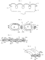
- an inlet manifold M is shown.
- the inlet manifold M includes inlet pipes 10 to be communicated with respective cylinders of an engine, and a flange 11 with bolt holes (not shown).
- the inlet manifold M is attached to a cylinder head through a gasket A by means of the bolts B passing through the bolt holes.
- the gasket A includes a plurality of holes 20 through which air inhaled from the inlet pipes 10 flows to the cylinders, and a plurality of bolt holes 21.
- the bolts B pass through the bolt holes 21 and are fixed to the cylinder head.
- the gasket A is formed of an upper plate A22, a middle plate A23 and a lower plate A24 laminated with each other. Also, a grommet A25 is installed around the bolt holes 21.
- the upper and lower plates A22, A24 are the same and are arranged symmetrically relative to the middle plate A23.
- the upper plate A22 includes holes corresponding to the holes 20, 21, beads A22a formed around the holes 20, and beads A22b formed around the bolt holes 21.
- the beads A22a are compressed to seal around the holes 20.
- the beads A22b are compressed as well, but the beads A22b operate as a space forming member.
- the beads A22b are not used to seal around the bolt holes 21.
- the middle plate A23 includes holes corresponding to the holes 20, 21, and a plurality of corrugations A23a.
- the corrugations A23a operate as a space forming member.
- the lower plate A24 also includes holes corresponding to the holes 20, 21, beads A24a formed around the holes 20, and beads A24b formed around the bolt holes 21.
- the beads A24a seal around the hole 20, but the beads A24b operate as a space forming member.
- the grommet A25 has upper and lower flanges A25a, A25b, and a curved portion A25c to define the bolt hole 21.
- the upper flange A25a is located above the upper plate A22, while the lower flange A25b is located under the lower plate A24.
- the grommet A25 operates as a spacer for the gasket A.
- the distance of the grommet A25 between the outer surfaces of the upper and lower flanges A25a, A25b is shorter than the distance between the outer surfaces of the upper and lower plates A22, A24 before the gasket A is compressed.
- the grommet A25 is not compressed when the gasket is tightened.
- the distance between the upper and lower plates A22, A24 is compressed to the thickness or distance of the grommet A25. Therefore, the beads A22a, A24a are compressed to seal around the hole 20.
- the beads A22b, A24b are compressed as well, but the beads A22b, A24b need not seal around the hole 21.
- the corrugations A23a are slightly compressed when the gasket A is tightened, but the corrugations A23a form spaces A26 between the plates.
- outer peripheries of the plates A22, A23, A24 are arranged substantially parallel to each other, and the spaces A26 between the plates open outwardly. Even if the gasket A is tightened, the spaces 26 between the plates are substantially maintained throughout the gasket A.
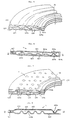
- Fig. 6 shows a second embodiment B of a metal gasket of the invention.
- the gasket B includes an upper plate B22, a middle plate B23 and a lower plate B24.
- the upper plate B22 is made of a heat insulating material, such as zirconium oxide, silicon nitride and the like.
- the middle plate B23 includes corrugations B23a, a bead B23b around the hole 20, and a bead B23c around the hole 21.
- the corrugations B23a operate to separate the upper and lower plates B22, B24 with spaces therebetween.
- the bead B23b seals around the hole 20 when the gasket B is compressed, and the bead B23c operates as a space forming member.
- the lower plate B24 includes a curved portion B24a around the hole 20, and a flange B24b situated above the upper plate B22. Since the curved portion B24a is formed around the hole 20, fluid passing through the hole 20 does not enter the spaces between the plates.
- two ring members B27 are attached onto an inner portion of the lower plate B24 around the hole 21.
- the ring members B27 are fixed to the upper and lower plates B22, B24 by spot welding. The ring members B27 are not compressed when the gasket B is tightened.
- the gasket B When the gasket B is tightened, the plates are compressed to the thickness at the ring members B27. Therefore, the bead B23b is compressed and seals around the hole 20. Spaces are kept inside the plates by means of the corrugations B23a and the bead B23c, so that heat is radiated by the plates, and heat transmission between the cylinder head and the inlet manifold is reduced.
- the gasket B operates as in the gasket A.
- Fig. 7 shows a third embodiment C of a metal gasket of the invention.
- the gasket C includes an upper plate C22 with a bead C22a, a middle plate C23, and a lower plate C24 with a bead C24a, as in the gasket A.
- the middle plate C23 is provided with a plurality of small projections C23a extending upwardly and downwardly therefrom instead of the corrugations A23a of the gasket A.
- the rest of the structure of the gasket C is the same as the gasket A.
- gasket C since the small projections C23a are formed to provide spaces C26 between the plates, insulating air layer is formed.
- the gasket C operates as in the gasket A.
- Fig. 8 shows a fourth embodiment D of a metal gasket of the invention.
- the gasket D is formed of two plates, i.e. upper plate D22 and lower plate D24, and a ring member D27 around a hole 21.
- the upper plate D22 includes a bead D22a around a hole 20 for sealing therearound, and the lower plate D24 includes corrugations D24a to form a space D26 between the upper and lower plates D22, D24.
- a heat insulating layer D28 is laminated onto the upper plate D22.
- the heat insulating layer D28 may be made of ceramics, NBR gum or fluorine gum.
- the heat insulating layer D28 is formed on the upper plate D22.
- the heat insulating layer D28 may be formed on both surfaces of the plate D22 or on the lower plate D24.
- a desired heat insulating material may be applied onto the plates entirely or partly.
- the gasket when the gasket is tightened, the gasket is compressed up to a thickness defined by spacers, by which sealing means is compressed to seal around a hole. Since space forming means is provided in the gasket, the plates do not abut against each other, and spaces are formed between the plates. Therefore, heat is partly insulated by the gasket, and heat transmission between the engine parts is reduced.
Abstract
Description
- The present invention relates to a metal gasket with low heat transmission. In particular, heat transmission between engine parts is reduced by the gasket of the invention.
- A metal gasket, such as a steel laminate gasket, has been known and used for sealing between engine parts, such as between a cylinder block and a cylinder head and between a cylinder head and an exhaust manifold.
- The steel laminate gasket comprises at least two metal plates and sealing devices, such as beads, formed around holes to be sealed. One or more metal plate may be installed between the metal plates. When the steel laminate gasket is tightened, the beads are compressed and all the plates substantially abut against each other without space therebetween.
- Accordingly, although the steel laminate gasket can securely seal between the engine parts, heat between the engine parts is substantially completely transmitted through the gasket.
- In an engine equipped with an inlet manifold, pressure and temperature applied to the inlet manifold are relatively low when comparing with those applied to an exhaust manifold. Therefore, a conventional gasket made of asbestos, glass fibers, carbon fibers or other gasket materials has been used as an inlet manifold gasket.
- Recently, an engine is required to provide high power in small size. Temperature in the new engine becomes high when operated, but heat does not generally affect engine parts while the engine is operated because the engine is cooled. However, when the engine is stopped, heat by the engine affects the engine parts, such as the inlet manifold, and may cause trouble in starting an engine with a fuel injection system, which is attached to the inlet manifold.
- Namely, in case a car is stopped for a while to allow the engine to cool down, heat by the engine does not affect the fuel injection system attached to the inlet manifold. However, in case a car is started within a short period of time after the car was stopped, heat from the cylinder head is transferred to the inlet manifold through a gasket and causes vapor lock at the fuel injection system. Namely, the engine may not be started until the engine is cooled.
- In order to reduce heat transmission from the engine to the inlet manifold, a gasket with heat insulating characteristics is required. The conventional gasket made of asbestos or a conventional gasket material is low in heat transmission, but such material is not good as a gasket with heat insulating characteristics.
- A conventional steel laminate gasket has high heat transmission characteristics, but heat is transmitted instantly from the cylinder head to the inlet manifold through the steel laminate gasket. Therefore, the conventional steel laminate gasket can not be used as a gasket for the inlet manifold.
- Accordingly, one object of the present invention is to provide a metal gasket, which can reduce heat transmission between two engine parts.
- Another object of the invention is to provide a metal gasket as stated above, which can radiate heat from the engine parts.
- A further object of the invention is to provide a metal gasket as stated above, wherein two engine parts can be sealed effectively.
- A still further object of the invention is to provide a metal gasket as stated above, which can be easily and economically manufactured.
- Further objects and advantages of the invention will be apparent from the following description of the invention.
- In accordance with the invention, a metal gasket is installed between two engine parts with at least one hole to be sealed. The gasket can securely seal between the two engine parts while reducing heat transmission therebetween. Namely, although one of the engine parts is heated, such heat is not directly transmitted to the other of the engine parts. Heat is partly radiated by the metal gasket.
- The gasket is basically formed of two metal plates extending substantially throughout the entire area of the gasket. The metal plates are provided with first holes corresponding to the holes of the engine parts to be sealed, and bolt holes for attaching the metal plates to the engine parts. The gasket also includes sealing means formed around the first holes, and space forming means formed on at least one of the metal plates to keep the metal plates separated from each other.
- Spacers are formed around the bolt holes. The thickness of the spacer is less than the thickness of the sealing means before the gasket is compressed. Therefore, when the gasket is tightened at the spacers, the sealing means is compressed to seal around the hole of the engine parts, but the two metal plates do not closely abut against each other. The space forming means forms space between the two metal plates to thereby reduce heat transmission between the two engine parts.
- Namely, when the gasket is tightened at the spacers, the sealing means is compressed to seal around the holes of the engine parts. However, since the two metal plates do not closely abut against each other by the space forming means, heat is not directly transmitted through the metal plates, and heat is partly radiated through the space.
- The space forming means may be a plurality of projections formed on at least one of the metal plates. The projections may be intermittent projections or continuous projections such as beads. Also, the sealing means may be a bead formed on at least one of the metal plates around the first holes.
- A heat insulating layer may be formed on at least one of the metal plates. Also, a heat insulating plate or other metal plate may be laminated further with the metal plates.
-
- Fig. 1 is an explanatory side view of an inlet manifold;
- Fig. 2 is a partly cut plan view of a first embodiment of a metal gasket of the present invention;
- Fig. 3 is an enlarged section view taken along a line 3-3 in Fig. 2;
- Fig. 4 is an enlarged section view taken along a line 4-4 in Fig. 2;
- Fig. 5 is an enlarged section view taken along a ling 5-5 in Fig. 2;
- Fig. 6 is a section view, similar to Fig. 3, of a second embodiment of a metal gasket of the invention;
- Fig. 7 is a perspective section view, similar to Fig. 5, of a third embodiment of a metal gasket of the invention; and
- Fig. 8 is a section view, similar to Fig. 3, of a fourth embodiment of a metal gasket of the invention.
- Referring to Fig. 1, an inlet manifold M is shown. The inlet manifold M includes
inlet pipes 10 to be communicated with respective cylinders of an engine, and aflange 11 with bolt holes (not shown). The inlet manifold M is attached to a cylinder head through a gasket A by means of the bolts B passing through the bolt holes. - As shown in Figs. 2-5, the gasket A includes a plurality of
holes 20 through which air inhaled from theinlet pipes 10 flows to the cylinders, and a plurality ofbolt holes 21. The bolts B pass through thebolt holes 21 and are fixed to the cylinder head. - The gasket A is formed of an upper plate A22, a middle plate A23 and a lower plate A24 laminated with each other. Also, a grommet A25 is installed around the
bolt holes 21. The upper and lower plates A22, A24 are the same and are arranged symmetrically relative to the middle plate A23. - The upper plate A22 includes holes corresponding to the
holes holes 20, and beads A22b formed around thebolt holes 21. When the gasket A is tightened, the beads A22a are compressed to seal around theholes 20. The beads A22b are compressed as well, but the beads A22b operate as a space forming member. The beads A22b are not used to seal around the bolt holes 21. - The middle plate A23 includes holes corresponding to the
holes - The lower plate A24 also includes holes corresponding to the
holes holes 20, and beads A24b formed around the bolt holes 21. The beads A24a seal around thehole 20, but the beads A24b operate as a space forming member. - The grommet A25 has upper and lower flanges A25a, A25b, and a curved portion A25c to define the
bolt hole 21. The upper flange A25a is located above the upper plate A22, while the lower flange A25b is located under the lower plate A24. The grommet A25 operates as a spacer for the gasket A. - The distance of the grommet A25 between the outer surfaces of the upper and lower flanges A25a, A25b is shorter than the distance between the outer surfaces of the upper and lower plates A22, A24 before the gasket A is compressed. The grommet A25 is not compressed when the gasket is tightened.
- When the gasket A is tightened, the distance between the upper and lower plates A22, A24 is compressed to the thickness or distance of the grommet A25. Therefore, the beads A22a, A24a are compressed to seal around the
hole 20. The beads A22b, A24b are compressed as well, but the beads A22b, A24b need not seal around thehole 21. The corrugations A23a are slightly compressed when the gasket A is tightened, but the corrugations A23a form spaces A26 between the plates. - Namely, when the gasket A is tightened, the portions around the bolt holes 21 and the
holes 20 are tightly compressed, but the spaces A26 are formed between the plates. The plates A22, A23, A24 do not closely abut against each other. - As shown in Figs. 4 and 5, outer peripheries of the plates A22, A23, A24 are arranged substantially parallel to each other, and the spaces A26 between the plates open outwardly. Even if the gasket A is tightened, the spaces 26 between the plates are substantially maintained throughout the gasket A.
- Accordingly, in case the cylinder head is heated, heat is isolated by the spaces 26 of the gasket A and is not transferred. Heat at the cylinder head is not directly transmitted to the inlet manifold. Therefore, in case an engine is stopped, the inlet manifold is not heated extremely by heat of the cylinder head. Even if the engine is started shortly after the engine was stopped, vapor lock does not occur at the fuel injection system.
- Fig. 6 shows a second embodiment B of a metal gasket of the invention. The gasket B includes an upper plate B22, a middle plate B23 and a lower plate B24. The upper plate B22 is made of a heat insulating material, such as zirconium oxide, silicon nitride and the like.
- The middle plate B23 includes corrugations B23a, a bead B23b around the
hole 20, and a bead B23c around thehole 21. The corrugations B23a operate to separate the upper and lower plates B22, B24 with spaces therebetween. The bead B23b seals around thehole 20 when the gasket B is compressed, and the bead B23c operates as a space forming member. - The lower plate B24 includes a curved portion B24a around the
hole 20, and a flange B24b situated above the upper plate B22. Since the curved portion B24a is formed around thehole 20, fluid passing through thehole 20 does not enter the spaces between the plates. - In the gasket B, two ring members B27 are attached onto an inner portion of the lower plate B24 around the
hole 21. The ring members B27 are fixed to the upper and lower plates B22, B24 by spot welding. The ring members B27 are not compressed when the gasket B is tightened. - When the gasket B is tightened, the plates are compressed to the thickness at the ring members B27. Therefore, the bead B23b is compressed and seals around the
hole 20. Spaces are kept inside the plates by means of the corrugations B23a and the bead B23c, so that heat is radiated by the plates, and heat transmission between the cylinder head and the inlet manifold is reduced. The gasket B operates as in the gasket A. - Fig. 7 shows a third embodiment C of a metal gasket of the invention. The gasket C includes an upper plate C22 with a bead C22a, a middle plate C23, and a lower plate C24 with a bead C24a, as in the gasket A.
- In the gasket C, however, the middle plate C23 is provided with a plurality of small projections C23a extending upwardly and downwardly therefrom instead of the corrugations A23a of the gasket A. The rest of the structure of the gasket C is the same as the gasket A.
- In the gasket C, since the small projections C23a are formed to provide spaces C26 between the plates, insulating air layer is formed. The gasket C operates as in the gasket A.
- Fig. 8 shows a fourth embodiment D of a metal gasket of the invention. The gasket D is formed of two plates, i.e. upper plate D22 and lower plate D24, and a ring member D27 around a
hole 21. - The upper plate D22 includes a bead D22a around a
hole 20 for sealing therearound, and the lower plate D24 includes corrugations D24a to form a space D26 between the upper and lower plates D22, D24. Also, a heat insulating layer D28 is laminated onto the upper plate D22. The heat insulating layer D28 may be made of ceramics, NBR gum or fluorine gum. - In the gasket D, the heat insulating layer D28 is formed on the upper plate D22. However, the heat insulating layer D28 may be formed on both surfaces of the plate D22 or on the lower plate D24. A desired heat insulating material may be applied onto the plates entirely or partly.
- When the gasket D is tightened, the bead D22a seals around the
hole 20, and the corrugations D24a form spaces between theplates D22, D24, as in the gasket A. Since the heat insulating layer D28 is formed on the upper plate D22, heat insulating property of the gasket D is improved. - In the present invention, when the gasket is tightened, the gasket is compressed up to a thickness defined by spacers, by which sealing means is compressed to seal around a hole. Since space forming means is provided in the gasket, the plates do not abut against each other, and spaces are formed between the plates. Therefore, heat is partly insulated by the gasket, and heat transmission between the engine parts is reduced.
- While the invention has been explained with reference to the specific embodiments of the invention, the explanation is illustrative and the invention is limited only by the appended claims.
Claims (10)
- A metal gasket for reducing heat transmission between two engine parts with at least one hole to be sealed, comprising,
at least two plates extending substantially throughout the entire area of the gasket and having first holes corresponding to the hole of the engine parts to be sealed and bolt holes for attaching the plates to the engine parts,
sealing means formed around the first holes, said sealing means, when the gasket is tightened, being compressed to seal around the hole of the engine parts,
space forming means formed on at least one of the plates to provide space between the plates,
spacers formed around the bolt holes, said spacer having a thickness less than a thickness of the sealing means before the gasket is compressed so that when the gasket is tightened at the spacers, the sealing means is compressed to seal around the hole of the engine parts while the two plates do not closely abut against each other and provide spaces between the plates by the space forming means to thereby reduce heat transmission between the two engine parts by means of the gasket. - A metal gasket according to claim 1, wherein said space forming means is a plurality of projections formed on at least one of the plates.
- A metal gasket according to claim 2, wherein said projections are beads.
- A metal gasket according to claim 2, wherein said sealing means is at least one bead formed on one of the plates around the first hole.
- A metal gasket according to claim 4, further comprising an outer periphery having spaces between the plates to radiate heat from the gasket through the spaces.
- A metal gasket according to claim 5, further comprising a heat insulating layer formed on at least one of the plates.
- A metal gasket according to claim 5, further comprising an additional plate laminated on the two plates, said space forming means being formed on a middle plate of the gasket.
- A metal gasket according to claim 7, wherein said additional plate is a heat insulating plate.
- A metal gasket according to claim 7, wherein said additional plate is located under the two plates and includes a curved portion formed around the first hole and a flange located outside a top plate so that fluid does not enter between the plates.
- A metal gasket according to claim 7, wherein said spacers are grommets formed around the bolt holes.
Applications Claiming Priority (2)
| Application Number | Priority Date | Filing Date | Title |
|---|---|---|---|
| JP1990083094U JP2521155Y2 (en) | 1990-08-07 | 1990-08-07 | Insulating metal laminated gasket |
| JP83094/90U | 1990-08-07 |
Publications (2)
| Publication Number | Publication Date |
|---|---|
| EP0470790A1 true EP0470790A1 (en) | 1992-02-12 |
| EP0470790B1 EP0470790B1 (en) | 1995-04-12 |
Family
ID=13792594
Family Applications (1)
| Application Number | Title | Priority Date | Filing Date |
|---|---|---|---|
| EP91307177A Expired - Lifetime EP0470790B1 (en) | 1990-08-07 | 1991-08-05 | Metal gasket with low heat transmission |
Country Status (5)
| Country | Link |
|---|---|
| US (2) | US5232229A (en) |
| EP (1) | EP0470790B1 (en) |
| JP (1) | JP2521155Y2 (en) |
| DE (1) | DE69108814T2 (en) |
| ES (1) | ES2070433T3 (en) |
Cited By (9)
| Publication number | Priority date | Publication date | Assignee | Title |
|---|---|---|---|---|
| WO2001096768A1 (en) * | 2000-06-15 | 2001-12-20 | Reinz-Dichtungs-Gmbh & Co. Kg | Flat gasket and method for the production thereof |
| EP1298365A2 (en) | 2001-09-29 | 2003-04-02 | ElringKlinger AG | Metallic cylinder head gasket |
| EP1298364A2 (en) | 2001-09-29 | 2003-04-02 | ElringKlinger AG | Metallic cylinder head gasket |
| US6769696B2 (en) | 2001-09-29 | 2004-08-03 | Elringklinger Ag | At least substantially metallic cylinder head gasket |
| DE102004040516A1 (en) * | 2004-08-20 | 2006-02-23 | Reinz-Dichtungs-Gmbh | Metallic flat gasket with shortened gasket layer |
| EP1679457A1 (en) * | 2000-06-15 | 2006-07-12 | Reinz-Dichtungs-Gmbh | Flat gasket and method for the production thereof |
| US7527269B2 (en) * | 2004-09-10 | 2009-05-05 | Elringklinger Ag | Cylinder head gasket having deformation delimiting devices radially inside and outside sealing bead |
| DE202009002162U1 (en) | 2009-02-14 | 2009-06-18 | Reinz-Dichtungs-Gmbh | Metallic flat gasket |
| US9638089B2 (en) | 2014-01-23 | 2017-05-02 | Dana Automotive Systems Group, Llc | Gasket assembly |
Families Citing this family (33)
| Publication number | Priority date | Publication date | Assignee | Title |
|---|---|---|---|---|
| US5375856A (en) * | 1992-01-22 | 1994-12-27 | Ishikawa Gasket Co., Ltd. | Protecting member for a gasket |
| JP2522419Y2 (en) * | 1993-12-16 | 1997-01-16 | 石川ガスケット株式会社 | Exhaust gas seal device |
| JP3129626B2 (en) * | 1995-02-06 | 2001-01-31 | 日本ガスケット株式会社 | Metal gasket |
| DE19520268A1 (en) * | 1995-06-02 | 1996-12-05 | Abb Management Ag | Seal for contact faces of static elements |
| JPH09210207A (en) * | 1996-02-01 | 1997-08-12 | Ishikawa Gasket Kk | Metallic laminate-type gasket |
| JP3698283B2 (en) * | 1996-10-04 | 2005-09-21 | 大豊工業株式会社 | Cylinder head gasket |
| DE19719328C1 (en) * | 1997-05-08 | 1998-06-25 | Elringklinger Gmbh | Metallic cylinder-head seal for internal combustion engine |
| US5924701A (en) * | 1997-09-08 | 1999-07-20 | Dana Corporation | Multi-layered steel, dual-purpose intake/exhaust gasket |
| US6036195A (en) * | 1998-03-09 | 2000-03-14 | Ishikawa Gasket Co., Ltd. | Metal gasket with double beads |
| JP3363781B2 (en) * | 1998-03-18 | 2003-01-08 | 石川ガスケット株式会社 | Metal plate gasket with multiple seals |
| JP4032270B2 (en) * | 1998-09-18 | 2008-01-16 | 大豊工業株式会社 | Cylinder head gasket |
| JP3460819B2 (en) * | 2000-11-09 | 2003-10-27 | 石川ガスケット株式会社 | Head gasket |
| DE20021017U1 (en) * | 2000-12-12 | 2001-02-22 | Reinz Dichtungs Gmbh U Co Kg | Cylinder head gasket |
| FR2851186B1 (en) * | 2003-02-17 | 2006-02-24 | Meillor Sa | METHOD AND DEVICE FOR LINKING BY WELDING AT LEAST TWO METAL SHEETS AND JOINTS OBTAINED |
| JP3769549B2 (en) * | 2003-03-26 | 2006-04-26 | 石川ガスケット株式会社 | Metal gasket |
| JP4155357B2 (en) * | 2004-02-04 | 2008-09-24 | 石川ガスケット株式会社 | Cylinder head gasket |
| FR2875570B1 (en) * | 2004-09-21 | 2007-02-16 | Meillor Sa Sa | JOINT COMPRISING AT LEAST ONE RIB INCORPORATING A CRUSHING LIMITER |
| JP2006144808A (en) * | 2004-11-16 | 2006-06-08 | Ishikawa Gasket Co Ltd | Metal gasket |
| JP2007139177A (en) * | 2005-10-20 | 2007-06-07 | Japan Metal Gasket Co Ltd | Gasket |
| EP1985896B1 (en) * | 2007-04-24 | 2012-12-12 | REINZ-Dichtungs-GmbH | Metal flat gasket |
| KR100845273B1 (en) * | 2006-12-28 | 2008-07-09 | 동아공업 주식회사 | Gasket with inner plate having embossing |
| US20080277883A1 (en) * | 2007-05-10 | 2008-11-13 | Corey Hager | Multilayered gasket for internal combustion engine |
| EP2325529A4 (en) * | 2008-09-18 | 2016-03-16 | Nippon Gasket Kk | Cylinder head gasket |
| DE102009030559B4 (en) * | 2009-06-25 | 2012-11-22 | Federal-Mogul Sealing Systems Gmbh | Flat gasket with a full bead |
| US8128098B2 (en) * | 2009-10-22 | 2012-03-06 | Dana Automotive Systems Group, Llc | Multi-layered gasket |
| US20110204583A1 (en) * | 2010-02-24 | 2011-08-25 | Freudenberg-Nok General Partnership | Gasket Having Dual Bead Orientation On Rigid Carrier With Adjoining Gasket Material |
| DE102010049958B4 (en) * | 2010-10-28 | 2012-07-12 | Reinz-Dichtungs-Gmbh | Multi-layer seal and its use |
| CN103946531B (en) * | 2011-12-01 | 2017-10-03 | 博格华纳公司 | Metal beading is padded |
| WO2014033876A1 (en) * | 2012-08-30 | 2014-03-06 | ナブテスコ株式会社 | Hermetically sealed artificial leg |
| US20150069718A1 (en) * | 2013-09-12 | 2015-03-12 | Federal-Mogul Corporation | Metal gasket assembly |
| US10522852B2 (en) * | 2017-02-06 | 2019-12-31 | Gm Global Technology Operations Llc. | Reinforcement structure for bead seal in a plate assembly |
| FR3090063B1 (en) * | 2018-12-14 | 2021-03-19 | Commissariat Energie Atomique | METAL SEAL WITH AN EXTERNAL TEXTURED SEALING LAYER |
| US11703013B1 (en) * | 2022-03-03 | 2023-07-18 | Caterpillar Inc. | Engine head gasket having anti-preignition wrap and method of making same |
Citations (3)
| Publication number | Priority date | Publication date | Assignee | Title |
|---|---|---|---|---|
| US4799695A (en) * | 1982-05-17 | 1989-01-24 | Nihon Metal Gasket Kabushiki Kaisha | Metallic gasket |
| EP0306766A2 (en) * | 1987-09-05 | 1989-03-15 | Nihon Metal Gasket Kabushiki Kaisha | Laminated metallic gasket |
| US4869516A (en) * | 1984-12-14 | 1989-09-26 | Ishikawa Gasket Co., Ltd. | Steel laminate gaskets |
Family Cites Families (16)
| Publication number | Priority date | Publication date | Assignee | Title |
|---|---|---|---|---|
| US1782087A (en) * | 1926-05-07 | 1930-11-18 | Mccord Radiator & Mfg Co | Gasket |
| US1840147A (en) * | 1928-02-08 | 1932-01-05 | Chrysler Corp | Gasket |
| US4196913A (en) * | 1976-07-14 | 1980-04-08 | Kosaku Ueda | Gaskets |
| GB1549200A (en) * | 1976-07-23 | 1979-08-01 | Engineering Components Ltd | Gaskets |
| US4163950A (en) * | 1978-03-01 | 1979-08-07 | Tektronix, Inc. | Isolating differential amplifier |
| JPS60180867U (en) * | 1984-05-12 | 1985-11-30 | 株式会社 福田パツキング製作所 | Metal plate laminate gasket |
| JPS6188075A (en) * | 1984-10-05 | 1986-05-06 | Nippon Metal Gasket Kk | Method and device of preventing occurrence of heat damage by means of metallic gasket |
| JPS61169647A (en) * | 1985-01-21 | 1986-07-31 | Yanmar Diesel Engine Co Ltd | Gasket of laminate structure |
| DE3531551A1 (en) * | 1985-09-04 | 1987-03-12 | Lechler Elring Dichtungswerke | COMBINED INTAKE EXHAUST GASKET FOR COMBUSTION ENGINES |
| JPH0622135Y2 (en) * | 1986-01-13 | 1994-06-08 | 石川ガスケット株式会社 | Metal stack type manifold gasket |
| JPH0416027Y2 (en) * | 1986-06-26 | 1992-04-10 | ||
| JPS63246571A (en) * | 1987-03-31 | 1988-10-13 | Nippon Metal Gasket Kk | Laminated metal gasket |
| JPH0433492Y2 (en) * | 1987-04-11 | 1992-08-11 | ||
| JPH0285644A (en) * | 1988-09-22 | 1990-03-27 | Matsushita Electric Ind Co Ltd | Hot water storage tank |
| JPH0449410Y2 (en) * | 1988-10-29 | 1992-11-20 | ||
| JP2921941B2 (en) * | 1990-08-13 | 1999-07-19 | 日本ガスケット株式会社 | Metal gasket for manifold |
-
1990
- 1990-08-07 JP JP1990083094U patent/JP2521155Y2/en not_active Expired - Lifetime
-
1991
- 1991-07-30 US US07/736,965 patent/US5232229A/en not_active Expired - Lifetime
- 1991-08-05 ES ES91307177T patent/ES2070433T3/en not_active Expired - Lifetime
- 1991-08-05 DE DE69108814T patent/DE69108814T2/en not_active Expired - Fee Related
- 1991-08-05 EP EP91307177A patent/EP0470790B1/en not_active Expired - Lifetime
-
1993
- 1993-04-29 US US08/053,547 patent/US5306024A/en not_active Expired - Lifetime
Patent Citations (4)
| Publication number | Priority date | Publication date | Assignee | Title |
|---|---|---|---|---|
| US4799695A (en) * | 1982-05-17 | 1989-01-24 | Nihon Metal Gasket Kabushiki Kaisha | Metallic gasket |
| US4799695B1 (en) * | 1982-05-17 | 1991-10-15 | Nihon Metal Gasket | |
| US4869516A (en) * | 1984-12-14 | 1989-09-26 | Ishikawa Gasket Co., Ltd. | Steel laminate gaskets |
| EP0306766A2 (en) * | 1987-09-05 | 1989-03-15 | Nihon Metal Gasket Kabushiki Kaisha | Laminated metallic gasket |
Non-Patent Citations (1)
| Title |
|---|
| PATENT ABSTRACTS OF JAPAN, vol. 10, no. 265 (M-515)[2321], 10th September 1986; & JP-A-61 88 075 (NIPPON METAL GASKET) 06-05-1986 * |
Cited By (16)
| Publication number | Priority date | Publication date | Assignee | Title |
|---|---|---|---|---|
| US7000924B2 (en) | 2000-06-15 | 2006-02-21 | Dana Corporation | Flat gasket and method for the production thereof |
| DE10060872B4 (en) * | 2000-06-15 | 2012-11-15 | Reinz-Dichtungs-Gmbh | gasket |
| US8162326B2 (en) | 2000-06-15 | 2012-04-24 | Dana Automotive Systems Group, Llc | Flat gasket and method for the production thereof |
| EP2020540A1 (en) * | 2000-06-15 | 2009-02-04 | Reinz-Dichtungs-Gmbh | Flat gasket and its manufacturing method |
| WO2001096768A1 (en) * | 2000-06-15 | 2001-12-20 | Reinz-Dichtungs-Gmbh & Co. Kg | Flat gasket and method for the production thereof |
| EP1679457A1 (en) * | 2000-06-15 | 2006-07-12 | Reinz-Dichtungs-Gmbh | Flat gasket and method for the production thereof |
| US6769696B2 (en) | 2001-09-29 | 2004-08-03 | Elringklinger Ag | At least substantially metallic cylinder head gasket |
| US6814357B2 (en) | 2001-09-29 | 2004-11-09 | Elringklinger Ag | At least substantially metallic cylinder head gasket |
| EP1298364A3 (en) * | 2001-09-29 | 2004-03-24 | ElringKlinger AG | Metallic cylinder head gasket |
| US7490835B2 (en) | 2001-09-29 | 2009-02-17 | Elringklinger Ag | At least substantially metallic cylinder head gasket |
| EP1298364A2 (en) | 2001-09-29 | 2003-04-02 | ElringKlinger AG | Metallic cylinder head gasket |
| EP1298365A2 (en) | 2001-09-29 | 2003-04-02 | ElringKlinger AG | Metallic cylinder head gasket |
| DE102004040516A1 (en) * | 2004-08-20 | 2006-02-23 | Reinz-Dichtungs-Gmbh | Metallic flat gasket with shortened gasket layer |
| US7527269B2 (en) * | 2004-09-10 | 2009-05-05 | Elringklinger Ag | Cylinder head gasket having deformation delimiting devices radially inside and outside sealing bead |
| DE202009002162U1 (en) | 2009-02-14 | 2009-06-18 | Reinz-Dichtungs-Gmbh | Metallic flat gasket |
| US9638089B2 (en) | 2014-01-23 | 2017-05-02 | Dana Automotive Systems Group, Llc | Gasket assembly |
Also Published As
| Publication number | Publication date |
|---|---|
| EP0470790B1 (en) | 1995-04-12 |
| DE69108814T2 (en) | 1995-08-24 |
| JP2521155Y2 (en) | 1996-12-25 |
| US5306024A (en) | 1994-04-26 |
| JPH0441155U (en) | 1992-04-08 |
| ES2070433T3 (en) | 1995-06-01 |
| DE69108814D1 (en) | 1995-05-18 |
| US5232229A (en) | 1993-08-03 |
Similar Documents
| Publication | Publication Date | Title |
|---|---|---|
| US5232229A (en) | Metal gasket with low heat transmission | |
| EP0987474B1 (en) | Cylinder head gasket | |
| EP0809051B1 (en) | Metal laminate gasket with partial bead section | |
| JP2520352Y2 (en) | Head gasket | |
| EP0430163B1 (en) | Steel laminate gasket with main and auxiliary sealing devices | |
| US5775701A (en) | Exhaust tube gasket for combustion gases | |
| EP0892199B1 (en) | Metal laminate gasket with wide and narrow flange portions | |
| JP2522419Y2 (en) | Exhaust gas seal device | |
| US6318733B1 (en) | Metal laminate gasket with elastic auxiliary sealing member | |
| US5255927A (en) | Metal laminate type cylinder head gasket | |
| US20220307599A1 (en) | Multi-Layer Steel Gasket | |
| JPH06100285B2 (en) | Cylinder / Head / Gasket | |
| JP3457438B2 (en) | Head gasket | |
| JP2787041B2 (en) | Metal laminated gasket | |
| KR0184708B1 (en) | Metal laminate type | |
| JPH0729360U (en) | Metal gasket for manifold | |
| JPH0719343A (en) | Gasket for exhaust manifold | |
| JPH051735Y2 (en) | ||
| JP2580808Y2 (en) | Metal laminated gasket | |
| JPH0721967Y2 (en) | Metal gasket | |
| JPH0536134Y2 (en) | ||
| JPS6321700Y2 (en) | ||
| JPH05280646A (en) | Seal ring for cylinder liner with flange | |
| JPH0611040A (en) | Metallic gasket | |
| JPH037530Y2 (en) |
Legal Events
| Date | Code | Title | Description |
|---|---|---|---|
| PUAI | Public reference made under article 153(3) epc to a published international application that has entered the european phase |
Free format text: ORIGINAL CODE: 0009012 |
|
| AK | Designated contracting states |
Kind code of ref document: A1 Designated state(s): DE ES FR GB IT SE |
|
| 17P | Request for examination filed |
Effective date: 19920108 |
|
| 17Q | First examination report despatched |
Effective date: 19931006 |
|
| GRAA | (expected) grant |
Free format text: ORIGINAL CODE: 0009210 |
|
| AK | Designated contracting states |
Kind code of ref document: B1 Designated state(s): DE ES FR GB IT SE |
|
| ITF | It: translation for a ep patent filed |
Owner name: BUGNION S.P.A. |
|
| REF | Corresponds to: |
Ref document number: 69108814 Country of ref document: DE Date of ref document: 19950518 |
|
| ET | Fr: translation filed | ||
| REG | Reference to a national code |
Ref country code: ES Ref legal event code: FG2A Ref document number: 2070433 Country of ref document: ES Kind code of ref document: T3 |
|
| PLBE | No opposition filed within time limit |
Free format text: ORIGINAL CODE: 0009261 |
|
| STAA | Information on the status of an ep patent application or granted ep patent |
Free format text: STATUS: NO OPPOSITION FILED WITHIN TIME LIMIT |
|
| 26N | No opposition filed | ||
| PGFP | Annual fee paid to national office [announced via postgrant information from national office to epo] |
Ref country code: SE Payment date: 20010807 Year of fee payment: 11 |
|
| PGFP | Annual fee paid to national office [announced via postgrant information from national office to epo] |
Ref country code: ES Payment date: 20010824 Year of fee payment: 11 |
|
| REG | Reference to a national code |
Ref country code: GB Ref legal event code: IF02 |
|
| PG25 | Lapsed in a contracting state [announced via postgrant information from national office to epo] |
Ref country code: SE Free format text: LAPSE BECAUSE OF NON-PAYMENT OF DUE FEES Effective date: 20020806 Ref country code: ES Free format text: LAPSE BECAUSE OF NON-PAYMENT OF DUE FEES Effective date: 20020806 |
|
| EUG | Se: european patent has lapsed | ||
| REG | Reference to a national code |
Ref country code: ES Ref legal event code: FD2A Effective date: 20030912 |
|
| PGFP | Annual fee paid to national office [announced via postgrant information from national office to epo] |
Ref country code: DE Payment date: 20050728 Year of fee payment: 15 |
|
| PGFP | Annual fee paid to national office [announced via postgrant information from national office to epo] |
Ref country code: GB Payment date: 20050803 Year of fee payment: 15 |
|
| PGFP | Annual fee paid to national office [announced via postgrant information from national office to epo] |
Ref country code: FR Payment date: 20050809 Year of fee payment: 15 |
|
| PGFP | Annual fee paid to national office [announced via postgrant information from national office to epo] |
Ref country code: IT Payment date: 20060831 Year of fee payment: 16 |
|
| PG25 | Lapsed in a contracting state [announced via postgrant information from national office to epo] |
Ref country code: DE Free format text: LAPSE BECAUSE OF NON-PAYMENT OF DUE FEES Effective date: 20070301 |
|
| GBPC | Gb: european patent ceased through non-payment of renewal fee |
Effective date: 20060805 |
|
| REG | Reference to a national code |
Ref country code: FR Ref legal event code: ST Effective date: 20070430 |
|
| PG25 | Lapsed in a contracting state [announced via postgrant information from national office to epo] |
Ref country code: GB Free format text: LAPSE BECAUSE OF NON-PAYMENT OF DUE FEES Effective date: 20060805 |
|
| PG25 | Lapsed in a contracting state [announced via postgrant information from national office to epo] |
Ref country code: FR Free format text: LAPSE BECAUSE OF NON-PAYMENT OF DUE FEES Effective date: 20060831 |
|
| PG25 | Lapsed in a contracting state [announced via postgrant information from national office to epo] |
Ref country code: IT Free format text: LAPSE BECAUSE OF NON-PAYMENT OF DUE FEES Effective date: 20070805 |