EP0470195B1 - Procede et arrangement pour controler la tension d'une lame de scie a ruban - Google Patents
Procede et arrangement pour controler la tension d'une lame de scie a ruban Download PDFInfo
- Publication number
- EP0470195B1 EP0470195B1 EP90908098A EP90908098A EP0470195B1 EP 0470195 B1 EP0470195 B1 EP 0470195B1 EP 90908098 A EP90908098 A EP 90908098A EP 90908098 A EP90908098 A EP 90908098A EP 0470195 B1 EP0470195 B1 EP 0470195B1
- Authority
- EP
- European Patent Office
- Prior art keywords
- blading
- tension
- sawblading
- parameters
- microprocessor
- Prior art date
- Legal status (The legal status is an assumption and is not a legal conclusion. Google has not performed a legal analysis and makes no representation as to the accuracy of the status listed.)
- Expired - Lifetime
Links
Images
Classifications
-
- B—PERFORMING OPERATIONS; TRANSPORTING
- B23—MACHINE TOOLS; METAL-WORKING NOT OTHERWISE PROVIDED FOR
- B23D—PLANING; SLOTTING; SHEARING; BROACHING; SAWING; FILING; SCRAPING; LIKE OPERATIONS FOR WORKING METAL BY REMOVING MATERIAL, NOT OTHERWISE PROVIDED FOR
- B23D59/00—Accessories specially designed for sawing machines or sawing devices
- B23D59/001—Measuring or control devices, e.g. for automatic control of work feed pressure on band saw blade
- B23D59/002—Measuring or control devices, e.g. for automatic control of work feed pressure on band saw blade for the position of the saw blade
-
- B—PERFORMING OPERATIONS; TRANSPORTING
- B23—MACHINE TOOLS; METAL-WORKING NOT OTHERWISE PROVIDED FOR
- B23D—PLANING; SLOTTING; SHEARING; BROACHING; SAWING; FILING; SCRAPING; LIKE OPERATIONS FOR WORKING METAL BY REMOVING MATERIAL, NOT OTHERWISE PROVIDED FOR
- B23D59/00—Accessories specially designed for sawing machines or sawing devices
- B23D59/008—Accessories specially designed for sawing machines or sawing devices comprising computers
Definitions
- the present invention relates to a method of controlling the tension of the sawblading of a bandsaw with the aid of an electrically controllable blade-tensioning device by means of which the sawblading can be stretched so as to adjust the blading to a desired tension.
- the invention also relates to a device for carrying out the method.
- the sawblading When sawing timber into planks and boards with the aid of bandsaws, the sawblading is normally set to saw over-dimensioned pieces of timber in order to compensate for inaccuracies occurring in the actual sawing operation.
- Sawing can be achieved with a high degree of precision, provided that the teeth of the sawblading are sharp, deviations in accuracy will occur as the sharpness of the teeth decreases.
- the sawblading is normally tensioned so as to be flexible, wherewith endeavours are made, inter alia, to reduce the aforesaid deviations, by lowering the infeed speed and therewith reduce the forces transmitted through the teeth on the sawblading during a sawing operation.
- JP-A-5919629 shows a method and device for correcting cutting warp in band saw machine, in which when the warp grows to a certain allowable limit, mechanical means are able to provide a correction of the tension of the blade.
- no micro processor is used and only one parameter is taken into consideration for correction.
- a prime object of the present invention is to increase sawing accuracy while retaining a desired high infeed speed, and to maintain or prolong the useful life of a sawblading, by optimizing blade-tension with each sawing occasion.
- the saw is equipped with a sawblading tensioning arrangement whose power output can be controlled in a rational manner with the aid of electronic pulses.
- Present day micro processors can be used to control proportionally both the gas pressure and hydraulic pressure of known blade-tensioning devices, for instance devices of the kind described and illustrated in Swedish Patent Specification 7312757-3 and in WO 88/03850.
- Stresses in the saw blade or blading are mainly in the form of the tensile stress created by the tension force in the cross-section of the saw blade and by the bending tension occurring as the blading bends around the saw pulleys or wheels. In addition to these stresses, stresses are also created in the blading in conjunction with sharpening the teeth by grinding.
- the sawblading is also subjected to external forces, such as to the effect of the cutting force on the tips of the sawteeth, to the effects of thermal loads and vibrations, and to the effects of torsional and lateral loads caused by the blading itself or because the workpiece moves laterally.
- the following measures are examples of those measures which can be taken for the purpose of achieving optimum blading-tension values and of improving sawing accuracy.
- the specific blading-tension can be calculated and used for control purposes, on the basis of a sensed cross-sectional area of the blading which is changed inter alia each time the sawblading is ground, and on the basis of the tensioning force in the blading.
- Contact-less inductive sensors can be used to detect momentary disturbances in or deviations from the intended movement path of the blading caused, for instance, by heating of the blading, vibrations generated therein or lateral loads thereon, the signals from said sensors being registered and utilized to initiate increased tensioning of the sawblading. Variations in the pressure exerted by the sawblading on the blading guides can also be sensed and recorded, for the same reason.
- This can be monitored with the aid of known image processing apparatus constructed to produce signals corresponding to deviations from an imaginary saw cut.
- this will enable the saw to be operated at relatively low blading-tension provided that the sawblading is sharp, among other things in order to avoid unnecessary loading of the sawblading, this tension being gradually increased in a manner to maintain sawing accuracy as the sharpness of the sawteeth decreases.
- Sensing and calculating devices intended, inter alia, for sensing and calculating the aforesaid parameters can be employed to achieve substantially optimum blading-tension with each sawing operation, wherein attention is paid, inter alia, to the specific tension in the sawblading, the sharpness of the sawteeth, the hardness of the wood being sawn, etc.
- a method of the kind described in the opening paragraph is mainly characterized by the steps of determining during a sawing operation, with the aid of automatically operating means, whether the blading-tension is optimum or not; determining said tension by sensing and determining at least two mutually different parameters drawn from specific blading-tension, disturbances in the pattern of blading movement, saw-cut linearity; processing electrical signals corresponding to said parameters in a microprocessor, when deviations from parameter limit values programmed in the microprocessor or fluctuations in the parameters are established, transmitting control signals from said microprocessor to the blading-tensioning device such as to adjust the blading-tension; determining by means of said automatically operating means when the blading-tension is optimum; and terminating the control signals to the blading-tensioning device when optimum blading-tension is established.
- the method will therewith enable the tension in the sawblading to be maintained at an optimum level for the sawing process concerned and to be adjusted continuously in response to changed conditions.
- the microprocessor will preferably be programmed to cause the blading-tension to return towards a starting value prior to commencing each new sawing operation. This will guarantee, inter alia, that the requisite blading-tension is re-set when commencing to saw each log, thereby eliminating the risk of the saw being operated with an unnecessarily high blading-tension.
- the starting value towards which the blading-tension is returned at the end of each sawing operation can be increased progressively with the time over which sawblading is used, thereby avoiding the need to make unnecessarily high adjustments to blading-tension at infrequent intervals.
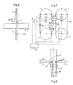
- Figure 1 illustrates schematically an installation which includes two mutually cooperating bandsaws provided with means for controlling blading-tension in accordance with the invention.
- Figure 2 is a schematic, horizontal view of the installation illustrated in Figure 1.
- Figure 3 is a schematic side view of one bandsaw illustrated in Figure 1.
- the reference numerals 1, 2 and 3, 4 in Figure 1 identify respectively the upper and the lower saw pulleys or wheels of two bandsaws.
- a respective sawblading 5 and 6 runs over each pair of pulleys and is stretched until the desired tension is achieved in the sawblading. Stretching of the sawblading is effected by subjecting the upper saw pulleys 1, 2 to a force F with the aid of a hydraulic piston-cylinder device or like device mounted on the saw frame.
- the tensioned sawblading will preferably be slightly resilient or springy, so as to reduce loading shocks.
- bandsaws and the manner of their construction may have any prior known form which will enable the blading-tention to be adjusted, the bandsaws and their construction will not be described in detail here. Examples of bandsaws of this kind are found described and illustrated in the aforesaid specifications, namely the Swedish Patent Specification 7312757-3 and WO 88/03850.
- the reference numeral 7 identifies a log being sawn
- the reference numeral 8 identifies a device for sensing and adjusting the tensioning force F, this device being connected to a microprocessor 9.
- the microprocessor also receives signals from a sensing device 10 operative to sense the sawblading area and a device 11 which is operative to detect any disturbance in or deviation from the ideal movement path of the sawblading, for instance disturbances in the form of vibrations, twists and the like.
- the devices 11 may consist of two inductive sensors each located on a respective edge of the sawblading but out of mechanical contact therewith.
- the pressure exerted by a tensioned sawblading against blading guides 12 can also be detected or sensed, inter alia, for the purpose of indicating fluctuations in said pressure.
- the reference 13 identifies a sensing arrangement of the video-camera type which is used to determine the linearity of the saw cut 14 and deviations of the saw cuts from ideal saw cuts.
- the microprocessor 9 receives data relating to, inter alia, possible fluctuations in the abutment pressure of the blading against the blading guides and possible twisting of or vibrations in the blading, and also data relating to the accuracy of the saw cut, or calculates such data on the basis of sensed measuring values, inter alia on the values of specific blading-tension.
- the microprocessor compares these parameters with limit values stored in the microprocessor, and when necessary sends a signal to the blading-tension adjusting device 8, indicating that the tension in the sawblading should be increased, in order to eliminate a particular disturbance or to improve sawing accuracy.
- the tension in the sawblading is adjusted, inter alia, in accordance with the logs concerned and the prevailing sharpness of the sawteeth.
- the tension in the sawblading is returned towards a preset starting value.
- the tension in the sawblading is again adjusted by application of the tensioning force F in dependence on the conditions which prevail in respect of this particular log.
- the tension in the sawblading is adjusted individually with each log and within limits which considerably optimize the accuracy of the saw cut and the useful length of life of the sawblading.
- the microprocessor 9 is preferably programmed to vary the basic level to which the sawblading is tensioned, so that the degree of tensioning is increased slightly with time during the use of the sawblading.
- This increase in blading-tension shall be based on the knowledge, gained by experience, of the extent to which blading-tension must be increased in order to maintain the desired sawing accuracy as the sawteeth lose their sharpness.
- the base value or starting value can also be preset with respect, e.g., to the dimensions of the logs or wood being sawn.
- the microprocessor can also be used to store data relating to the loading and operating time of the sawblading, the total load to which the sawblading is subjected being compared with an experience-value stored in the microprocessor and the microprocessor being programmed to indicate when sawblading should be replaced even when the sharpness of the sawteeth is satisfactory.
Landscapes
- Engineering & Computer Science (AREA)
- Mechanical Engineering (AREA)
- Sawing (AREA)
- Finish Polishing, Edge Sharpening, And Grinding By Specific Grinding Devices (AREA)
- Processing Of Stones Or Stones Resemblance Materials (AREA)
Abstract
Claims (5)
- Procédé de commande de la tension exercée sur la lame d'une scie à ruban à l'aide d'un dispositif de tension de lame pouvant être réglé électriquement, au moyen duquel la lame peut être tendue afin de régler la tension de la lame, caractérisé par les étapes de :- détermination au cours d'une opération de sciage, à l'aide de moyens d'actionnement automatiques, si la tension de lame est optimale ou non ;- détermination de ladite tension en détectant et déterminant au moins deux paramètres différents l'un de l'autre, déduits de la contrainte par unité de surface de la lame, des perturbations se produisant dans la trajectoire de déplacement de la lame, de la linéarité du trait de scie ;- traitement de signaux électriques qui correspondent auxdits paramètres dans un microprocesseur lorsque des écarts par rapport aux valeurs limites de paramètres programmées dans le microprocesseur ou des variations de paramètres sont déterminés, par transmission de signaux de commande depuis ledit microprocesseur vers le dispositif de tension de lame afin de régler la tension de lame ;- détermination au moyen desdits moyens d'actionnement automatiques du moment où la tension de lame est optimale ; et- cessation des signaux de commande transmis au dispositif de tension de lame lorsqu'une tension de lame optimale est établie.
- Procédé selon la revendication 1, caractérisé par le réglage automatique de la tension de la lame de scie par rapport à la superficie en coupe de la lame en service à ce moment-là.
- Procédé selon les revendications 1 ou 2, caractérisé par le fait que la tension de lame est ramenée à une valeur initiale de base avant d'entreprendre chaque nouvelle opération de sciage, à l'aide dudit microprocesseur.
- Procédé selon la revendication 3, caractérisé par l'accroissement de la valeur de base de ladite tension de lame en fonction du temps pendant lequel ladite lame de scie est utilisée.
- Dispositif destiné à commander la tension exercée sur les lames (5, 6) d'une scie à ruban à l'aide d'un dispositif de tension de lames à commande électrique au moyen duquel les lames peuvent être tendues pour régler la tension des lames à un niveau souhaité, caractérisé en ce que :- le dispositif comprend des moyens capteurs (10 à 13) dont la fonction est de détecter et déterminer au moins deux paramètres différents au cours d'une opération de sciage, et déduits de la contrainte par unité de surface des lames, des perturbations se produisant dans la trajectoire idéale de déplacement des lames, de la linéarité du trait de scie ;- le dispositif comprend également un microprocesseur (9) qui est alimenté en signaux électriques correspondant auxdits paramètres et qui, lors de la détermination d'écarts par rapport à des valeurs limites relatives auxdits paramètres programmés dans le microprocesseur ou à des variations des paramètres, agit pour émettre des signaux de commande vers le dispositif de tension des lames afin de produire un changement doux ou continu de ladite tension de lames jusqu'à ce que lesdits paramètres soient ramenées au dessous des valeurs limites.
Applications Claiming Priority (3)
| Application Number | Priority Date | Filing Date | Title |
|---|---|---|---|
| SE8901381A SE463856B (sv) | 1989-04-17 | 1989-04-17 | Saett och anordning foer styrning av saagbandspaenning |
| SE8901381 | 1989-04-17 | ||
| PCT/SE1990/000240 WO1990012669A1 (fr) | 1989-04-17 | 1990-04-06 | Procede et arrangement pour controler la tension d'une lame de scie a ruban |
Publications (2)
| Publication Number | Publication Date |
|---|---|
| EP0470195A1 EP0470195A1 (fr) | 1992-02-12 |
| EP0470195B1 true EP0470195B1 (fr) | 1995-07-19 |
Family
ID=20375697
Family Applications (1)
| Application Number | Title | Priority Date | Filing Date |
|---|---|---|---|
| EP90908098A Expired - Lifetime EP0470195B1 (fr) | 1989-04-17 | 1990-04-06 | Procede et arrangement pour controler la tension d'une lame de scie a ruban |
Country Status (7)
| Country | Link |
|---|---|
| EP (1) | EP0470195B1 (fr) |
| CA (1) | CA2050598C (fr) |
| DE (1) | DE69021055T2 (fr) |
| FI (1) | FI97608C (fr) |
| NO (1) | NO179482C (fr) |
| SE (1) | SE463856B (fr) |
| WO (1) | WO1990012669A1 (fr) |
Families Citing this family (4)
| Publication number | Priority date | Publication date | Assignee | Title |
|---|---|---|---|---|
| US7594462B2 (en) | 2004-08-23 | 2009-09-29 | Snodgrass Jr Howard L | Blade tension gauge |
| CN104520040B (zh) | 2012-08-17 | 2016-11-02 | 伊利诺斯工具制品有限公司 | 样品制备锯 |
| US10150172B2 (en) * | 2015-04-20 | 2018-12-11 | HE&M Inc. | Band saw blade sensor and control system |
| DE102019124750A1 (de) * | 2019-09-13 | 2021-03-18 | Robert Röntgen GmbH & Co. KG | Bandsägemaschine und Verfahren zum Betrieb einer Bandsägemaschine |
Family Cites Families (2)
| Publication number | Priority date | Publication date | Assignee | Title |
|---|---|---|---|---|
| US3680421A (en) * | 1970-07-10 | 1972-08-01 | Bemis Co Inc | Band saw apparatus |
| NL192433C (nl) * | 1985-09-17 | 1997-08-04 | Jongerius Bv | Snij-inrichting voor broden of dergelijke. |
-
1989
- 1989-04-17 SE SE8901381A patent/SE463856B/sv not_active IP Right Cessation
-
1990
- 1990-04-06 CA CA002050598A patent/CA2050598C/fr not_active Expired - Fee Related
- 1990-04-06 EP EP90908098A patent/EP0470195B1/fr not_active Expired - Lifetime
- 1990-04-06 WO PCT/SE1990/000240 patent/WO1990012669A1/fr not_active Ceased
- 1990-04-06 DE DE69021055T patent/DE69021055T2/de not_active Expired - Fee Related
-
1991
- 1991-10-14 FI FI914846A patent/FI97608C/fi not_active IP Right Cessation
- 1991-10-17 NO NO914086A patent/NO179482C/no not_active IP Right Cessation
Also Published As
| Publication number | Publication date |
|---|---|
| CA2050598A1 (fr) | 1990-10-18 |
| EP0470195A1 (fr) | 1992-02-12 |
| FI914846A0 (fi) | 1991-10-14 |
| FI97608C (fi) | 1997-01-27 |
| NO914086L (no) | 1991-10-17 |
| WO1990012669A1 (fr) | 1990-11-01 |
| SE8901381L (sv) | 1990-10-18 |
| DE69021055D1 (de) | 1995-08-24 |
| NO179482B (no) | 1996-07-08 |
| SE8901381D0 (sv) | 1989-04-17 |
| DE69021055T2 (de) | 1995-11-23 |
| NO179482C (no) | 1996-10-16 |
| FI97608B (fi) | 1996-10-15 |
| CA2050598C (fr) | 2001-04-03 |
| SE463856B (sv) | 1991-02-04 |
| NO914086D0 (no) | 1991-10-17 |
Similar Documents
| Publication | Publication Date | Title |
|---|---|---|
| US5694821A (en) | Method for controlling work feed rate for cutting wood, metal and other materials | |
| US6378408B2 (en) | Apparatus for variably controlling work feed rate for cutting wood, metal and other materials | |
| US10245660B2 (en) | Saw guide pressure feed speed control systems and methods | |
| US4644832A (en) | Method for monitoring saw blade stability and controlling work feed rate on circular saw and bandsaw machines | |
| US4416312A (en) | Guiding mechanism for timber cutting machines | |
| CA1056274A (fr) | Utilisation et outillage de scierie a ruban | |
| JP6555924B2 (ja) | 鋸盤および鋸盤を制御する方法 | |
| EP0470195B1 (fr) | Procede et arrangement pour controler la tension d'une lame de scie a ruban | |
| US10226828B2 (en) | System and method for controlling a feed-speed to a bandmill | |
| US4016787A (en) | Method for controlling the cutting feed speed of a saw frame of band-sawing machine or similar machine | |
| US3991644A (en) | Method for controlling the cutting feed speed of a saw frame of band-sawing machine or similar machine | |
| EP3500400B1 (fr) | Procédé et appareil de coupe précise à l'aide d'une scie circulaire | |
| AU2021253877B2 (en) | Method of cutting with a band saw | |
| CA2287217A1 (fr) | Technique de commande variable de la vitesse d'alimentation pendant la coupe de bois, de metal et d'autres materiaux | |
| US11396054B2 (en) | Method of cutting with a band saw | |
| EP4472814B1 (fr) | Machine pour diviser un corps en bois et procédé de commande d'une telle machine |
Legal Events
| Date | Code | Title | Description |
|---|---|---|---|
| PUAI | Public reference made under article 153(3) epc to a published international application that has entered the european phase |
Free format text: ORIGINAL CODE: 0009012 |
|
| 17P | Request for examination filed |
Effective date: 19910928 |
|
| AK | Designated contracting states |
Kind code of ref document: A1 Designated state(s): BE DE FR GB IT |
|
| 17Q | First examination report despatched |
Effective date: 19940620 |
|
| GRAA | (expected) grant |
Free format text: ORIGINAL CODE: 0009210 |
|
| AK | Designated contracting states |
Kind code of ref document: B1 Designated state(s): BE DE FR GB IT |
|
| ITF | It: translation for a ep patent filed | ||
| REF | Corresponds to: |
Ref document number: 69021055 Country of ref document: DE Date of ref document: 19950824 |
|
| ET | Fr: translation filed | ||
| PG25 | Lapsed in a contracting state [announced via postgrant information from national office to epo] |
Ref country code: GB Effective date: 19960406 |
|
| PG25 | Lapsed in a contracting state [announced via postgrant information from national office to epo] |
Ref country code: BE Effective date: 19960430 |
|
| PLBE | No opposition filed within time limit |
Free format text: ORIGINAL CODE: 0009261 |
|
| STAA | Information on the status of an ep patent application or granted ep patent |
Free format text: STATUS: NO OPPOSITION FILED WITHIN TIME LIMIT |
|
| 26N | No opposition filed | ||
| BERE | Be: lapsed |
Owner name: A K ERIKSSON A.B. Effective date: 19960430 |
|
| GBPC | Gb: european patent ceased through non-payment of renewal fee |
Effective date: 19960406 |
|
| PGFP | Annual fee paid to national office [announced via postgrant information from national office to epo] |
Ref country code: FR Payment date: 20030328 Year of fee payment: 14 |
|
| PG25 | Lapsed in a contracting state [announced via postgrant information from national office to epo] |
Ref country code: FR Free format text: LAPSE BECAUSE OF NON-PAYMENT OF DUE FEES Effective date: 20041231 |
|
| REG | Reference to a national code |
Ref country code: FR Ref legal event code: ST |
|
| PG25 | Lapsed in a contracting state [announced via postgrant information from national office to epo] |
Ref country code: IT Free format text: LAPSE BECAUSE OF NON-PAYMENT OF DUE FEES;WARNING: LAPSES OF ITALIAN PATENTS WITH EFFECTIVE DATE BEFORE 2007 MAY HAVE OCCURRED AT ANY TIME BEFORE 2007. THE CORRECT EFFECTIVE DATE MAY BE DIFFERENT FROM THE ONE RECORDED. Effective date: 20050406 |
|
| PGFP | Annual fee paid to national office [announced via postgrant information from national office to epo] |
Ref country code: DE Payment date: 20050427 Year of fee payment: 16 |
|
| PG25 | Lapsed in a contracting state [announced via postgrant information from national office to epo] |
Ref country code: DE Free format text: LAPSE BECAUSE OF NON-PAYMENT OF DUE FEES Effective date: 20061101 |