EP0470152B1 - Machine pour fabrication d'un paquet a partir d'un flan - Google Patents
Machine pour fabrication d'un paquet a partir d'un flan Download PDFInfo
- Publication number
- EP0470152B1 EP0470152B1 EP19900907211 EP90907211A EP0470152B1 EP 0470152 B1 EP0470152 B1 EP 0470152B1 EP 19900907211 EP19900907211 EP 19900907211 EP 90907211 A EP90907211 A EP 90907211A EP 0470152 B1 EP0470152 B1 EP 0470152B1
- Authority
- EP
- European Patent Office
- Prior art keywords
- carton
- blank
- product
- conveyor
- guide
- Prior art date
- Legal status (The legal status is an assumption and is not a legal conclusion. Google has not performed a legal analysis and makes no representation as to the accuracy of the status listed.)
- Expired - Lifetime
Links
- 238000004806 packaging method and process Methods 0.000 claims abstract description 37
- 230000033001 locomotion Effects 0.000 claims description 10
- 230000015572 biosynthetic process Effects 0.000 claims description 8
- 230000005484 gravity Effects 0.000 claims description 7
- 230000000750 progressive effect Effects 0.000 claims description 6
- 238000011144 upstream manufacturing Methods 0.000 claims description 2
- 235000013305 food Nutrition 0.000 description 12
- 239000000796 flavoring agent Substances 0.000 description 6
- 235000019634 flavors Nutrition 0.000 description 6
- 235000013618 yogurt Nutrition 0.000 description 6
- 239000000853 adhesive Substances 0.000 description 5
- 230000001070 adhesive effect Effects 0.000 description 5
- 230000007246 mechanism Effects 0.000 description 3
- 238000000034 method Methods 0.000 description 3
- 230000010006 flight Effects 0.000 description 2
- 238000004080 punching Methods 0.000 description 2
- 239000007787 solid Substances 0.000 description 2
- 239000004831 Hot glue Substances 0.000 description 1
- 238000010276 construction Methods 0.000 description 1
- 230000014759 maintenance of location Effects 0.000 description 1
- 239000000463 material Substances 0.000 description 1
- 239000002184 metal Substances 0.000 description 1
- 238000007493 shaping process Methods 0.000 description 1
Images
Classifications
-
- B—PERFORMING OPERATIONS; TRANSPORTING
- B65—CONVEYING; PACKING; STORING; HANDLING THIN OR FILAMENTARY MATERIAL
- B65B—MACHINES, APPARATUS OR DEVICES FOR, OR METHODS OF, PACKAGING ARTICLES OR MATERIALS; UNPACKING
- B65B11/00—Wrapping, e.g. partially or wholly enclosing, articles or quantities of material, in strips, sheets or blanks, of flexible material
- B65B11/06—Wrapping articles, or quantities of material, by conveying wrapper and contents in common defined paths
- B65B11/08—Wrapping articles, or quantities of material, by conveying wrapper and contents in common defined paths in a single straight path
- B65B11/10—Wrapping articles, or quantities of material, by conveying wrapper and contents in common defined paths in a single straight path to fold the wrappers in tubular form about contents
- B65B11/105—Wrapping articles, or quantities of material, by conveying wrapper and contents in common defined paths in a single straight path to fold the wrappers in tubular form about contents the axis of the tube being parallel to the conveying direction
Definitions
- This invention relates to a carton packaging machine which is operable to cause progressive erection of carton forming blanks, to permit loading of the partly erected blanks with products. to complete the formation of each carton and to close the latter with the product located therein and to discharge each closed carton from the machine.
- the invention is particularly concerned with a machine for use in forming carton sleeves, such machines being known as "sleeving machines".
- a stack of blanks is supplied to the machine, and the blanks are fed singularly to the machine and then undergo progressive erection, loading with product, final formation into sleeve form, and then discharge of the sleeve product.
- the present invention is concerned with a carton packaging machine of a general type which is disclosed in more detail in WO-A-88/04259 and to which reference is directed.
- the carton packaging machine disclosed therein is operable to cause progressive erection of carton sleeves from a supply of blanks, to permit loading of partly erected blanks with product, to complete the formation of a sleeve around each product and to close the latter with the product located therein and to discharge the loaded sleeve from the machine, in which the machine comprises: an endless conveyor moveable progressively through a blank-supply station, an erection station, a product loading station, a folding station and a discharge station; a magazine arranged at the blank-supply station for holding a stack of blanks; a suction device arranged to cooperate with the magazine and to operate in timed sequence with the operation of the conveyor in order to engage and to draw blanks individually in turn, in flat form, into the path of travel of the conveyor for engagement thereby; a shaping device arranged at the ere
- This carton packaging machine therefore enables the product to be loaded downwardly. This permits the product to be located in desired positions readily especially when loading takes place by hand.
- the present invention is concerned with the carton packaging machine of the general type referred to above, and which forms the subject of WO-A-88/04259, but seeks to improve this carton packaging machine in a number of respects, as will become apparent from the subsequent detailed description of the preferred embodimentof the invention herein.
- the carton packaging machine of the invention has been developed primarily though not exclusively, with a view to providing improved loading of cartons derived from blanks which are provided with circular apertures into which plastic pots, such as yoghurt pots can be suspended, and in which the blank is erected into a U-shape and then the side flaps are folded inwardly consecutively so as to overlie the tops of the product containers.
- the carton packaging machine of the invention may also provide improved loading of cartons formed from blanks which form a solid base to the cartons.
- Containers of any shape may be loaded onto the base of the container before the blank is folded to form a complete carton.
- the first aspect of the invention seeks to provide an improved carton packaging machine which is able to handle in an automatic manner blanks which can be readily folded into the required shape, and which provides a secure containment of the products in the packaging.
- a carton packaging machine which is operable to cause progressive erection of carton sleeves from a supply of blanks, each blank comprising a base and a pair of side flaps which can be folded inwardly so as to overlie the base when loaded with product
- the machine comprises: an endless conveyor moveable progressively through a blank-supply station; a product-loading station, at which products can be loaded onto respective bases; an erection and folding station; and a discharge station; a magazine arranged at the blank-supply station for holding a stack of blanks, and for delivering the blanks individually in turn, in flat form into the path of travel of the conveyor; a folding device arranged at the folding station and engageable by each blank in order to form the blank into a U-shape with the base thereof extending substantially horizontally and the pair of side flaps extending upwardly therefrom and to fold the side flaps inwardly into overlapping relation in order to complete the formation of the carton sleeve;
- the blanks can be supported reliably throughout the process at the various stations of the machine and particularly when the product is loaded into the base when the entire weight of the product is borne by the base of the blank.
- the machine is a "two-lane" machine, in which each lane of product can be arranged on a respective side of the elongate support. Further support for the blank during its travel through the various stations of the machine may be provided by means of generally horizontal rails extending alongside and above the upper run of the endless conveyor.
- the invention may be used in a machine having an automatic loading device, or with other types of loading devices, or with machines in which the loading is carried out by hand.
- a machine according to the second aspect of the invention may be used with blanks which are provided with circular apertures into which pots can be suspended or with blanks used to form cartons having a solid base.
- An automatic loading device is able to load each blank with the product automatically, and with the loading station being arranged at any convenient position along the length of the conveyor.
- the loading device has a first guide which extends transversely towards the conveyor, and preferably perpendicularly thereof, and which runs into a second guide which guides the product into movement in a direction generally parallel to the conveyor, whereby the product can then fall under gravity off the end of the second guide and onto the base of each underlying blank as it is conveyed through the loading station.
- the loading device has a first guide which extends transversely toward the conveyor, and which runs into a second guide which guides the product into movement in a direction generally parallel to the conveyor and further comprising ramp means located on the conveyor and positioned substantially below the second guide. The blank thus engages with the product before the product has fallen off the end of the second guide.
- each blank comprises a base having at least a pair of circular apertures to receive product to be suspended therein, and the automatic loading is arranged to guide two separate lanes of product towards respective products.
- carton blanks are supplied with at least two pairs of apertures, in which case the machine is provided with a further loading station arranged downstream of the first mentioned loading station, and having its own loading device.
- the first loading station can therefore fill the first pair of blank apertures with product (which may be the same product eg. the same flavour yoghurt, or two different flavours) and then the second loading station can fill the second pair of blank apertures with further products, which can be different from each other and/or different from the product(s) loaded at the first station if desired.
- This provides a flexible arrangement which will be of advantage to food manufacturers, as there will be four supply lanes which can be loaded with any required products eg to provide four yoghurt pots of the same flavour in each carton sleeve, or any desired combinations of flavour in a single carton sleeve.
- each loading device includes a pair of rotary indexing devices which are capable of advancing the products individually from each of the lanes from the first guide to the second guide, and conveniently each indexing device takes the form of a so called "star wheel” which is a rotary device having a plurality of circumferentially spaced sockets or pockets each shaped to be able to receive and to advance the product.
- the shape of the pockets will of course be determined by the shape of the product which is supplied.
- Very generally the product will be circular in cross sections, being of cylindrical or frusto-conical form.
- a carton-packaging machine which is operable to cause progressive erection of carton sleeves from a supply of blanks, each blank comprising a base and a pair of side flaps which can be folded inwardly so as to overlie the base when loaded with product
- the machine comprises: an endless conveyor moveable progressively through: a blank-supply station; a product loading station at which products can be loaded onto respective bases and an erection; and folding station; and a discharge station; a magazine arranged at the blank-supply station for holding a stack of blanks, and for delivering the blanks indivdually in turn in flat form, into the path of travel of the conveyor for engagement by flights carried by the conveyor; a folding device arranged at the folding station and engageable by each blank in order to form the blank into a U-shape with the base thereof extending substantially horizontally and a pair of side flaps extending upwardly therefrom and to fold the side flaps inwardly into overlapping relation in order to
- one of the side flaps is a short side flap and the other is a longer side flap which is capable of overlying the short side flap and also the entire base.
- a jet of hot melt adhesive may be applied to the upper side of the inwardly folded first flap and the subsequently folded longer flap is then pressed downwardly into adhesive engagement with the first folded short flap.
- additional means may be provided for securing the longer flap downwardly onto the base. This may involve the use of additional adhesive applied to the upper surface of the base, or alternatively a mechanical interlock may be provided.
- the mechanical interlock may be provided by punching a locking flap downwardly from the long overlapping sideflap and through a preformed locking recessing base.
- the conveyance of the loaded and folded cartons may be caused by means of variable speed endless driving belts which are pressed downwardly into engagement with the upper surfaces of the cartons.
- This arrangement may operate at a greater speed than that of the conveyor, so that loaded product can be rapidly discharged from the machine, thereby avoiding any risk of "bunching" of cartons taking place at entry to and during transit through, the folding station.
- the endless belts may be pressed downwardly by elongate rods, and the speed of the belts may be varied to suit requirements, by providing a V-belt and a variable pulley engagement therewith.
- the erection station may be operable to partially erect the cartons before the product is loaded into them.
- the erection station may be operable to erect the cartons after the product is loaded onto them.
- the machine further comprises sensing means positioned down stream of the loading station.
- the sensing means are positioned such that the absence of one or more products may be detected, as well as the absence of the blank. If the sensing means detect such the absence, of a product they will cause the endless conveyor to stop in order that the missing product may be replaced.
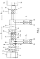
- a blank-supply station 11 is arranged at the upstream end of the machine, and includes the magazine 12 (not show in detail) which can hold a stack of blanks and permit supply of blanks individually in turn in flat form into the path of travel from the blank supply station 11 and through a product loading station 15, an erection station, a folding station and a discharge station, all of which can be of conventional form, and which are shown schematically by reference 16.
- the erection and folding mechanism may be as disclosed in more detail in UK Patent application number 8909783.6 filed on 28 April 1989 in the name of Bonar Cooke Carton Limited.
- each blank 17 has first and second pairs of apertures 18 and 19 into which food product, such as yoghurt containers can be loaded so as to be suspended therefrom.
- the apertures are arranged in the base 20 of the blank 17, and short side flap 21 and longer side flap 22 extend away from the base 20.
- blank 17 is discharged in flat form onto the conveyer 14 by the magazine 12, and in this form it is advanced through loading station 15 so as to receive in its apertures product from a two lane automatic loading device provided at the loading station 15.
- the automatic loading device is able to load the first pair of apertures 18 with product, and downstream of this first loading station 15, there is a further loading station 23 which is able to supply automatically two further lanes of product which are fed towards the conveyor perpendicularly thereof, and then guided along the length of the conveyor, finally to fall under gravity into the second pair of apertures 19.
- each loading station comprises an automatic loading device having a first guide 24 which guides product 25 along two lanes 26 which are side by side in a direction perpendicular to the general direction of the conveyor 14 and then the first guide 24 merges or runs into a second guide 27 which guides the product 25 via a curved portion 28 to move generally along the length of the conveyor, whereby the product can then fall under gravity off the free end 29 of a rectiliniar portion 27a of the second guide 27 and into the awaiting apertures of each blank.
- the products 25 are received by the first pair of apertures 18, whereas the automatic loading device at the second loading station 23 is able to guide two lanes of product into the second pair of apertures 19.
- each blank 17 After issue from the second loading station 23, each blank 17 has four products 25 received in its base apertures, and the blank is still in flat form.
- the conveyor 14 then conveys the loaded blanks towards the station 16, at which the side flaps 21 and 22 of the blanks are erected into a substantially vertical position, and then the upper edges of the side flaps are engaged and guided inwardly into overlapping relation and sealed closed in any convenient manner.
- the two loading stations 15 and 23 can enable each blank to be loaded with any desired combinations of product, such as a single flavour of yoghurt or different flavours, to meet the requirements of the food manufacturer. Different product runs can therefore readily be accommodated merely by change of supply of the products to the four supply lanes of the two loading devices.
- the product will preferably move under gravity along the first guide 24, and the rectilinear portions 27a of the second guide 27.
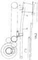
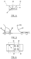
- power driven feeding devices are provided, as will now be described with reference to figure 2.
- Each lane 26 has associated therewith a rotary indexing device 31 which is able to engage and to advance the products 25 individually along the curve portion 28 and on to the rectilinear portion 27a of the second guide 27 and these products are advanced in timed sequence with the movement of the conveyor 14 so that the products fall under gravity off the end of the second guide 27 into the apertures 18 or 19 at the stations 15 and 23.
- Each indexing device 31 has a plurality of circumferentially spaced pockets 32 in which the products 25 are received, and effectively the devices 31 comprise so called "star wheels".
- Figure 3 shows in side view the portion 27a of the second guide 27, and suitable trip mechanisms will be arranged to ensure that product 25 can fall off the end and into the awaiting apertures at the correct time. Also, though not shown trip mechanisms may be arranged at or near the exit ends of the lanes 26, so that product can be advanced to the indexing devices 31 each time a fresh blank is advanced through the loading stations.
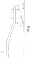
- FIG 3a an alternative arrangement of the second guide and the conveyor 14, is shown wherein the product 25 does not fall off the second guide until it has engaged in the blank 7.
- the end portion 29 of the second guide 27 holds the product in a position such that it is generally perpendicular to the conveyor 14.
- On the conveyor are positioned three ramps (only one of which is shown). As the blank 17 moves along the conveyor 14 it is raised up by the ramps 35. The product 25 is thus engaged in the blank 17 before it falls off the second guide 29.
- a mid-region 40 of the base 20 of each blank is supported by an elongate support 41 which extends longitudinally of the upper run of the conveyor and just out of engagement with the conveying surface of the conveyor.
- the flights 13 are shaped as shown in figure 4, so as not to engage the support 41 during movement of the conveyor.
- the support provided by the elongate support 41 provides rigidity to the base of each blank during transit through the various stations of the machine, and this is particularly useful during the loading of the base with food product which is suspended therefrom.
- Additional support for the base of each blank is provided by longitudinally extending side rails (not shown) arranged above the upper run of the conveyor 14, and this may be somewhat similar to the rail support provided in the carton packaging machine disclosed in international publication number WO88/04259.
- an overhead guide 50 is arranged downstream of the loading station as shown in figure 5, and applies gentle downward pressure onto the upper ends of the food containers.
- the guide may be hinged along its upper end 50a, and may thus may act as a safety device, causing the conveyor 14 to stop when the guide 50 is moved.
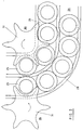
- the blanks Prior to the blanks arriving underneath the guide 50, the blanks pass beneath sensors 60. As shown in figure 6, there are 5 sensors 60. Four of the sensors 60 are each positioned so that they may sense the presence of a respective food product, and the fifth senser 60 is positioned so that it may sense the presence of the blank. In the event of one or more of the sensors 60 detecting the absence of a food product, the conveyor 14 will stop.
- each blank with product located is advanced to a folding device (not shown in detail), and which may take the form of conventional "ploughs", which apply consecutively inward folding of the short flap 21 and then the longer flap 22, but with the application of hot metal adhesive onto the upper side of short flap 21 immediately prior to application of longer flap 22 which is then adhesively pressed downwardly thereon.
- a folding device not shown in detail
- this will provide an acceptable form of packaging for this food product, although if additional rigidity is required for the assembled sleeve form of each blank (base plus overlapping side flap 21 and side flap 22), additional adhesive may be applied on the base 20.
- a mechanical interlock may be provided, by punching downwardly a locking tab out of the side flap and through a preformed locking recess in the base (20).
Landscapes
- Engineering & Computer Science (AREA)
- Mechanical Engineering (AREA)
- Supplying Of Containers To The Packaging Station (AREA)
Abstract
Claims (16)
- Machine (10) de conditionnement de cartons qui est destinée à provoquer une construction progressive de manchons de carton à partir d'une réserve de flans, chaque flan (17) ayant une base (20) et une paire de volets latéraux (21, 22) qui peuvent être pliés vers l'intérieur afin qu'ils recouvrent la base lorsqu'elle est chargée de produit, et qui comprend :
un transporteur sans fin (14) mobile progressivement à travers un poste (11) de distribution de flans, un poste (16) de chargement de produit auquel des produits peuvent être chargés dans des bases respectives, un poste (16) de construction et de pliage, et un poste d'évacuation,
un magasin (12) placé au poste de distribution de flans et destiné à maintenir une pile de flans et à distribuer les flans individuellement tour à tour sous forme plate sur le trajet de déplacement du transporteur, et
un appareil de pliage placé au poste de pliage et destiné à coopérer avec chaque flan afin qu'il mette celui-ci à une configuration en U dont la base est placée en direction sensiblement horizontale et la paire de volets latéraux dépasse vers le bas, et plie les volets latéraux vers l'intérieur afin qu'ils se recouvrent et que la formation du manchon de carton soit terminée, caractérisée en ce que la machine comporte en outre un support allongé (41) placé le long du transporteur et destiné à coopérer avec la face inférieure de la région médiane (40) de la base de chaque flan pendant le mouvement d'avance du flan du poste de distribution de flans au poste d'évacuation. - Machine de conditionnement de cartons selon la revendication 1, dans laquelle la machine est du type à "deux voies" dans laquelle chaque voie de produit peut être placée d'un côté respectif du support allongé.
- Machine de conditionnement de cartons selon la revendication 1 ou 2, comprenant des rails horizontaux de façon générale, disposés le long du brin supérieur du transporteur sans fin et au-dessus de ce brin.
- Machine de conditionnement de cartons selon l'une quelconque des revendications 1 à 3, dans laquelle chaque flan comporte une base (17) ayant au moins une paire d'ouvertures circulaires (18) pour le logement de produits suspendus dans les ouvertures.
- Machine de conditionnement de cartons selon l'une quelconque des revendications 1 à 4, dans laquelle le poste de chargement est un dispositif de chargement automatique (24, 27) destiné à guider au moins une voie du produit vers le transporteur et à charger chaque flan du produit respectif lorsque le flan avance sous l'action du transporteur au poste de chargement.
- Machine de conditionnement de cartons selon la revendication 5, dans laquelle l'appareil de chargement a un premier guide (24) placé transversalement vers le transporteur et qui débouche dans un second guide (27) qui guide le produit afin qu'il se déplace en direction parallèle de façon générale au transporteur, si bien que le produit peut tomber sous l'action de la pesanteur à l'extrémité du second guide et sur la base de chaque flan placé au-dessous lors de son transport au poste de chargement.
- Machine de conditionnement de cartons selon la revendication 5, dans laquelle l'appareil de chargement a un premier guide (24) placé transversalement vers le transporteur et qui débouche dans un second guide (27) qui guide le produit afin qu'il se déplace en direction parallèle de façon générale au transporteur, et comprenant en outre un dispositif à rampe (35) placé sur le transporteur (14) et pratiquement au-dessous du second guide.
- Machine de conditionnement de cartons selon la revendication 6, dans laquelle chaque flan comporte une base ayant au moins deux paires d'ouvertures circulaires (18, 19), la machine comportant en outre un second poste de chargement (23) placé en aval du premier poste de chargement et ayant son propre appareil de chargement.
- Machine de conditionnement de cartons selon l'une quelconque des revendications 6, 7 et 8, dans laquelle l'appareil ou chaque appareil de chargement comporte deux dispositifs rotatifs (31) de positionnement qui peuvent faire avancer les produits individuellement à partir de la voie ou de chaque voie, du premier guide au second.
- Machine de conditionnement de cartons selon la revendication 9, dans laquelle chaque appareil de positionnement est sous forme d'une "roue étoilée" qui est un dispositif rotatif ayant plusieurs poches ou logements espacés circonférentiellement (32) pouvant chacun recevoir le produit et le faire avancer.
- Machine selon l'une quelconque des revendications 1 à 10, comprenant en outre un guide suspendu (50) placé au poste de pliage en amont de l'appareil de pliage, le guide étant destiné à coopérer avec les parties supérieures des produits afin que ceux-ci soient positionnés fermement en place.
- Machine de conditionnement de cartons selon la revendication 11, dans laquelle le guide comprend une plaque de guidage (50) qui est disposée vers le bas et vers l'arrière par rapport à la direction de déplacement du transporteur, si bien qu'elle peut être fermement au contact des parties supérieures des récipients de produit.
- Machine de conditionnement de cartons selon la revendication 11 ou 12, comprenant en outre un dispositif de sécurité à action solidarisée.
- Machine de conditionnement de cartons selon l'une quelconque des revendications précédentes, dans laquelle l'un des volets latéraux (18) est un volet latéral court, et l'autre (19) est un volet latéral plus long qui peut recouvrir le volet latéral court ainsi que la totalité de la base.
- Machine de conditionnement de cartons selon l'une quelconque des revendications précédentes, comprenant en outre un dispositif supplémentaire de fixation du volet relativement long sur la base, vers le bas.
- Machine de conditionnement de cartons selon la revendication 15, dans laquelle le dispositif supplémentaire de fixation est un mécanisme à action solidarisée.
Applications Claiming Priority (4)
| Application Number | Priority Date | Filing Date | Title |
|---|---|---|---|
| GB898909783A GB8909783D0 (en) | 1989-04-28 | 1989-04-28 | Carton packaging machine |
| GB8909783 | 1989-04-28 | ||
| GB8923160 | 1989-10-13 | ||
| GB898923160A GB8923160D0 (en) | 1989-10-13 | 1989-10-13 | Carton packaging machine |
Publications (2)
| Publication Number | Publication Date |
|---|---|
| EP0470152A1 EP0470152A1 (fr) | 1992-02-12 |
| EP0470152B1 true EP0470152B1 (fr) | 1994-02-09 |
Family
ID=26295285
Family Applications (1)
| Application Number | Title | Priority Date | Filing Date |
|---|---|---|---|
| EP19900907211 Expired - Lifetime EP0470152B1 (fr) | 1989-04-28 | 1990-04-30 | Machine pour fabrication d'un paquet a partir d'un flan |
Country Status (3)
| Country | Link |
|---|---|
| EP (1) | EP0470152B1 (fr) |
| DE (1) | DE69006596D1 (fr) |
| WO (1) | WO1990013486A1 (fr) |
Cited By (1)
| Publication number | Priority date | Publication date | Assignee | Title |
|---|---|---|---|---|
| DE102023209591A1 (de) * | 2023-09-29 | 2025-04-03 | ZWi Technologies GmbH | Verpackungsmaschine |
Family Cites Families (3)
| Publication number | Priority date | Publication date | Assignee | Title |
|---|---|---|---|---|
| US2817197A (en) * | 1956-02-03 | 1957-12-24 | Gardner Board & Carton Co | Can packaging apparatus |
| FR1542725A (fr) * | 1967-09-06 | 1968-10-18 | Cartonnages Du Val De Seine | Emballage de groupement et machine pour sa réalisation automatique |
| GB8333706D0 (en) * | 1983-12-19 | 1984-01-25 | Mead Corp | Packaging machine method |
-
1990
- 1990-04-30 EP EP19900907211 patent/EP0470152B1/fr not_active Expired - Lifetime
- 1990-04-30 WO PCT/GB1990/000667 patent/WO1990013486A1/fr not_active Ceased
- 1990-04-30 DE DE90907211T patent/DE69006596D1/de not_active Expired - Lifetime
Cited By (2)
| Publication number | Priority date | Publication date | Assignee | Title |
|---|---|---|---|---|
| DE102023209591A1 (de) * | 2023-09-29 | 2025-04-03 | ZWi Technologies GmbH | Verpackungsmaschine |
| DE102023209591A8 (de) | 2023-09-29 | 2025-05-28 | ZWi Technologies GmbH | Verpackungsmaschine |
Also Published As
| Publication number | Publication date |
|---|---|
| WO1990013486A1 (fr) | 1990-11-15 |
| EP0470152A1 (fr) | 1992-02-12 |
| DE69006596D1 (de) | 1994-03-24 |
Similar Documents
| Publication | Publication Date | Title |
|---|---|---|
| CA2215965C (fr) | Machine de conditionnement pour emballages multiples | |
| EP0268611B1 (fr) | Procede et appareil d'introduction de recipients dans un emballage allonge | |
| KR930004547B1 (ko) | 물품분리 및 적하장치 | |
| EP0817748B1 (fr) | Mecanisme d'alimentation de structures porteuses et dispositif de chargement de recipients dans une structure porteuse ouverte sur le fond | |
| US5943847A (en) | Packaging machine for multi-packs | |
| US4443995A (en) | Metering device and method | |
| KR101501768B1 (ko) | 다수의 병 포장물을 일괄포장하는 랩 어라운드 포장기 | |
| US4571916A (en) | Secondary packaging machine | |
| US5481848A (en) | Method for feeding and preparing information leaflets on a product packaging line and a system for implementing this method | |
| US4709538A (en) | Apparatus for feeding and opening a beverage carrier | |
| GB2141093A (en) | Erecting trays about their contents | |
| CA1141646A (fr) | Emballeuse mecanique | |
| EP0470152B1 (fr) | Machine pour fabrication d'un paquet a partir d'un flan | |
| US10829250B2 (en) | Methods and machine for packaging primary containers in secondary containers and a shipping tray | |
| EP0092402A2 (fr) | Appareil pour l'emballage en carton | |
| KR20170014981A (ko) | 미닫이 상자 포장의 자동포장 시스템에 있어서 속상자 자동 폴딩 공급장치 | |
| EP0270528B1 (fr) | Procede et appareil de montage, de remplissage et de fermeture d'une ebauche d'emballage, et ebauche d'emballage | |
| EP0337997B1 (fr) | Machine d'emballage de produits dans des boites en carton | |
| CA1316446C (fr) | Machine a emballer sous carton | |
| CA2295360A1 (fr) | Machine pour le pliage vers le bas d'une section inferieure de boite d'emballage sous un produit en cours d'emballage |
Legal Events
| Date | Code | Title | Description |
|---|---|---|---|
| PUAI | Public reference made under article 153(3) epc to a published international application that has entered the european phase |
Free format text: ORIGINAL CODE: 0009012 |
|
| 17P | Request for examination filed |
Effective date: 19911127 |
|
| AK | Designated contracting states |
Kind code of ref document: A1 Designated state(s): DE ES FR GB IT NL |
|
| 17Q | First examination report despatched |
Effective date: 19921112 |
|
| GRAA | (expected) grant |
Free format text: ORIGINAL CODE: 0009210 |
|
| AK | Designated contracting states |
Kind code of ref document: B1 Designated state(s): DE ES FR GB IT NL |
|
| PG25 | Lapsed in a contracting state [announced via postgrant information from national office to epo] |
Ref country code: IT Free format text: LAPSE BECAUSE OF FAILURE TO SUBMIT A TRANSLATION OF THE DESCRIPTION OR TO PAY THE FEE WITHIN THE PRE;WARNING: LAPSES OF ITALIAN PATENTS WITH EFFECTIVE DATE BEFORE 2007 MAY HAVE OCCURRED AT ANY TIME BEFORE 2007. THE CORRECT EFFECTIVE DATE MAY BE DIFFERENT FROM THE ONE RECORDED.SCRIBED TIME-LIMIT Effective date: 19940209 Ref country code: NL Effective date: 19940209 Ref country code: DE Effective date: 19940209 Ref country code: FR Free format text: THE PATENT HAS BEEN ANNULLED BY A DECISION OF A NATIONAL AUTHORITY Effective date: 19940209 Ref country code: ES Free format text: THE PATENT HAS BEEN ANNULLED BY A DECISION OF A NATIONAL AUTHORITY Effective date: 19940209 |
|
| REF | Corresponds to: |
Ref document number: 69006596 Country of ref document: DE Date of ref document: 19940324 |
|
| PG25 | Lapsed in a contracting state [announced via postgrant information from national office to epo] |
Ref country code: GB Effective date: 19940509 |
|
| EN | Fr: translation not filed | ||
| NLV1 | Nl: lapsed or annulled due to failure to fulfill the requirements of art. 29p and 29m of the patents act | ||
| PLBE | No opposition filed within time limit |
Free format text: ORIGINAL CODE: 0009261 |
|
| STAA | Information on the status of an ep patent application or granted ep patent |
Free format text: STATUS: NO OPPOSITION FILED WITHIN TIME LIMIT |
|
| GBPC | Gb: european patent ceased through non-payment of renewal fee |
Effective date: 19940509 |
|
| 26N | No opposition filed |