EP0470142B1 - Vorrichtung zum auffüllen eines behälters mit schüttgut - Google Patents
Vorrichtung zum auffüllen eines behälters mit schüttgut Download PDFInfo
- Publication number
- EP0470142B1 EP0470142B1 EP90907099A EP90907099A EP0470142B1 EP 0470142 B1 EP0470142 B1 EP 0470142B1 EP 90907099 A EP90907099 A EP 90907099A EP 90907099 A EP90907099 A EP 90907099A EP 0470142 B1 EP0470142 B1 EP 0470142B1
- Authority
- EP
- European Patent Office
- Prior art keywords
- plate
- tube
- solids
- radius
- plates
- Prior art date
- Legal status (The legal status is an assumption and is not a legal conclusion. Google has not performed a legal analysis and makes no representation as to the accuracy of the status listed.)
- Expired - Lifetime
Links
- 239000012265 solid product Substances 0.000 title abstract description 3
- 239000007787 solid Substances 0.000 claims abstract description 42
- 239000006185 dispersion Substances 0.000 claims abstract description 15
- 230000007423 decrease Effects 0.000 claims description 7
- 230000005484 gravity Effects 0.000 claims description 4
- 230000006978 adaptation Effects 0.000 claims 1
- 239000002245 particle Substances 0.000 abstract description 6
- 239000003054 catalyst Substances 0.000 description 7
- 229920000297 Rayon Polymers 0.000 description 3
- 235000013339 cereals Nutrition 0.000 description 3
- 230000003247 decreasing effect Effects 0.000 description 3
- 239000000047 product Substances 0.000 description 3
- 239000002964 rayon Substances 0.000 description 3
- 230000000694 effects Effects 0.000 description 2
- 235000013305 food Nutrition 0.000 description 2
- 238000002407 reforming Methods 0.000 description 2
- 239000000126 substance Substances 0.000 description 2
- 238000009423 ventilation Methods 0.000 description 2
- GYHNNYVSQQEPJS-UHFFFAOYSA-N Gallium Chemical compound [Ga] GYHNNYVSQQEPJS-UHFFFAOYSA-N 0.000 description 1
- 229920000426 Microplastic Polymers 0.000 description 1
- 240000008042 Zea mays Species 0.000 description 1
- 239000003463 adsorbent Substances 0.000 description 1
- 150000004945 aromatic hydrocarbons Chemical class 0.000 description 1
- 239000004464 cereal grain Substances 0.000 description 1
- 239000003153 chemical reaction reagent Substances 0.000 description 1
- 239000002537 cosmetic Substances 0.000 description 1
- 238000013461 design Methods 0.000 description 1
- 239000008298 dragée Substances 0.000 description 1
- 239000003814 drug Substances 0.000 description 1
- 230000008030 elimination Effects 0.000 description 1
- 238000003379 elimination reaction Methods 0.000 description 1
- 239000003337 fertilizer Substances 0.000 description 1
- 239000012530 fluid Substances 0.000 description 1
- 229910052733 gallium Inorganic materials 0.000 description 1
- 239000008187 granular material Substances 0.000 description 1
- 244000144972 livestock Species 0.000 description 1
- 238000000034 method Methods 0.000 description 1
- 238000012856 packing Methods 0.000 description 1
- 239000000843 powder Substances 0.000 description 1
- 125000006850 spacer group Chemical group 0.000 description 1
- 238000012360 testing method Methods 0.000 description 1
- 238000012546 transfer Methods 0.000 description 1
- 239000010457 zeolite Substances 0.000 description 1
Images


Classifications
-
- B—PERFORMING OPERATIONS; TRANSPORTING
- B01—PHYSICAL OR CHEMICAL PROCESSES OR APPARATUS IN GENERAL
- B01J—CHEMICAL OR PHYSICAL PROCESSES, e.g. CATALYSIS OR COLLOID CHEMISTRY; THEIR RELEVANT APPARATUS
- B01J8/00—Chemical or physical processes in general, conducted in the presence of fluids and solid particles; Apparatus for such processes
- B01J8/0015—Feeding of the particles in the reactor; Evacuation of the particles out of the reactor
- B01J8/002—Feeding of the particles in the reactor; Evacuation of the particles out of the reactor with a moving instrument
-
- B—PERFORMING OPERATIONS; TRANSPORTING
- B65—CONVEYING; PACKING; STORING; HANDLING THIN OR FILAMENTARY MATERIAL
- B65G—TRANSPORT OR STORAGE DEVICES, e.g. CONVEYORS FOR LOADING OR TIPPING, SHOP CONVEYOR SYSTEMS OR PNEUMATIC TUBE CONVEYORS
- B65G69/00—Auxiliary measures taken, or devices used, in connection with loading or unloading
- B65G69/04—Spreading out the materials conveyed over the whole surface to be loaded; Trimming heaps of loose materials
- B65G69/0458—Spreading out the materials conveyed over the whole surface to be loaded; Trimming heaps of loose materials with rotating means, e.g. tables, arms
-
- B—PERFORMING OPERATIONS; TRANSPORTING
- B01—PHYSICAL OR CHEMICAL PROCESSES OR APPARATUS IN GENERAL
- B01J—CHEMICAL OR PHYSICAL PROCESSES, e.g. CATALYSIS OR COLLOID CHEMISTRY; THEIR RELEVANT APPARATUS
- B01J2208/00—Processes carried out in the presence of solid particles; Reactors therefor
- B01J2208/00743—Feeding or discharging of solids
- B01J2208/00752—Feeding
-
- B—PERFORMING OPERATIONS; TRANSPORTING
- B01—PHYSICAL OR CHEMICAL PROCESSES OR APPARATUS IN GENERAL
- B01J—CHEMICAL OR PHYSICAL PROCESSES, e.g. CATALYSIS OR COLLOID CHEMISTRY; THEIR RELEVANT APPARATUS
- B01J2208/00—Processes carried out in the presence of solid particles; Reactors therefor
- B01J2208/00743—Feeding or discharging of solids
- B01J2208/00769—Details of feeding or discharging
- B01J2208/00778—Kinetic energy reducing devices in the flow channel
Definitions
- the object of the present invention is to define an apparatus which makes it possible to achieve an increase in the quantity of solid introduced into a certain volume.
- Usual storage concerns cereal grains (silos), food products intended for consumption or livestock, food, fertilizers, chemicals, plastic pellets, pharmaceuticals and / or cosmetics, and all other divided solid (grains or dragees, or extruded granules, tablets, agglomerates, crushed, etc.).
- Their other field of application consists of containers or chemical reactors intended to be filled with solid particles: catalysts, adsorbents, reagents, packings, various fillings ...
- FIG 1 illustrates the invention.
- the device consists of a fixed feed hopper (1) preferably containing in its center a motor (2), for example pneumatic, possibly supplied by a gas (air for example).
- This engine is integral with the hopper.
- the motor (2) drives a shaft (3) which rotates a dispersion head to which this shaft is fixed.
- This dispersing head comprises at least two plates, preferably at least three or four plates.
- the plate (7) rotates around the tube (10) and it is supplied by the downpipe (9), preferably fixed and itself connected to the bearing (8).
- the other solid downpipes (10), (11) and (12) fixed or moved with preferably a small rotational movement, and of increasingly smaller diameter, create concentric annular spaces allowing the grains or granular solids to feed the plates (6), (5) and (4) respectively.
- the plates (6) and (5) rotate respectively around the tubes (10), (11) and (12).
- the plate (4) rotates around the shaft (3). Under the effect of centrifugal force, the solid particles are projected into the volume to be filled.
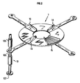
- the plates (7), (6), (5), (4) may be equipped (see FIG. 2) with at least one deflector.
- deflectors When several deflectors are used, these can be identical or different, flexible or hard (such as (14), (15), (16) in FIG. 2, the use of which is to promote dispersion and the projection of the grains).
- FIG. 2 represents a plate, here plate 7, in perspective.
- These deflectors will have varied shapes suitable for the shape of the powder particles.
- the radii of the trays can be adjustable, that is to say increased or decreased to create or to increase the width of the ring of solids projected at the bottom of the container (for example crowns E1, E2, E3 and E4 in FIG. 4 ). There are thus easily adaptable or modifiable trays for preliminary filling tests.
- FIG. 3 illustrates a tray in the following 4 cases: deflector (18) of Figure 2.
- deflector (16) of Figure 2 tray with straight or curved ridges, tray with corrugated surface (for better attachment of solids.
- the lower plate ((4) in Figures 1 and 4) can be fitted with a self-regulating flow system (with automatic opening) adapting to the rotation or filling speed (weights (13) in Figure 1 ).
- the same principle can equip the other platforms.
- the speed of rotation of a plate can vary between 15 and 780 revolutions per minute.
- FIG. 4 also illustrates the invention.
- a container (100) which is to be filled with pulverulent solids using the apparatus according to the invention.
- the pipe (101) allows granular solids to be introduced into the apparatus according to the invention.
- the neck (103) (or reactor flange) makes it possible to fix the apparatus according to the invention in the upper part of the enclosure (100).
- a grid (104) can facilitate the flow of solids towards the apparatus according to the invention.
- This figure 4 clearly shows that each tray (or stage) sprinkles its own crown at the bottom of the container, which gradually fills homogeneously.
- the invention is particularly suitable for supplying catalyst to reforming reactors, for producing aromatic hydrocarbons from various feeds, for example C2-C3, C2-C5, C2-C7, C5-C7, C2-C10 etc. with reforming type catalysts or with catalysts based on zeolites of MFI type containing or not various promoters, such as for example gallium.
- FIG. 5 illustrates the apparatus, when the embodiment of the apparatus corresponds to a spiral shape.
- Each plate 4, 5, 6, 7, (powered by a motor (2)) has a spiral shape.
- the spiral can be of continuous shape. Continuity will be from one plateau to another; as indicated above, for an intermediate plate, the shortest radius of the spiral may correspond to the longest radius of the spiral of the plate below. The longest radius corresponds to the shortest radius of the spiral of the top plate.
- the plates can be provided with strips (tubes or profiles in particular), for example flat radial strips or curved radial strips.
- FIG. 5 illustrates an exploded view of the trays.
- FIG. 6 illustrates the aerial view of the plates, thus showing the continuous appearance of a single spiral.
- the following table gives, for various pulverulent solids, on the one hand, the filling density obtained when the divided solids are poured in bulk into a container, and on the other hand when they are introduced into the container in accordance with the present invention.
Landscapes
- Chemical & Material Sciences (AREA)
- Organic Chemistry (AREA)
- Chemical Kinetics & Catalysis (AREA)
- Engineering & Computer Science (AREA)
- Mechanical Engineering (AREA)
- Devices And Processes Conducted In The Presence Of Fluids And Solid Particles (AREA)
- Basic Packing Technique (AREA)
- Filling Or Emptying Of Bunkers, Hoppers, And Tanks (AREA)
Claims (9)
- Vorrichtung zum Befüllen eines Behälters mit einem stückigen Produkt oder stückigen Feststoffen, die folgendes umfaßt:- einen Trichter (1), der mit einem Motor (2) versehen ist, der mit dem Trichter fest verbunden ist,- eine genau vertikale Welle (3), die durch den Motor (2) angetrieben wird,- einen Verteilerkopf, der durch den besagten Motor in Rotation versetzt wird, wobei der Verteilerkopf mindestens drei Platten umfaßt, (wie zum Beispiel (7), (6), (5) und (4)), die genau parallel und koaxial angeordnet sind und genau eine der folgenden Formen besitzen, nämlich: kreisförmig, elliptisch, spiralförmig, die Platten sind untereinander angeordnet, und ihr Radius verkleinert sich von der obersten Platte zur untersten Platte immer weiter,- eine Folge von mindestens drei Röhren (wie zum Beispiel (9), (10), (11) und (12)), die genau die Form von konzentrischen Zylindern besitzen, gestapelt und koaxial, verschiebbar, in denen die stückigen Feststoffe durch ihr Gewicht herunterfallen, wobei das untere Ende eines jeden Zylinders sich über einer Platte befindet und das obere Ende eines jeden Zylinders außer dem obersten sich genau auf Höhe des unteren Endes des darüberliegenden Zylinders befindet, und wobei der Durchmesser jeder Röhre mit Ausnahme der obersten Röhre kleiner ist als der Durchmesser der Röhre, die über ihr steht, mit Ausnahme der untersten Röhre, größer ist als der Durchmesser der Röhre, über der sie steht und so ist jede Platte, mit Ausnahme der untersten Platte, mit einer Röhre verbunden, um die sie sich dreht; wobei der Radius der Röhre kleiner ist als der kleinste Abstand zwischen dem äußeren Rand der Platte und der Achse, um die sich die besagte Platte dreht, die unterste Platte dreht sich um die Welle (3); ein Teil des stückigen Feststoffs fällt von jeder Röhre, mit Ausnahme der untersten Röhre, in die Röhre direkt darunter, ein anderer Teil des Feststoffes fällt von jeder Röhre auf die Platte, über der sie mündet, die stückigen Feststoffe, die auf diese Platte fallen, werden einer Rotationsbewegung aufgrund der Rotation der Platte, auf die sie gefallen sind, unterworfen; die Zentrifugalkraft, die durch die Rotation der Platten erzeugt wird, ermöglicht es, die Feststoffe in unterschiedlichen Abständen zur Achse der Welle auszuschleudern, die genau proportional zum Radius der Platte sind, von der aus die Feststoffe in den zu befüllenden Behälter ausgeworfen worden sind.
- Vorrichtung gemäß Anspruch 1), bei der die konzentrischen Röhren keine relative Rotationsbewegung um die vertikale Achse, bezogen auf den Verteilerkopf, ausführen können.
- Vorrichtung gemäß Anspruch 1), bei der die konzentrischen Röhren eine relative Rotationsbewegung um dieselbe vertikale Achse, bezogen auf den Verteilerkopf, ausführen können.
- Vorrichtung gemäß einem der Ansprüche 1 und 3, bei der mindestens eine Platte mit mindestens einer Ablenkvorrichtung versehen ist.
- Vorrichtung gemäß Anspruch 4, bei der die Größe des Radius von mindestens einer Platte variiert werden kann.
- Vorrichtung gemäß einem der Ansprüche 1 bis 5, bei der die unterste Platte mit einem den Durchsatz selbstregulierenden System ausgestattet ist, das sich an die Rotationsgeschwindigkeit oder an den Füllstand anpaßt.
- Vorrichtung gemäß einem der Ansprüche 1 bis 6, bei der jede der Platten mit dem gleichen selbstregulierenden System ausgerüstet ist.
- Vorrichtung gemäß Anspruch 7, bei dem das besagte selbstregulierende System aus Speisern besteht.
- Vorrichtung gemäß einem der Ansprüche 1 bis 8, die im besonderen mindestens drei Platten (wie zum Beispiel (7), (6), (5) und (4) (siehe Abbildung 5)) umfaßt, die genau parallel und koaxial und genau elliptisch sind und untereinander angeordnet sind und deren Radius sich von der obersten zur untersten Platte immer weiter verringert.
Priority Applications (1)
| Application Number | Priority Date | Filing Date | Title |
|---|---|---|---|
| AT90907099T ATE91269T1 (de) | 1989-04-27 | 1990-04-19 | Vorrichtung zum auffuellen eines behaelters mit schuettgut. |
Applications Claiming Priority (6)
| Application Number | Priority Date | Filing Date | Title |
|---|---|---|---|
| FR8905780A FR2646399B1 (fr) | 1989-04-27 | 1989-04-27 | Appareillage pour le remplissage d'un recipient par un produit solide divise |
| FR8905780 | 1989-04-27 | ||
| FR8910287A FR2650250B2 (fr) | 1989-04-27 | 1989-07-27 | Appareillage pour le remplissage d'un recipient |
| FR8910287 | 1989-07-27 | ||
| FR8913469A FR2653092B2 (fr) | 1989-04-27 | 1989-10-12 | Appareillage pour le remplissage d'un recipient avec des particules de solides divises. |
| FR8913469 | 1989-10-12 |
Publications (2)
| Publication Number | Publication Date |
|---|---|
| EP0470142A1 EP0470142A1 (de) | 1992-02-12 |
| EP0470142B1 true EP0470142B1 (de) | 1993-07-07 |
Family
ID=27251880
Family Applications (1)
| Application Number | Title | Priority Date | Filing Date |
|---|---|---|---|
| EP90907099A Expired - Lifetime EP0470142B1 (de) | 1989-04-27 | 1990-04-19 | Vorrichtung zum auffüllen eines behälters mit schüttgut |
Country Status (5)
| Country | Link |
|---|---|
| US (1) | US5238035A (de) |
| EP (1) | EP0470142B1 (de) |
| CA (1) | CA2051661C (de) |
| ES (1) | ES2044586T3 (de) |
| WO (1) | WO1990012746A1 (de) |
Families Citing this family (25)
| Publication number | Priority date | Publication date | Assignee | Title |
|---|---|---|---|---|
| US5348434A (en) * | 1992-10-21 | 1994-09-20 | East Coast Terminal Assoc., Ltd. | Cargo loading system |
| US5421379A (en) * | 1993-09-24 | 1995-06-06 | Ctb Inc. | Method and apparatus for distributing granular material within a container |
| US5906293A (en) * | 1993-09-24 | 1999-05-25 | Ctb, Inc. | Method and apparatus for maintaining uniform mass flow of granular material out of a container |
| FR2721900B1 (fr) * | 1994-06-30 | 1996-08-23 | Inst Francais Du Petrole | Appareillage pour le remplissage d'un recipient avec des particules spheriques |
| US5746258A (en) * | 1996-04-03 | 1998-05-05 | Waeschle Inc. | Apparatus for filling a container with free-flowing bulk material |
| US5836362A (en) * | 1997-07-15 | 1998-11-17 | Praxair Technology, Inc. | Multiple adsorbent loading method and apparatus for a radial flow vessel |
| IT1299513B1 (it) * | 1998-06-12 | 2000-03-16 | Autostrade Concess Const | Silo modulare di stoccaggio di cloruri solidi ed in soluzione, dotato di sistema a disco distributore a getto indirizzabile |
| FR2812824B1 (fr) * | 2000-08-10 | 2003-05-30 | Total Raffinage Distribution | Nouveau procede de chargement homogene de particules solides dans une enceinte |
| US6571990B2 (en) | 2001-03-30 | 2003-06-03 | Ctb Ip, Inc. | Method and apparatus for adjustably directing granular material out of a container and reducing outlet pressure in the container |
| NO317083B1 (no) * | 2002-09-27 | 2004-08-02 | Catalyst Services Inc | Fremgangsmate for fylling av partikulaert materiale i vertikale ror |
| US6729365B1 (en) | 2003-03-28 | 2004-05-04 | Laval Cote | Distribution device for use with a silo |
| FR2862625B1 (fr) * | 2003-11-25 | 2006-02-10 | Bernard Poussin | Appareil destine au remplissage d'un recipient, avec des particules solides |
| US7427182B2 (en) * | 2004-12-01 | 2008-09-23 | Intray Consolidated Pty Ltd | Agitator loading system |
| BRPI0608479A2 (pt) * | 2005-03-25 | 2010-01-05 | Catalyst Services Inc | tubos de enchimento com catalisador e/ou outros particulados |
| US20080086932A1 (en) * | 2006-10-13 | 2008-04-17 | Cook Peter J | Insect-attraction apparatus |
| US8123452B2 (en) * | 2006-10-31 | 2012-02-28 | Sukup Manufacturing Co. | Pre-spread device for grain spreader |
| US7987879B2 (en) * | 2007-03-07 | 2011-08-02 | Cat Tech, Inc. | Methods and apparatus for dense particle loading |
| US8025472B2 (en) * | 2007-06-01 | 2011-09-27 | Catalyst Services, Inc. | Catalyst loading system |
| FR2940641B1 (fr) * | 2008-12-31 | 2013-02-01 | Total Raffinage Marketing | Dispositif pour le chargement de particules solides dans une enceinte |
| FR2954302B1 (fr) | 2009-12-21 | 2012-05-25 | Total Raffinage Marketing | Dispositif pour le chargement de particules solides dans une enceinte |
| FR2969587B1 (fr) * | 2010-12-27 | 2013-01-04 | Total Raffinage Marketing | Dispositif allege de chargement de particules solides |
| DE102011054086B4 (de) * | 2011-09-30 | 2013-05-23 | Thyssenkrupp Polysius Ag | Walzenmühle und Verfahren zur Zerkleinerung von sprödem Mahlgut |
| AT511804B1 (de) * | 2011-11-17 | 2013-03-15 | Berndorf Band Gmbh | Vorrichtung zur herstellung einer platte aus kunststeinmaterial |
| MX392527B (es) | 2015-04-29 | 2025-03-24 | Clpros Llc | Carga de tubos verticales con material particulado. |
| MX2022008082A (es) * | 2020-05-15 | 2022-07-11 | Tetra Laval Holdings & Finance | Metodo y dispositivo para llenar material en polvo en una bolsa. |
Family Cites Families (26)
| Publication number | Priority date | Publication date | Assignee | Title |
|---|---|---|---|---|
| US1560800A (en) * | 1922-09-13 | 1925-11-10 | Edward Mckain | Feeding and distributing apparatus for roller mills |
| FR1438867A (fr) * | 1964-07-03 | 1966-05-13 | Alfa Laval Ab | Appareil pour répartir des matières dans des récipients de stockage, tels que silos |
| US3428156A (en) * | 1967-01-23 | 1969-02-18 | Kaiser Ind Corp | Expandable chute device |
| NL161033C (nl) * | 1967-12-27 | 1980-01-15 | Lely Nv C Van Der | Inrichting voor het verspreiden van materiaal. |
| US3469718A (en) * | 1968-02-01 | 1969-09-30 | Grove Mfg Co | Spreader for grain bins |
| US3599878A (en) * | 1969-06-10 | 1971-08-17 | Dale Corp Van | Distributor apparatus |
| US3626964A (en) * | 1970-09-03 | 1971-12-14 | Wheelabrator Corp | Regulating valve for magnetic materials |
| US3966124A (en) * | 1974-03-20 | 1976-06-29 | Sukup Eugene G | Spreader for grain and like material |
| US4135560A (en) * | 1976-12-20 | 1979-01-23 | Union Carbide Corporation | Apparatus for filling bulk material containers |
| DE2703329C3 (de) * | 1977-01-27 | 1981-04-16 | Gebrüder Weiss KG, 6340 Dillenburg | Anordnung zum niveaugleichen Auffüllen von senkrechtstehenden Behältern |
| GB2014189B (en) * | 1977-12-21 | 1982-06-09 | Bristol Aerojet Ltd | Processes for the electrodeposition of composite coatings |
| US4300725A (en) * | 1979-09-13 | 1981-11-17 | Moherek Edward F | Apparatus for uniformly dispensing and distributing material |
| SU1005696A1 (ru) * | 1981-04-02 | 1983-03-23 | Bersenev Aleksandr | Разбрасыватель минеральных удобрений |
| BE899420A (nl) * | 1984-04-13 | 1984-07-31 | Transtec Operating Ltd Company | Inrichting voor het aanvoeren, verdelen en kompakteren van los gestorte stoffen in een opslaghouder, voertuig of vaartuig. |
| US4972884A (en) * | 1984-12-07 | 1990-11-27 | Chevron Research & Technology Company | Method and apparatus for uniformly loading particulate material into cylindrical beds |
| IN166220B (de) * | 1984-12-07 | 1990-03-31 | Chevron Res | |
| US4727913A (en) * | 1986-03-03 | 1988-03-01 | Occidental Chemical Corporation | Dust control loading device |
| DE3855726D1 (de) * | 1987-03-06 | 1997-02-06 | Amazonen Werke Dreyer H | Schleuderdüngerstreuer |
| DE3708653C2 (de) * | 1987-03-17 | 1996-01-18 | Agrichema Materialflusstechnik | Verladevorrichtung für lose Verladung von staubigen Schüttgütern |
| SU1495206A1 (ru) * | 1987-06-26 | 1989-07-23 | Институт Горного Дела Со Ан Ссср | Устройство дл дозировани порошковых материалов |
| DK168185B1 (da) * | 1988-02-15 | 1994-02-28 | Laursen As A P | Maskine af centrifugalspredertypen til udstrøning af korn- og pulverformet materiale |
| US4857205A (en) * | 1988-02-22 | 1989-08-15 | Petrolite Corporation | Method for inhibition of scale formation |
| US4821861A (en) * | 1988-05-31 | 1989-04-18 | Robert Shanahan | Bulk material chute system |
| GB8814275D0 (en) * | 1988-06-16 | 1988-07-20 | Dow Chemical Gmbh | Process for preparing aminomethylphosphonic chelating agent |
| DK0427935T3 (da) * | 1989-11-03 | 1995-10-16 | Amazonen Werke Dreyer H | Fremgangsmåde til anvendelse af en centrifugalgødningsspreder |
| EP1472285A2 (de) * | 2001-01-16 | 2004-11-03 | Incyte Genomics, Inc. | Sekretorische moleküle |
-
1990
- 1990-04-19 EP EP90907099A patent/EP0470142B1/de not_active Expired - Lifetime
- 1990-04-19 CA CA002051661A patent/CA2051661C/fr not_active Expired - Lifetime
- 1990-04-19 WO PCT/FR1990/000284 patent/WO1990012746A1/fr not_active Ceased
- 1990-04-19 US US07/781,166 patent/US5238035A/en not_active Expired - Lifetime
- 1990-04-19 ES ES90907099T patent/ES2044586T3/es not_active Expired - Lifetime
Also Published As
| Publication number | Publication date |
|---|---|
| ES2044586T3 (es) | 1994-01-01 |
| CA2051661A1 (fr) | 1990-10-28 |
| CA2051661C (fr) | 2000-02-29 |
| US5238035A (en) | 1993-08-24 |
| WO1990012746A1 (fr) | 1990-11-01 |
| EP0470142A1 (de) | 1992-02-12 |
Similar Documents
| Publication | Publication Date | Title |
|---|---|---|
| EP0470142B1 (de) | Vorrichtung zum auffüllen eines behälters mit schüttgut | |
| FR2668131A1 (fr) | Appareillage pour le remplissage d'un recipient par un produit solide divise. | |
| EP0007854B1 (de) | Verteilvorrichtung für Schüttgut in einem Raum | |
| EP0116246B1 (de) | Behälterfülleinrichtung mit Feststoffpartikeln | |
| JP3524388B2 (ja) | 半径流式の容器のための吸着剤の多重充填方法及び装置 | |
| BE1004913A3 (fr) | Appareil distributeur de poudre et procede associe. | |
| EP2475602A1 (de) | Vorrichtung zur dichtladung eines geteilten feststoffes in eine kammer | |
| EP0769462B1 (de) | Verfahren und Vorrichtung zum gleichmässigen Verteilen von Feststoffen in fein verteilter Form, in einem Behälter | |
| FR2598332A1 (fr) | Procede et dispositif de mise en contact de matieres par fluidification | |
| EP1687223B1 (de) | Vorrichtung zum füllen eines behälters mit festen teilchen | |
| US3804273A (en) | Catalyst distribution apparatus | |
| FR2646399A1 (fr) | Appareillage pour le remplissage d'un recipient par un produit solide divise | |
| FR2588783A1 (fr) | Procede et appareillage destines a realiser la separation de materiaux spheriques presentant ou non des imperfections | |
| FR2721900A1 (fr) | Appareillage pour le remplissage d'un recipient avec des particules spheriques | |
| EP3817848A1 (de) | Füllsystem für einen behälter für feste partikel | |
| US20040042942A1 (en) | Continually stirred reactor system | |
| BE844749A (fr) | Appareil pour distribuer uniformement une matiere en particules | |
| FR2874335A1 (fr) | Procede de remplissage d'une enceinte avec un lit de particules a densite variable | |
| FR2690676A1 (fr) | Dispositif de remplissage d'une enceinte notamment pour le stockage d'un matériau granulaire. | |
| FR3096357A1 (fr) | Système de remplissage perfectionné | |
| JPH0644987B2 (ja) | 触媒充▲填▼装置 | |
| FR2681053A1 (fr) | Procede et dispositif de vibration pour l'evacuation de produits solides a l'etat divise a partir d'un volume de stockage. |
Legal Events
| Date | Code | Title | Description |
|---|---|---|---|
| PUAI | Public reference made under article 153(3) epc to a published international application that has entered the european phase |
Free format text: ORIGINAL CODE: 0009012 |
|
| 17P | Request for examination filed |
Effective date: 19910923 |
|
| AK | Designated contracting states |
Kind code of ref document: A1 Designated state(s): AT BE DE ES GB IT NL SE |
|
| 17Q | First examination report despatched |
Effective date: 19920409 |
|
| ITF | It: translation for a ep patent filed | ||
| GRAA | (expected) grant |
Free format text: ORIGINAL CODE: 0009210 |
|
| AK | Designated contracting states |
Kind code of ref document: B1 Designated state(s): AT BE DE ES GB IT NL SE |
|
| REF | Corresponds to: |
Ref document number: 91269 Country of ref document: AT Date of ref document: 19930715 Kind code of ref document: T |
|
| REF | Corresponds to: |
Ref document number: 69002161 Country of ref document: DE Date of ref document: 19930812 |
|
| GBT | Gb: translation of ep patent filed (gb section 77(6)(a)/1977) |
Effective date: 19930803 |
|
| REG | Reference to a national code |
Ref country code: ES Ref legal event code: FG2A Ref document number: 2044586 Country of ref document: ES Kind code of ref document: T3 |
|
| PLBE | No opposition filed within time limit |
Free format text: ORIGINAL CODE: 0009261 |
|
| STAA | Information on the status of an ep patent application or granted ep patent |
Free format text: STATUS: NO OPPOSITION FILED WITHIN TIME LIMIT |
|
| 26N | No opposition filed | ||
| EAL | Se: european patent in force in sweden |
Ref document number: 90907099.7 |
|
| REG | Reference to a national code |
Ref country code: GB Ref legal event code: IF02 |
|
| PGFP | Annual fee paid to national office [announced via postgrant information from national office to epo] |
Ref country code: ES Payment date: 20090415 Year of fee payment: 20 |
|
| PGFP | Annual fee paid to national office [announced via postgrant information from national office to epo] |
Ref country code: AT Payment date: 20090424 Year of fee payment: 20 Ref country code: IT Payment date: 20090421 Year of fee payment: 20 Ref country code: NL Payment date: 20090427 Year of fee payment: 20 Ref country code: DE Payment date: 20090423 Year of fee payment: 20 Ref country code: SE Payment date: 20090422 Year of fee payment: 20 |
|
| PGFP | Annual fee paid to national office [announced via postgrant information from national office to epo] |
Ref country code: BE Payment date: 20090428 Year of fee payment: 20 |
|
| PGFP | Annual fee paid to national office [announced via postgrant information from national office to epo] |
Ref country code: GB Payment date: 20090424 Year of fee payment: 20 |
|
| REG | Reference to a national code |
Ref country code: NL Ref legal event code: V4 Effective date: 20100419 |
|
| BE20 | Be: patent expired |
Owner name: INSTITUT FRANCAIS DU *PETROLE Effective date: 20100419 |
|
| REG | Reference to a national code |
Ref country code: GB Ref legal event code: PE20 Expiry date: 20100418 |
|
| EUG | Se: european patent has lapsed | ||
| REG | Reference to a national code |
Ref country code: ES Ref legal event code: FD2A Effective date: 20100420 |
|
| PG25 | Lapsed in a contracting state [announced via postgrant information from national office to epo] |
Ref country code: NL Free format text: LAPSE BECAUSE OF EXPIRATION OF PROTECTION Effective date: 20100419 Ref country code: ES Free format text: LAPSE BECAUSE OF EXPIRATION OF PROTECTION Effective date: 20100420 |
|
| PG25 | Lapsed in a contracting state [announced via postgrant information from national office to epo] |
Ref country code: GB Free format text: LAPSE BECAUSE OF EXPIRATION OF PROTECTION Effective date: 20100418 |
|
| PG25 | Lapsed in a contracting state [announced via postgrant information from national office to epo] |
Ref country code: DE Free format text: LAPSE BECAUSE OF EXPIRATION OF PROTECTION Effective date: 20100419 |