EP0469707B1 - Spaltgerät - Google Patents
Spaltgerät Download PDFInfo
- Publication number
- EP0469707B1 EP0469707B1 EP91305426A EP91305426A EP0469707B1 EP 0469707 B1 EP0469707 B1 EP 0469707B1 EP 91305426 A EP91305426 A EP 91305426A EP 91305426 A EP91305426 A EP 91305426A EP 0469707 B1 EP0469707 B1 EP 0469707B1
- Authority
- EP
- European Patent Office
- Prior art keywords
- wedge
- splitting
- tool
- wedge means
- handle
- Prior art date
- Legal status (The legal status is an assumption and is not a legal conclusion. Google has not performed a legal analysis and makes no representation as to the accuracy of the status listed.)
- Expired - Lifetime
Links
- 230000000149 penetrating effect Effects 0.000 claims abstract description 6
- 238000005520 cutting process Methods 0.000 claims description 22
- 239000002023 wood Substances 0.000 description 28
- 239000000463 material Substances 0.000 description 4
- 229910000831 Steel Inorganic materials 0.000 description 2
- 230000001133 acceleration Effects 0.000 description 2
- 230000008901 benefit Effects 0.000 description 2
- 230000006835 compression Effects 0.000 description 2
- 238000007906 compression Methods 0.000 description 2
- 230000035515 penetration Effects 0.000 description 2
- 230000000717 retained effect Effects 0.000 description 2
- 239000010959 steel Substances 0.000 description 2
- 238000003466 welding Methods 0.000 description 2
- 238000010276 construction Methods 0.000 description 1
- -1 e.g. Substances 0.000 description 1
- 238000004519 manufacturing process Methods 0.000 description 1
- 229920000642 polymer Polymers 0.000 description 1
- 238000003892 spreading Methods 0.000 description 1
Images


Classifications
-
- B—PERFORMING OPERATIONS; TRANSPORTING
- B27—WORKING OR PRESERVING WOOD OR SIMILAR MATERIAL; NAILING OR STAPLING MACHINES IN GENERAL
- B27L—REMOVING BARK OR VESTIGES OF BRANCHES; SPLITTING WOOD; MANUFACTURE OF VENEER, WOODEN STICKS, WOOD SHAVINGS, WOOD FIBRES OR WOOD POWDER
- B27L7/00—Arrangements for splitting wood
- B27L7/06—Arrangements for splitting wood using wedges, knives or spreaders
-
- B—PERFORMING OPERATIONS; TRANSPORTING
- B26—HAND CUTTING TOOLS; CUTTING; SEVERING
- B26B—HAND-HELD CUTTING TOOLS NOT OTHERWISE PROVIDED FOR
- B26B23/00—Axes; Hatchets
Definitions
- the present invention relates to splitting tools, in particular splitting tools used for splitting objects such as, but not necessarily limited to, wood.
- U.S.Patent 4,044,808 discloses a splitting tool with a cutting edge flanked by a pair of pivoting spreaders located slightly rearward of the cutting edge. As the cutting edge enters the wood, end surfaces of the spreaders enter the crack formed by the cutting edge and tend to force the two pieces of the wood apart. The wood is split through the initial thrust of the cutting edge followed by contact of the spreaders and the wood.
- U.S. Patent 4,372,360 is very similar to U.S. patent 4,044,808, in that it also discloses a splitting tool with a cutting edge flanked by a pair of pivotable spreaders.
- the tool in U.S patent 4,372,360 includes a compression spring which transmits striking force to the spreaders, causing the spreaders to enter the wood and force the two pieces apart by a combination of contact with the wood and an applied force from the compression spring.
- U.S.Patent 4,383,562 discloses a variation on the scheme of flanking spreaders.
- the splitting tool has a cutting edge made up in part of two spreaders which, unlike the earlier patents, have an edge which enters the wood simultaneously with a non-pivotable cutting edge.
- the spreaders have obliquely-extending "thrust levers" which contact the wood after the cutting edge has entered it and force the spreaders to pivot and, in turn, force apart the wood.
- U.S.Patent 4,440,205 discloses a splitting tool which more or less combines the features of the prior patents.
- the splitting tool disclosed in this patent uses both spreaders that are forced apart by impact and which have thrust levers to force them apart.
- the splitting tools disclosed in all of these patents require substantial penetration of the wood by a cutting edge before the spreaders can operate to force the pieces of wood apart, and therein lies the problem.
- the tool needs to be swung against the wood with a great deal of force, or the cutting edge will not penetrate far enough for the spreaders to be effective. This can become very tiring to the person splitting the wood, since the benefit of the spreaders is not obtained except at great effort, thus reducing the advantages of having spreaders in the first place.
- the cutting edge can bind in the wood, making splitting a difficult, tiring and time-consuming task.
- U.S. patent 4,381,809 discloses a splitting axe with a clamshell-type head which pivots open upon impact with the wood under the force of a movable wedge within the head.
- the halves of the head are spring-biased to automatically close when the axe is removed from the wood.
- the tool of that patent also has to be swung against the wood with a great deal of force, or the wedge will not have enough impact momentum to force open the halves of the head.
- the tool is subject to binding because the wedge tends to keep the halves of the head in tight frictional contact with the wood on either side of the head. The wedge cannot be easily retracted to allow the head to close in order to eliminate binding.
- a splitting tool having a splitting head mounted on handle means, the splitting head comprising at least two relatively rotatable wedges, at least one of the wedges being also freely rotatable with respect to the handle means, each wedge having a front edge for striking and penetrating an object to be split, the or each said freely rotatable wedge having a lobe rearwardly of the front edge, and a centre of mass located in said lobe and offset from the axis of rotation of the freely rotatable wedge for creating a force moment about said axis, characterised in that stop means are provided such that said lobes are disposed so as to remain out of contact with the object, and in that said force moment or moments is/are in a first rotational sense tending to align the front edges of each wedge in a common plane when the splitting head is impelled towards the object and is/are in a second and opposite rotational sense tending to separate the front edges of the wedges when the splitting head strikes the object, thereby applying splitting forces
- Figure 1 is an isometric view of a first embodiment of a splitting tool according to the invention, as the wedge means would be aligned as the tool is impelled towards an object to be split.
- Figure 2 is a transverse sectional view of the tool of Figure 1, taken along the line 2-2 in Figure 1.
- Figure 3 is an exploded view of the tool of Figure 1.
- Figure 4 is an isometric view of the tool of Figure 1, as the wedge means would be aligned when the tool strikes an object to be split.
- Figure 5 is a transverse sectional view of the tool of Figure 4, taken along the line 5-5 in Figure 4.
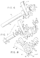
- Figure 6 is an isometric view of a second embodiment of a splitting tool according to the invention, as the wedge means would be aligned when the tool is impelled towards an object to be split.
- Figure 7 is an exploded view of the tool of Figure 6.
- Figure 8 is a transverse sectional view of the tool of Figure 6, taken along the line 8-8 in Figure 6.
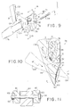
- Figure 9 is an exploded view of a third embodiment of a splitting tool according to the invention.
- Figure 10 is a transverse sectional view of the tool of Figure 9, taken along the lines 10-10 in Figure 9.
- Figure 11 is a partial longitudinal view of the tool of Figure 9, taken along the lines 11-11 in Figure 9.
- Splitting tool 10 comprises a handle 12 and a splitting head 14.
- Handle 12 is generally an elongated cylinder, but need not be exactly cylindrical. Thus, handle 12 may be tapered, or may be contoured much like a traditional ax handle. Handle 12 may be fabricated of any suitable material, such as wood or any of a number of engineering polymers, although wood is preferred since wood is somewhat resilient and naturally absorbs some of the impact that would be transmitted to the arms of the user when swinging the tool against objects to be split.
- splitting head 14 may be mounted on any other convenient means for impelling head 14 toward an object being split, without departing from the invention.
- head 14 may be mounted on supports which permit it to be raised and then fall in guillotine-like fashion onto an object placed below head 14.
- Splitting head 14 comprises a pair of wedge means 16 and 18 fitted together in interdigitated fashion.
- Wedge means 16 and 18 are identical and comprise a plurality of individual wedge fingers 20 which are spaced apart by a distance about equal to their width.
- the wedge fingers 20 of one wedge means are received in the spaces between the wedge fingers of the other wedge means, such that the wedge fingers 20 of both wedge means are interdigitated.
- Each wedge means 16 and 18 has a generally centrally-located circular bore 22 for mounting on handle 12.
- the inner diameter of bore 22 is preferably slightly greater than the outer diameter of handle 12 so that each wedge means 16 and 18 is freely rotatable about the central axis of handle 12.
- both wedge means 16 and 18 rotate freely about handle 12
- the invention includes a tool 10 in which only one wedge means rotates about the handle while the other remains fixed to the handle.
- Wedge means 16 and 18 are retained on handle 12 by retaining rings 24 and washers 26 seated in circumferential grooves 28 on handle 12.
- Wedge means 16 and 18 may be conveniently cast in one piece from a suitably hard and durable material, e.g., steel, such that cross-members 30 and 32 are integral with wedge fingers 20.
- wedge means 16 and 18 may be machined from a block of material, or may comprise individually-fabricated fingers and cross-members suitably joined together such as by welding. It should also be noted that, although three wedge fingers are illustrated in the figures, the exact number of fingers is not crucial to the invention. If desired, as few as one wedge finger 20 on each wedge means may be used.
- Each wedge finger terminates at one end in a front edge 34 for striking and penetrating the object to be split by tool 10.
- front edge 34 is preferably tapered to a keen cutting edge, much as a conventional ax blade would be tapered.
- each wedge finger 20 widens to a lobe 36.
- most of the mass of the wedge fingers 20 is located in lobe 36, and preferably is located rearward of handle 12 (rearward being understood to be in a direction behind front edge 34 as the tool is swung at the object).
- each wedge finger 20 will have a center of mass M located in the lobe and offset from the central axis of handle 12. This construction enables wedge means 16 and 18 to rotate freely about handle 12 when the tool is swung at an object to be split, as will now be described.
- the splitting tool 10 is grasped by the handle and swung, in the manner of an ax, at the log. Tool 10 is held so that the front edges 34 of wedge fingers 20 will strike the log and penetrate it. As will be understood, when the tool 10 is swung in this manner it will be raised over the user's head or shoulder and then brought rapidly down on the log. For a brief period, the tool is stationary after it is raised and before it is brought down on the log. As the tool is rapidly brought down against the log, it is accelerated from a rest position. Applying the principles of Newtonian mechanics, the rapid acceleration of the tool will result in a force being applied to all parts of the tool, including the wedge means 16 and 18.
- the wedge means 16 and 18 can be visualized as point masses located at their respective centers of mass M, and hence the forces on the wedge means 16 and 18 can be visualized as acting on the wedge means 16 and 18 at points M.
- the direction of this force will be opposite to the direction of movement of the tool; that is, the force will be in a rearward direction. Since wedge means 16 and 18 are mounted for rotation about handle 12, this force will create a force moment about the central axis of handle 12. This force moment is illustrated by the arcuate arrows F in Figure 2.
- the force moments F shown in Figure 2 have a clockwise sense with respect to wedge means 18 and a counterclockwise sense with respect to wedge means 16. (The force moments will have opposite senses since the respective centers of mass of wedge means 16 and 18 are on opposite sides of the central axis of handle 12.) The resulting force moment F acting on wedge means 18 thus tends to rotate wedge means 18 in the clockwise direction, and the resulting force moment F acting on wedge means 16 tends to rotate wedge means 16 in the counterclockwise direction.
- the respective cross-members 30 on wedge means 16 and 18 act as stops to limit the rotation of wedge means 16 and 18 due to the force moments so that the front edges 34 of wedge fingers 20 will be generally aligned in a common plane, as shown in Figures 1 and 2. (In Figure 2, the common plane is perpendicular to the plane of the figure.) This gives tool 10 a substantially continuous cutting edge made up of the front edges 34 of wedge fingers 20.
- splitting forces generally perpendicular to the common plane of front edges 34 are applied to the log to be split. That is, as the wedge fingers 20 rotate past each other after the splitting head 14 strikes the log, they apply splitting forces F'' to the log, as shown by the horizontal arrows in Figure 5.
- the splitting forces are generally, although not exactly, perpendicular to the common plane, so that virtually all of the energy input to tool 10 in striking the log is available for splitting.
- splitting tool 40 comprises a handle 42 and a splitting head 44.
- Handle 42 is generally an elongated cylinder, but need not be exactly cylindrical, and may be tapered or contoured like a traditional ax handle.
- Splitting head 44 comprises a pair of wedge means 46 and 48.
- Wedge means 46 comprises a wedge finger and a generally centrally-located circular bore 52 for mounting on handle 42. The diameter of bore 52 is preferably slightly greater than the outer diameter of handle 42 so that wedge means 46 is freely rotatable with respect to handle 42.
- Wedge means 46 includes a pawl 54, which acts as a stop to limit the rotation of wedge means 46, as will be described in more detail below.
- Wedge means 48 comprises a pair of individual wedge fingers 56 which are spaced apart by a distance about equal to the width of wedge finger 50, so that wedge means 46 is received within the space and wedge finger 50 will interdigitate with wedge fingers 56.
- wedge means 48 includes a generally centrally-located circular bore 58, which aligns with bore 52 in wedge means 46, for mounting on handle 42.
- the inner diameter of bore 58 is preferably the same as that of bore 52, i.e., preferably slightly greater than the outer diameter of handle 42 so that wedge means 48 is freely rotatable with respect to handle 42.
- only one of wedge means 46 and 48 need rotate, while the other may remain fixed with respect to handle 42. Both wedge means 46 and 48 are retained on handle 42 by retaining rings 58 and washers 60 seated in circumferential grooves 62 on handle 42.
- Each wedge finger 50 and 56 terminates at one end in a front edge 64 for striking and penetrating the object to be split by tool 40.
- front edge 64 is preferably tapered to a keen cutting edge, much as a conventional ax blade would be tapered.
- each wedge means 46 and 48 includes a lobe 66.
- lobe 66 bridges both wedge fingers 56, so that lobe 66 is a single piece.
- most of the mass of the wedge means 46 and 48 is located in lobes 66 and is located rearward of handle 42.
- each wedge means 46 and 48 will have a center of mass M' located in lobe 66 and offset from the central axis of handle 42, so that the wedge means 46 and 48 may rotate freely about handle 42 when tool 40 is swung at an object to be split.
- splitting forces generally perpendicular to the common plane of front edges 64 are applied to the log to be split. That is, as the wedge fingers 50 and 56 rotate past each other after the splitting head 44 strikes the object, they apply splitting forces F'' to the object, as shown by the horizontal arrows in Figure 8.
- the splitting forces are generally, although not exactly, perpendicular to the common plane so that substantially all of the energy with which tool 40 is swung goes to splitting the object.
- Tool 74 while embodying all of the features of the invention, bears a closer resemblance to a traditional ax.
- Tool 74 comprises a handle 76 and a splitting head 78.
- Handle 76 is contoured much like a traditional ax handle, and has a neck 80 at one end to which splitting head 78 is attached.
- Splitting head 78 comprises wedge means 82 and 84.
- Wedge means 82 comprises an eye 86 therethrough which receives neck 80 of handle 76.
- Handle 76 is secured to wedge means 82 by means of a serrated locking wedge 88, which is driven into neck 80 of handle 76 through eye 86, just as a conventional ax head is attached to a handle.
- wedge means 82 is fixed relative to the handle, just like a conventional ax head.
- Wedge means 82 includes a pair of wedge fingers 90 spaced apart by a shank 92.
- Wedge means 82 may conveniently be cast of a suitably hard and durable material such as steel, or may be machined from a single block or fabricated of individual parts suitably joined together, such as by welding.
- Wedge means 84 is received in the space between wedge fingers 90 on wedge means 82.
- the width of wedge means 84 is just slightly less than the gap between wedge fingers 90.
- wedge means 84 is rotatably attached to wedge means 82 by means of a threaded bolt 94, which passes through bores 96 in wedge fingers 90 and an aligning bore 98 in wedge means 84. Bores 96 and 98 are all substantially coaxial. Bores 96 are preferably threaded to threadedly receive bolt 94. Bore 98 has an inner diameter preferably slightly larger than the diameter of bolt 94 and is not threaded, so that wedge means 84 may rotate freely about the bolt. Bolt 94 is secured in place by a locking nut 100.
- the outer faces of wedge fingers 90 may be provided with counterbores 102 around bores 96, in order to recess the head of bolt 94 and nut 100.
- Bolt 94 defines a pivot axis about which wedge means 84 may rotate relative to wedge means 82.
- Wedge means 84 and wedge fingers 90 terminate in front edges 104 and 106, respectively, for striking and penetrating an object to be split.
- front edges 104 and 106 are tapered to a keen cutting edge, just like a conventional ax blade.
- wedge means 84 widens to a lobe 108.
- most of the mass of wedge means 84 is located in lobe 108, behind the pivot axis defined by bolt 94.
- wedge means 84 will have a center of mass M'' located in lobe 108 and offset from the axis defined by bolt 94. This enables wedge means 84 to rotate freely about bolt 94 when tool 74 is swung at an object to be split.
- splitting tool 74 is grasped by handle 76 and swung, just like an ax, at the object to be split.
- wedge means 84 will tend to pivot in a clockwise direction, so that front edges 104 and 106 will align along a common plane, giving tool 74 a substantially continuous cutting edge made up of front edges 104 and 106.
- Wedge means 82 and 84 may be provided with opposing flats 110 and 112, respectively, which act as stops to limit clockwise rotation of wedge means 84 with respect to wedge means 82 and ensure that edges 104 and 106 remain in alignment for striking.
- wedge means 84 After splitting head 78 strikes the object, wedge means 84 will tend to rotate in the counterclockwise direction, and front edge 104 will tend to rotate past front edges 106 through their common plane. To limit counterclockwise rotation of wedge means 84, it may be provided with a pawl 114 which engages a corresponding stop surface 116 on wedge means 82. As wedge means 84 rotates after splitting head 78 strikes the object, it applies splitting forces F'' to the object, as shown by the horizontal arrows in Figure 10. The splitting forces are generally, although not exactly, perpendicular to the common plane, so that substantially all of the energy imparted to tool 74 in striking the object goes into splitting it.
- the splitting tool of the present invention does not require levers, springs, or contact between spreaders and the object in order to achieve rotation of the wedge means, and thus apply splitting forces to the object.
- the tool of the present invention achieves a high splitting efficiency by utilizing the natural movement of the tool and the application of basic principles of mechanics.
- the tool of the present invention attain a minimum degree of penetration of the object being split, as do prior art splitters, in order to actuate the wedge fingers.
- the tool of the present invention need not be swung very hard against an object in order to be effective, which, in turn, means that the tool of the present invention is less tiring to use.
Landscapes
- Life Sciences & Earth Sciences (AREA)
- Engineering & Computer Science (AREA)
- Forests & Forestry (AREA)
- Wood Science & Technology (AREA)
- Mechanical Engineering (AREA)
- Liquid Crystal (AREA)
- Eye Examination Apparatus (AREA)
- Spectrometry And Color Measurement (AREA)
- Knives (AREA)
- Sawing (AREA)
- Processing Of Stones Or Stones Resemblance Materials (AREA)
Claims (3)
- Spaltgerät (10; 40; 74) mit einem an einem Stiel (12; 42; 76) angebrachten Spaltkopf (14; 44; 78), der wenigstens zwei relativ rotierbare Keile (16; 18; 46, 48; 82, 84) aufweist, wobei wenigstens einer der Keile auch gegenüber dem Stiel (12; 42; 76) frei rotierbar ist und jeder Keil eine Vorderkante (34: 64; 104, 106) zum Auftreffen auf und zum Eindringen in ein zu spaltendes Objeket aufweist und der oder jeder frei rotierbare Keil mit einem Flügel (16, 18; 46, 48; 108) rückseitig von der Vorderkante versehen ist und ein Massenmittelpunkt (M; M'; M'') sich in diesem Flügel und gegenüber der Rotationsachse des frei rotierbaren Teiles versetzt befindet, um ein Drehmoment um diese Achse zu erzeugen, dadurch gekennzeichnet, daß Anschlagmittel (30, 32; 68, 70; 110, 112) vorgesehen sind derart, daß die Flügel so angeordnet sind, daß sie außer Berührung mit dem Objekt bleiben, und daß das Drehmoment oder die Drehmomente in einem ersten Rotationssinn die Tendenz hat bzw. haben, die Vorderkanten jedes Keiles in einer gemeinsamen Ebene auszurichten, wenn der Spaltkopf in Richtung auf das Objekt vorgetrieben wird, und in einem zweiten und entgegengesetzten Rotationssinn die Tendenz hat bzw. haben, die Vorderkanten der Keile zu trennen, wenn der Spaltkopf auf dem Objekt auftrifft, wodurch Spaltkräfte an dem Objekt zur Einwirkung in Richtungen gebracht werden, die allgemein senkrecht zu der gemeinsamen Ebene verlaufen.
- Spaltgerät nach Anspruch 1, dadurch gekennzeichnet, daß ein erster Keil (18; 48; 82) ein Paar in einem Abstand voneinander angeordneter Keilfinger (20; 56; 90) aufweist, von denen jeder mit einer Vorderkante (34; 64; 106) versehen ist, und die Vorderkanten des ersten Keiles im wesentlichen in derselben Ebene sich befinden, die die gemeinsame Ebene definiert, und ein zweiter Keil (16; 46: 84) rotierbar in dem Raum zwischen den Keilfingern des ersten Keiles angeordnet ist.
- Spaltgerät nach Anspruch 1, dadurch gekennzeichnet, daß der Spaltkopf (78) einen Zwischenraum in seiner Schneidkante aufweist und ein rotierbarer Keil (84) zwecks Rotationsbewegung in der Zwischenraum angebracht ist.
Priority Applications (1)
| Application Number | Priority Date | Filing Date | Title |
|---|---|---|---|
| AT91305426T ATE101549T1 (de) | 1990-08-03 | 1991-06-14 | Spaltgeraet. |
Applications Claiming Priority (2)
| Application Number | Priority Date | Filing Date | Title |
|---|---|---|---|
| US07/562,775 US5020225A (en) | 1990-08-03 | 1990-08-03 | Splitting tool |
| US562775 | 2000-05-02 |
Publications (2)
| Publication Number | Publication Date |
|---|---|
| EP0469707A1 EP0469707A1 (de) | 1992-02-05 |
| EP0469707B1 true EP0469707B1 (de) | 1994-02-16 |
Family
ID=24247726
Family Applications (1)
| Application Number | Title | Priority Date | Filing Date |
|---|---|---|---|
| EP91305426A Expired - Lifetime EP0469707B1 (de) | 1990-08-03 | 1991-06-14 | Spaltgerät |
Country Status (4)
| Country | Link |
|---|---|
| US (1) | US5020225A (de) |
| EP (1) | EP0469707B1 (de) |
| AT (1) | ATE101549T1 (de) |
| DE (1) | DE69101195T2 (de) |
Families Citing this family (8)
| Publication number | Priority date | Publication date | Assignee | Title |
|---|---|---|---|---|
| FI109184B (fi) * | 2001-02-07 | 2002-06-14 | Heikki Kaernae | Kirves |
| US9808946B2 (en) | 2009-07-21 | 2017-11-07 | Dana Stone Clarke | Apparatus for splitting wood into kindling |
| US8424212B2 (en) * | 2009-07-21 | 2013-04-23 | Dana S. Clarke | Apparatus for splitting wood into kindling |
| DE102012105098A1 (de) * | 2012-06-13 | 2013-12-19 | Maschinenbau Krumscheid Gmbh | Orthogonal wirkender Spaltkeil |
| FI127232B (en) | 2016-04-18 | 2018-02-15 | Heikki Kaernae | AX |
| CN106305339B (zh) * | 2016-08-17 | 2020-09-11 | 苏州朝霞生物科技有限公司 | 一种可开合的工业伐木刀 |
| US11667046B2 (en) * | 2019-07-03 | 2023-06-06 | Peter Washington | Apparatus and method for splitting logs |
| USD1053692S1 (en) * | 2022-06-07 | 2024-12-10 | Planemill Finland Ltd Oy | Axe head |
Family Cites Families (11)
| Publication number | Priority date | Publication date | Assignee | Title |
|---|---|---|---|---|
| US443581A (en) * | 1890-12-30 | Wedge | ||
| SU443758A2 (ru) * | 1973-02-20 | 1974-09-25 | Львовский Лесотехнический Институт | Рабочий орган для механических дровокольных станков |
| US3865163A (en) * | 1974-05-15 | 1975-02-11 | Charles M Root | Splitter head with spreader arms |
| US4044808A (en) * | 1976-05-20 | 1977-08-30 | Kolonia Robert A | Splitting assembly |
| US4300606A (en) * | 1979-02-02 | 1981-11-17 | Branson Johnny R | Wood splitting axe |
| US4440205A (en) * | 1980-08-08 | 1984-04-03 | Alltrade, Inc. | Wedge and axe head |
| US4383562A (en) * | 1980-08-28 | 1983-05-17 | Hockman Mark E | Splitting device |
| US4372360A (en) * | 1981-07-29 | 1983-02-08 | Eichlin Harold E | Splitting axe |
| US4412572A (en) * | 1981-08-19 | 1983-11-01 | Clark Thomas A | Splitting axe |
| US4381809A (en) * | 1981-12-02 | 1983-05-03 | Kenjorski Arthur A | Splitting ax |
| CA1166555A (en) * | 1984-02-21 | 1984-05-01 | Stephen Aderneck | Double action off-centered mass kinetic prying wood splitting maul |
-
1990
- 1990-08-03 US US07/562,775 patent/US5020225A/en not_active Expired - Fee Related
-
1991
- 1991-06-14 EP EP91305426A patent/EP0469707B1/de not_active Expired - Lifetime
- 1991-06-14 DE DE69101195T patent/DE69101195T2/de not_active Expired - Fee Related
- 1991-06-14 AT AT91305426T patent/ATE101549T1/de not_active IP Right Cessation
Also Published As
| Publication number | Publication date |
|---|---|
| ATE101549T1 (de) | 1994-03-15 |
| DE69101195D1 (de) | 1994-03-24 |
| EP0469707A1 (de) | 1992-02-05 |
| DE69101195T2 (de) | 1994-05-26 |
| US5020225A (en) | 1991-06-04 |
Similar Documents
| Publication | Publication Date | Title |
|---|---|---|
| EP0469707B1 (de) | Spaltgerät | |
| US4926558A (en) | Axe maul apparatus | |
| US5871204A (en) | Hand tool with adjustable head | |
| CA2381762C (en) | A light-weight striking tool | |
| CA1062128A (en) | Splitting assembly | |
| DE1939262C2 (de) | Schlagvorrichtung | |
| US4175601A (en) | Hand-held wedge tool for splitting wood | |
| US5107911A (en) | Log splitting device | |
| US4300606A (en) | Wood splitting axe | |
| US3973607A (en) | Debarking tool | |
| US4467851A (en) | Splitting device | |
| US4252166A (en) | Log splitter | |
| EP0047108B1 (de) | Spaltgerät | |
| US6167929B1 (en) | Method and apparatus for profiling a log | |
| GB2097719A (en) | Splitting device | |
| CA1166555A (en) | Double action off-centered mass kinetic prying wood splitting maul | |
| US3858465A (en) | Wrench | |
| US3585838A (en) | Bucking bar | |
| US5921300A (en) | Log-splitting device | |
| US5012567A (en) | Impact tool | |
| US5419048A (en) | Cutting tool | |
| US5971044A (en) | Tool with parallel corners for splitting wood | |
| DE69512796T2 (de) | Handwerkzeug zum spalten von holz | |
| DE202010016685U1 (de) | Schlagwerkzeug | |
| DE934579C (de) | Insbesondere fuer Schlagwerkzeuge bestimmte Vorrichtung zum Umsetzen einer hin- und hergehenden Bewegung in eine kreisende Bewegung |
Legal Events
| Date | Code | Title | Description |
|---|---|---|---|
| PUAI | Public reference made under article 153(3) epc to a published international application that has entered the european phase |
Free format text: ORIGINAL CODE: 0009012 |
|
| AK | Designated contracting states |
Kind code of ref document: A1 Designated state(s): AT BE CH DE DK ES FR GB GR IT LI LU NL SE |
|
| 17P | Request for examination filed |
Effective date: 19920416 |
|
| 17Q | First examination report despatched |
Effective date: 19920710 |
|
| GRAA | (expected) grant |
Free format text: ORIGINAL CODE: 0009210 |
|
| AK | Designated contracting states |
Kind code of ref document: B1 Designated state(s): AT BE CH DE DK ES FR GB GR IT LI LU NL SE |
|
| PG25 | Lapsed in a contracting state [announced via postgrant information from national office to epo] |
Ref country code: IT Free format text: LAPSE BECAUSE OF FAILURE TO SUBMIT A TRANSLATION OF THE DESCRIPTION OR TO PAY THE FEE WITHIN THE PRE;WARNING: LAPSES OF ITALIAN PATENTS WITH EFFECTIVE DATE BEFORE 2007 MAY HAVE OCCURRED AT ANY TIME BEFORE 2007. THE CORRECT EFFECTIVE DATE MAY BE DIFFERENT FROM THE ONE RECORDED.SCRIBED TIME-LIMIT Effective date: 19940216 Ref country code: NL Effective date: 19940216 Ref country code: CH Effective date: 19940216 Ref country code: BE Effective date: 19940216 Ref country code: DK Effective date: 19940216 Ref country code: AT Effective date: 19940216 Ref country code: SE Effective date: 19940216 Ref country code: GR Free format text: LAPSE BECAUSE OF FAILURE TO SUBMIT A TRANSLATION OF THE DESCRIPTION OR TO PAY THE FEE WITHIN THE PRESCRIBED TIME-LIMIT Effective date: 19940216 Ref country code: ES Free format text: THE PATENT HAS BEEN ANNULLED BY A DECISION OF A NATIONAL AUTHORITY Effective date: 19940216 Ref country code: LI Effective date: 19940216 Ref country code: FR Free format text: THE PATENT HAS BEEN ANNULLED BY A DECISION OF A NATIONAL AUTHORITY Effective date: 19940216 |
|
| REF | Corresponds to: |
Ref document number: 101549 Country of ref document: AT Date of ref document: 19940315 Kind code of ref document: T |
|
| REF | Corresponds to: |
Ref document number: 69101195 Country of ref document: DE Date of ref document: 19940324 |
|
| REG | Reference to a national code |
Ref country code: CH Ref legal event code: PL |
|
| PG25 | Lapsed in a contracting state [announced via postgrant information from national office to epo] |
Ref country code: LU Free format text: LAPSE BECAUSE OF NON-PAYMENT OF DUE FEES Effective date: 19940630 |
|
| EN | Fr: translation not filed | ||
| NLV1 | Nl: lapsed or annulled due to failure to fulfill the requirements of art. 29p and 29m of the patents act | ||
| PLBE | No opposition filed within time limit |
Free format text: ORIGINAL CODE: 0009261 |
|
| STAA | Information on the status of an ep patent application or granted ep patent |
Free format text: STATUS: NO OPPOSITION FILED WITHIN TIME LIMIT |
|
| 26N | No opposition filed | ||
| PG25 | Lapsed in a contracting state [announced via postgrant information from national office to epo] |
Ref country code: GB Effective date: 19950614 |
|
| GBPC | Gb: european patent ceased through non-payment of renewal fee |
Effective date: 19950614 |
|
| PGFP | Annual fee paid to national office [announced via postgrant information from national office to epo] |
Ref country code: DE Payment date: 19990624 Year of fee payment: 9 |
|
| PG25 | Lapsed in a contracting state [announced via postgrant information from national office to epo] |
Ref country code: DE Free format text: LAPSE BECAUSE OF NON-PAYMENT OF DUE FEES Effective date: 20010403 |