EP0469617B1 - Closed-loop feedback control system having an adaptive filter - Google Patents
Closed-loop feedback control system having an adaptive filter Download PDFInfo
- Publication number
- EP0469617B1 EP0469617B1 EP91112973A EP91112973A EP0469617B1 EP 0469617 B1 EP0469617 B1 EP 0469617B1 EP 91112973 A EP91112973 A EP 91112973A EP 91112973 A EP91112973 A EP 91112973A EP 0469617 B1 EP0469617 B1 EP 0469617B1
- Authority
- EP
- European Patent Office
- Prior art keywords
- filter
- motor
- motor speed
- signal
- reference signal
- Prior art date
- Legal status (The legal status is an assumption and is not a legal conclusion. Google has not performed a legal analysis and makes no representation as to the accuracy of the status listed.)
- Expired - Lifetime
Links
Images


Classifications
-
- H—ELECTRICITY
- H02—GENERATION; CONVERSION OR DISTRIBUTION OF ELECTRIC POWER
- H02P—CONTROL OR REGULATION OF ELECTRIC MOTORS, ELECTRIC GENERATORS OR DYNAMO-ELECTRIC CONVERTERS; CONTROLLING TRANSFORMERS, REACTORS OR CHOKE COILS
- H02P5/00—Arrangements specially adapted for regulating or controlling the speed or torque of two or more electric motors
-
- G—PHYSICS
- G05—CONTROLLING; REGULATING
- G05B—CONTROL OR REGULATING SYSTEMS IN GENERAL; FUNCTIONAL ELEMENTS OF SUCH SYSTEMS; MONITORING OR TESTING ARRANGEMENTS FOR SUCH SYSTEMS OR ELEMENTS
- G05B19/00—Programme-control systems
- G05B19/02—Programme-control systems electric
- G05B19/18—Numerical control [NC], i.e. automatically operating machines, in particular machine tools, e.g. in a manufacturing environment, so as to execute positioning, movement or co-ordinated operations by means of programme data in numerical form
- G05B19/19—Numerical control [NC], i.e. automatically operating machines, in particular machine tools, e.g. in a manufacturing environment, so as to execute positioning, movement or co-ordinated operations by means of programme data in numerical form characterised by positioning or contouring control systems, e.g. to control position from one programmed point to another or to control movement along a programmed continuous path
-
- H—ELECTRICITY
- H02—GENERATION; CONVERSION OR DISTRIBUTION OF ELECTRIC POWER
- H02P—CONTROL OR REGULATION OF ELECTRIC MOTORS, ELECTRIC GENERATORS OR DYNAMO-ELECTRIC CONVERTERS; CONTROLLING TRANSFORMERS, REACTORS OR CHOKE COILS
- H02P23/00—Arrangements or methods for the control of AC motors characterised by a control method other than vector control
- H02P23/16—Controlling the angular speed of one shaft
-
- G—PHYSICS
- G05—CONTROLLING; REGULATING
- G05B—CONTROL OR REGULATING SYSTEMS IN GENERAL; FUNCTIONAL ELEMENTS OF SUCH SYSTEMS; MONITORING OR TESTING ARRANGEMENTS FOR SUCH SYSTEMS OR ELEMENTS
- G05B2219/00—Program-control systems
- G05B2219/30—Nc systems
- G05B2219/41—Servomotor, servo controller till figures
- G05B2219/41166—Adaptive filter frequency as function of oscillation, rigidity, inertia load
-
- G—PHYSICS
- G05—CONTROLLING; REGULATING
- G05B—CONTROL OR REGULATING SYSTEMS IN GENERAL; FUNCTIONAL ELEMENTS OF SUCH SYSTEMS; MONITORING OR TESTING ARRANGEMENTS FOR SUCH SYSTEMS OR ELEMENTS
- G05B2219/00—Program-control systems
- G05B2219/30—Nc systems
- G05B2219/41—Servomotor, servo controller till figures
- G05B2219/41232—Notch filter
-
- G—PHYSICS
- G05—CONTROLLING; REGULATING
- G05B—CONTROL OR REGULATING SYSTEMS IN GENERAL; FUNCTIONAL ELEMENTS OF SUCH SYSTEMS; MONITORING OR TESTING ARRANGEMENTS FOR SUCH SYSTEMS OR ELEMENTS
- G05B2219/00—Program-control systems
- G05B2219/30—Nc systems
- G05B2219/41—Servomotor, servo controller till figures
- G05B2219/41344—Piezo, electrostrictive linear drive
-
- Y—GENERAL TAGGING OF NEW TECHNOLOGICAL DEVELOPMENTS; GENERAL TAGGING OF CROSS-SECTIONAL TECHNOLOGIES SPANNING OVER SEVERAL SECTIONS OF THE IPC; TECHNICAL SUBJECTS COVERED BY FORMER USPC CROSS-REFERENCE ART COLLECTIONS [XRACs] AND DIGESTS
- Y10—TECHNICAL SUBJECTS COVERED BY FORMER USPC
- Y10S—TECHNICAL SUBJECTS COVERED BY FORMER USPC CROSS-REFERENCE ART COLLECTIONS [XRACs] AND DIGESTS
- Y10S388/00—Electricity: motor control systems
- Y10S388/907—Specific control circuit element or device
- Y10S388/91—Operational/differential amplifier
-
- Y—GENERAL TAGGING OF NEW TECHNOLOGICAL DEVELOPMENTS; GENERAL TAGGING OF CROSS-SECTIONAL TECHNOLOGIES SPANNING OVER SEVERAL SECTIONS OF THE IPC; TECHNICAL SUBJECTS COVERED BY FORMER USPC CROSS-REFERENCE ART COLLECTIONS [XRACs] AND DIGESTS
- Y10—TECHNICAL SUBJECTS COVERED BY FORMER USPC
- Y10S—TECHNICAL SUBJECTS COVERED BY FORMER USPC CROSS-REFERENCE ART COLLECTIONS [XRACs] AND DIGESTS
- Y10S388/00—Electricity: motor control systems
- Y10S388/923—Specific feedback condition or device
- Y10S388/93—Load or torque
Definitions
- the present invention relates to a motor speed controller for suppressing the resonance generated in the driving of a load.
- the Japanese Patent publication JP-A-1-173396 discloses a speed controller for a motor comprising a notch filter for suppressing a natural frequency of the system. At the time of starting the motor, a detected rotational speed is stored in an arithmetic device. A further arithmetic device calculates the natural resonance frequency of the system, whereupon the constant of the notch filter is determined which eliminates the frequency.
- the Japanese Patent publication JP-A-1-304511 discloses a control apparatus for a mechanically driven machine such as robots, machine tools, etc.
- the control apparatus comprises means for detecting a change of mechanical condition of the machine and compensating calculator means responsive to the detecting means for calculating and outputting compensating data to make the machine move in accordance with input command data.
- the apparatus further comprises adapted filter means for suppressing frequency components close to the mechanical resonance frequency of the machine in response to the output data of the detecting means.
- motor 1 drives a load 4 via coupler 3.
- the torque of the motor 1 is controlled by torque controlling unit 8, which receives a new torque command ⁇ 2* from a notch filter 7.
- the notch filter 7 is used to filter a torque command ⁇ 1* output from operating/amplifying unit 6 so that any resonance appearing in the signal can be eliminated to produce the new torque command ⁇ 2*.
- the operating/amplifying unit 6 outputs the torque command ⁇ 1* as a deviation value ⁇ r *- ⁇ r , representing the difference between the speed command value ⁇ r * and a speed detection value ⁇ r .
- Subtractor unit 5 receives the speed command value ⁇ r * from the machine controller (not shown) and the detected speed ⁇ r from speed detector 2.
- the speed detection value ⁇ r output by the speed detector 2 is fed back to the motor speed controller. Then the operating/amplifying unit 6 operates and amplifies the deviation value ⁇ r * - ⁇ r entered from the subtracting unit 5 until the value is zero. The unit 6 outputs the result as the torque command value ⁇ 1*, which is then input to the torque controlling unit 8 via notch filter 7, and the motor 1 is speed-controlled to follow the speed command value ⁇ r * by the output signal of the torque controlling unit 8.
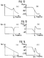
- Figs. 12(a) and 12(b) illustrate the transfer functions of the torque controlling unit 8 and motor 1.
- the figures indicate the relationship between frequency and gain, and between frequency and phase, respectively, wherein the peak of the gain exists at the frequency f p due to machine resonance.
- Figs. 13(a) and 13(b) illustrate the transfer functions of the notch filter 7 having a central frequency f c .
- Figs. 14(a) and 14(b) illustrate the functions after passing through the notch filter 7 to the motor 1 when the resonance frequency f p and the central frequency f c of the notch filter 7 have been adjusted to match each other.
- the peak of the gain due to the machine resonance in Fig. 12(a) and the notch of the gain of the notch filter 7 in Fig. 13(a) offset each other to suppress the machine resonance, thus eliminating the peak from the gain characteristic.
- the gain of the operating/amplifying unit 6 can be raised to enhance the response of the speed control system.
- the adjusted filter coefficient is fixed.
- the resonance frequency f p will not match the central frequency f c of the notch filter 7.
- the suppression of the resonance may not be achieved and the motor control system may become unstable.
- Figs. 15(a) and 15(b) illustrate the characteristics of transmission from the notch filter 7 to the motor 1 at a time when the notch filter 7 central frequency f c is lower than the machine resonance frequency f p .
- the peak of the resonance gain is not suppressed sufficiently and a phase delay value in the low frequency range is increased by the phase delay of the notch filter 7; thus, deteriorating the speed response characteristic, e.g., an overshoot increase.
- Figs. 16(a) and 16(b) illustrate the functions of the transmission from the notch filter 7 to the motor 1 at a time when the notch filter 7 central frequency f c is higher than the machine resonance frequency f p .
- the peak of the resonance gain is not suppressed sufficiently and the phase delay value in the neighborhood of the gain peak is greatly increased by the phase delay of the notch filter 7. This makes the speed control system unstable and may cause oscillation depending on the gain of the operating/amplifying unit 6, leading to a failure of control.
- the filter coefficient defining the characteristic of the notch filter 7 for suppressing the machine resonance may be manually adjusted by an operator on a machine-by-machine basis using an oscilloscope, an FFT analyzer, etc., so that the central frequency f c of the notch filter 7 matches the machine resonance frequency f p .
- This is done in accordance with the speed detection value ⁇ r of the motor 1 at a time when the speed command value ⁇ r * is provided from an external oscillator, or the like.
- this adjustment has the disadvantage that it requires measuring instruments, such as an oscillator and an oscilloscope, as well as much time and skill.
- a motor control circuit is disclosed in Japanese Patent Disclosure Publication No. 46184, wherein the resonance suppression circuit described above is applied to the take-up mechanism of a magnetic tape storage device.
- the resonance filter of the mechanical system varies according to the take-up position (value) of the tape.
- the control circuit is designed to overcome the disadvantage caused by a mismatch of the machine resonance frequency and a notch filter central frequency by changing the central frequency in three stages in accordance with an external signal corresponding to the changes of the machine resonance frequency.
- the central frequency is changed by switching a resistance element, comprising the notch filter, using a short-circuit switch.
- a positioning controller disclosed in the Japanese Patent Disclosure Publication No. 64599 is employed to position the magnetic head of a disc drive using a step motor.
- the positioning controller first detects the vibration of the magnetic head at a time when the magnetic head is moved step by step to vibration detecting tracks provided at specific positions of the inner and outer peripheries of the disc, to select a notch filter on a trial and error basis. This filter will suppress the amplitude of that vibration within a predetermined value from among a plurality of prepared notch filters different in frequency characteristic.
- the vibration characteristic of the step motor varying according to the track position is suppressed by selecting the appropriate notch filter for the tracks divided into three areas: inner periphery, middle and outer periphery. That is, the notch filter selected by the inner periphery vibration detecting track is chosen on the inner peripheral tracks, the notch filter selected by the outer periphery vibration detecting track is chosen on the outer peripheral tracks, and the notch filter representing the characteristic midway between the inner periphery notch filter and the outer periphery notch filter is chosen for the middle tracks.
- a motor speed controller is provided as defined in claim 1.
- Embodiments of the invention are given in claims 2 to 6.
- a filter coefficient setting unit operates to determine a filter coefficient for limiting the passage of the frequency component, and outputs the result to a main filter inserted in any position of the system ranging from the output end of a speed detecting unit to the input end of a torque controlling unit, said main filter limiting the passage of the frequency component in accordance with said filter coefficient entered.
- a reference signal generating unit receives a speed command value and outputs a reference signal having the predetermined bandwidth.
- the adaptive filter receives the reference signal output by said reference signal generating unit and the speed detection value output by a speed detecting unit, operates on the filter coefficient for limiting the passage of the frequency component in accordance with said frequency component superimposed on said speed detection value, and then outputs the result to the main filter.
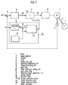
- Fig. 1 is a block diagram of a motor speed controller according to one embodiment of the present invention.
- Fig. 2 is a block diagram of the motor speed controller illustrating a variation of position of the adaptive filter in the main feedback loop according to another embodiment of the present invention.
- Figs. 3 and 4 are block diagrams of a speed controller controlling the speed of a load.
- Fig. 5 is a block diagram of a motdr speed controller according to another embodiment of the present invention.
- Fig. 6 is a block diagram illustrating the basic configuration of an adaptive filter.
- Figs. 7(a) to 7(e) and Figs. 8(a) to 8(c) are graphs indicating the power spectra of various parts and the frequency characteristic of the adaptive filter 16 in the embodiments of the present invention.
- Fig. 9 is a block diagram illustrating one embodiment of the reference signal generating unit 13.
- Fig. 10 is a graph representing the response waveforms of parts of the embodiment shown in Fig. 5.
- Fig. 11 is a block diagram illustrating a motor speed controller known in the art.
- Figs. 12(a) and 12(b) to Figs. 16(a) and 16(b) are charts representing the transmission functions of the elements in Fig. 11.
- Figs. 17 - 19 are flowcharts indicating the processing which takes place in a software implementation of Figs. 1 and 5;
- Fig. 20 illustrates an application to a fine-motion table using a piezo-actuator.
- Fig. 1 is a block diagram of a motor speed controller in accordance with one embodiment of the present invention.
- Fig. 1 illustrates a main filter 9 provided for limiting the passage of a frequency component in accordance with an entered filter coefficient f output from a filter coefficient setting unit 10.
- the block representing the filter coefficient setting unit 10 has a high-pass filter 12 provided for passing a frequency component higher than a predetermined frequency in the same region as an entered speed detection value ⁇ r output by a speed detector 2.
- the setting unit 10 further includes a reference signal generating unit 13, adding unit 15, and an adaptive filter 16.
- the reference signal generating unit 13 outputs a reference signal r having frequency components less than the predetermined frequency. This output is sent to adding unit 15 and adaptive filter 16.
- the high-pass filter 12 passes a signal including a resonance frequency component d received from the detector 2.
- the adding unit 15 receives the high-pass filter output and adds it to the reference signal r output from the signal generating unit 13.
- the resultant signal x is output to adaptive filter 16.
- the adaptive filter 16 then, operates on the filter coefficient f to limit the passage of the frequency component d, and outputs the result to main filter 9. It will be appreciated that where the main filter 9 and adaptive filter 16 employ plural coefficients, one or more coefficients may be subject to operation/variation in accordance with the invention. In this specification, for purposes of clarity, the singular term "filter coefficient" is consistently employed, but should be interpreted as covering both the singular and plural cases.
- Fig. 6 is a block diagram illustrating the basic configuration of the adaptive filter 16 having a filter 17 and a filter coefficient adjusting unit 19 for adjusting the filter coefficient of the filter 17.
- Figs. 7(a), 7(b), 7(c), 7(d) and 7(e) indicate the power spectra of the reference signal r, the signal d, input x, output y, and deviation e before adjustment of the filter coefficient f, respectively.
- Figs. 8(a), 8(b) and 8(c) indicate the power spectrum of the output y after adjustment of filter coefficient f, the deviation e, and the frequency characteristic of the filter 17, respectively.
- Fig. 9 is a block diagram illustrating one embodiment of the reference signal generating unit 13, having a random noise generating circuit 30, and a low-pass filter 31 which outputs the reference signal r.
- the cut-off frequency of the high-pass filter 12 in the filter coefficient setting unit 10 has been set to a speed control bandwidth f b .
- the high-pass filter 12 receives a motor speed ⁇ r (i.e. , speed detection value output by the speed detection unit 2) and outputs a machine resonance frequency component d included in that speed ⁇ r .
- the speed control bandwidth f b includes a frequency band at which the gain of a closed-loop transmission function ranging from the speed command to the speed of the motor 1 to be controlled is 1/ 2 times that of a dc gain.
- the speed control bandwidth f b is ordinarily set to less than 1/3 to 1/2 of the machine resonance frequency f p .
- the reference signal generating unit 13 generates the reference signal r including the same frequency components as the speed control bandwidth f b .
- the adder 15 adds the high-pass filter 12 output d and the reference signal r and outputs a signal x.
- the adaptive filter changes its own characteristic to output the most appropriate signal in accordance with the input signal applied; i.e., the filter changes its characteristic according to the quality of the input signal.
- the adaptive filter 16 adjusts its own filter coefficient serially so that its output y is most approximated to the target signal, i.e., reference signal r, in response to the input x.
- the input x includes the reference signal r and the vibration component d caused by machine resonance.
- the adaptive filter 16 adjusts its own filter coefficient to become a filter which passes the component of the frequency band that the reference signal r has, while suppressing other frequency components, here the component d due to machine resonance (i.e., it becomes a notch filter of which the central frequency f c matches the machine resonance frequency f p ).
- the filter coefficient of the main filter 9 is set to the same value as that of the adaptive filter 16 by the signal therefrom so as to have the characteristic of a notch filter.
- the main filter 9 is automatically adjusted to have a characteristic which suppresses the machine resonance frequency component which is the source of vibration due to machine resonance included in the output ⁇ 1* of the operating/amplifying unit 6.
- the input of the adaptive filter 16 is the vibration component d and the target signal is zero (i.e., r is zero)
- a filter which suppresses the vibration component due to machine resonance would in principle be generated according to the operation principle of the adaptive filter 16.
- the filter may have a frequency characteristic which cuts off all frequency components, and it is not ensured that the filter will provide the desired characteristic of-passing the frequency component up to the speed control bandwidth and suppressing the machine resonance frequency component.
- the optimum input of the adaptive filter 16 is the signal x which is the sum of non-zero reference signal r and the vibration component d.
- the filter 17 receives and filters the signal x, and the filter coefficient adjusting unit 19 adjusts the filter coefficient of the filter 17 to reduce the deviation e between the reference signal r and the filter output y output by subtracting unit 18, so that the output y is most approximated to the target signal, i.e., reference signal r.
- a finite impulse response (FIR) filter e.g., a transversal filter or a tapped delay line filter
- IIR infinite impulse response
- a least mean square (LMS) algorithm In the filter coefficient adjusting unit 19, a least mean square (LMS) algorithm, a recursive least square (RLS) algorithm, or the like, can be used.
- LMS least mean square
- RLS recursive least square
- These algorithms are also digital processing techniques and can be-employed with a microprocessor. The operation of, for example, the LMS algorithm will be described briefly.
- the square of the deviation e has a curved surface like a bowl in an (n + 1)-dimensional space with respect to the filter coefficient f and has a single minimum point.
- the LMS algorithm adjusts the filter coefficient at the next sampling by subtracting a variation value proportionate to the gradient of the bowl-shaped curved surface from the filter coefficient at the current sampling in order to converge the square of the deviation e on said minimum point.
- the cut-off frequency of the low-pass filter 31 (Fig. 9) included in the reference signal generating unit 13 is set to the speed control bandwidth f b . Consequently, the power spectrum of the reference signal r has a characteristic of attenuating above the speed control bandwidth f b , as shown in Fig. 7(a), and includes the frequency component up to the speed control bandwidth f b , but does not include the machine resonance frequency component.
- the power spectrum of the high-pass filter 12 output d has a peak at the machine resonance frequency f p , as shown in Fig. 7(b).
- the power spectrum of the signal x i.e ., the sum of the high-pass filter 12 output d and the reference signal r
- the input x of the filter 17 in the adaptive filter 16 includes the reference signal r, which includes the frequency component up to the speed control bandwidth f b
- the high-pass filter 12 output d which is the vibration component due to the machine resonance
- the power spectrum of the output y before filter coefficient adjustment has a waveform similar to the power spectrum of the input x, as shown in Fig. 7(d). Accordingly, the power spectrum of the deviation e between the reference signal r and the output y corresponds to that of the signal d in Fig.
- the main filter 9 is automatically adjusted to be a notch filter of which central frequency f c matches the machine resonance frequency f p .
- the main filter 9 need not be otherwise adjusted to suppress the machine resonance.
- the aforementioned adjustment of the filter coefficient f is made to allow automatic follow-up to the change in machine resonance frequency f p , thereby eliminating the possibility of unstable speed control.
- Fig. 2 is a block diagram of a motor speed controller according to another embodiment of the present invention, wherein the numerals used in Fig. 1 identify identical parts.
- Fig. 1 is different from Fig. 2 in that the main filter 9 of Fig. 2 receives the speed detection value ⁇ r of the motor 1 detected by the speed detector 2.
- the main filter 9 filters and outputs the speed detection value ⁇ r1
- the operating/amplifying unit 6 receives the deviation between the speed command value ⁇ r *, i.e ., the output of the subtracter 5, and the output ⁇ r1 of the main filter 9.
- the unit 6 outputs to the torque controlling unit 8 the torque command value ⁇ 1* which will reduce that deviation ⁇ r * - ⁇ r1 .
- the main filter 9 receives the filter coefficient f output by the filter coefficient setting unit 10 and is automatically adjusted to be a notch filter which suppresses the machine resonance frequency component. Therefore, the machine resonance frequency component is removed from ⁇ r1 and there is no possibility that after comparison with the speed command value ⁇ r * by the subtracter 8, ⁇ r1 will be amplified by the operating/amplifying unit 6 and cause vibration.
- Fig. 3 is a block diagram of a motor speed controller according to an arrangement, wherein a speed detector 2A is provided for detecting the speed ⁇ r of the load 4 (as opposed to the detection of speed of the motor achieved in the previous embodiments).
- the arrangement shown in Fig. 3 performs similar operation and has a similar effect to the one illustrated in Fig. 1, except that the speed detector 2A is provided in the load 4 for detecting and controlling the speed of the load 4.
- Fig. 4 is a block diagram of a motor speed controller according to another arrangement.
- the arrangement shown in Fig. 4 performs similar operation and produces a similar result as the one illustrated in Fig. 2, except that the speed detector 2A is provided in the load 4 for detecting and controlling the speed of the load 4.
- Fig. 5 is a block diagram of a motor speed controller according to another embodiment of the present invention, comprising a filter coefficient setting unit 11 and reference signal generating unit 14.
- the filter coefficient setting unit 11 is different from the filter coefficient setting unit 10 (shown in Fig. 1) in that the reference signal generating unit 14 receives the speed command value ⁇ r * and generates the reference signal r having almost the same bandwidth f b as that of the speed control system in response to the speed command value ⁇ r *.
- the adaptive filter 16 outputs the filter coefficient f in response to the input of said reference signal r and the speed detection value ⁇ r .
- the speed controller is substantially the same in configuration and operation as the one shown in Fig. 1.
- Fig. 10 shows response waveforms of the reference signal r, the motor speed ⁇ r , the output y of the adaptive filter 16, shown in Fig. 6, and the deviation e between the reference signal r and the output y, which are obtained at a time when the speed command value ⁇ r * is changed.
- the motor speed detecting value ⁇ r overlaps (is superimposed on) a response component to the speed command value ⁇ r * and a vibration component due to the machine resonance independent of that response component.
- the reference signal ⁇ r Since the reference signal ⁇ r is pre-adjusted as described previously to be in almost the same bandwidth as that of the speed control system, the reference signal r has almost the same waveform as that of the response component of the motor speed ⁇ r (excluding the reference value and the vibration component), as can be seen by comparing indicated by the waveforms of ⁇ r and r. As indicated by the waveform y, the output y of the adaptive filter 16 has a similar waveform to that of ⁇ r before the filter coefficient f is adjusted. Hence, the waveform of the deviation e between the reference signal r and the output y develops a waveform equivalent to the vibration component included in the motor speed ⁇ r .
- the filter coefficient adjusting unit 19 (Fig. 6) adjusts the filter coefficient f sequentially to reduce the deviation e so that the output y is approximated to the reference signal r. Accordingly, since the filter 17 has the characteristic of a notch filter which only suppresses the vibration component caused by machine resonance at the time when the deviation e is fully reduced after the adjustment of the filter coefficient f, the vibration component disappears from the motor speed ⁇ r and the output y. Furthermore, because the filter coefficient f of the main filter 9 is set to the same value as that of the filter 17 in the adaptive filter 16, the main filter 9 is automatically adjusted to be a notch filter of which central frequency f c matches the machine resonance frequency f p . Thus, the main filter 9 is automatically adjusted to suppress the machine resonance. Moreover, if the machine resonance frequency f p has changed, the aforementioned adjustment process is repeated so that the main filter 9 is automatically adjusted to have a notch filter characteristic corresponding to the machine resonance frequency f p .
- the reference signal generating unit 14 has a first order lag element of a time constant T1 represented by a transmission function in expression (1).
- T1 may be set so that the reference signal r has almost the same response in the bandwidth of the speed control system as the speed command value ⁇ r *.
- r 1 1+ sT 1 ⁇ r * where s is a differential operator.
- the first order lag element may be replaced by a second order lag element or the like which has been adjusted to have almost the same response to the speed control.
- the cut-off frequency of the low-pass filter 31 set to the speed control bandwidth f b in the block diagram of the reference signal generating unit 13 may be defined between f b and f p because any frequency component less than the machine resonance frequency f p may be included in the reference signal r.
- the high-pass filter 12 of which cut-off frequency has been set to the speed control bandwidth may be a band-pass filter, or the like, that has a characteristic where the low-range cut-off frequency has been set in the vicinity of the speed control bandwidth and the high-range cut-off frequency has been set to a higher value than the machine resonance frequency. This is because the machine resonance frequency component included in the speed ⁇ r of the motor 1, or the load 4, may be mainly detected by the high-pass filter 12.
- the random noise generating unit 30 may be replaced by a rectangular wave generating circuit or a triangular wave generating circuit, in which case harmonic components included in the rectangular wave or the triangular wave should be set so that many harmonic components are included at less than the cut-off frequency of the low-pass filter 31.
- the torque controlling unit 8 may be directly controlled by, for example, a current, a voltage of a magnetic flux of the motor 1, or a combination of the two if that controls the torque of the motor 1.
- the output of the operating/amplifying unit 6 need not indicate the torque directly and may be, for example, a current, a voltage, a magnetic flux, or the like, of the motor 1 if such controls the torque of the motor 1.
- the shaft directly connecting the motor 1 and the load 4 may be replaced by gears, a belt and pulleys, a ballscrew and nuts, or a combination of such elements.
- the shaft of the motor 1 may be regarded as a coupler, and if the rigidity of the load 4 is small, the load 4 may be regarded as comprising a coupler to a new load.
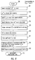
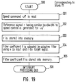
- Fig. 17 indicates an operation flowchart with the exception of the operation of the filter coefficient setting units 10 and 11 shown in Figs. 1 and 5, respectively.
- the filter coefficient f Since the filter coefficient f is operated on, stored into the memory (not illustrated), and updated serially by the execution of the operation shown in Fig. 18 or 19, the filter coefficient f is read from memory at step 107 and filtering is executed at step 108.
- Fig. 20 illustrates an embodiment as applied to a fine-motion table positioning device employing a piezo-actuator for use with semiconductor equipment, etc.
- a piezo-actuator 101 is fixed at one end and secured to a fine-motion table 102 at the other end.
- the piezo-actuator 101 stretches in the x direction in accordance with a voltage applied by a drive amplifier 100 to drive the fine-motion table 102 supported by a flexible support rod 103 and a workpiece mounted thereon.
- the displacement x of the fine-motion table 102 is detected and compared with a command value x* by a displacement detector 105 and a voltage command V1* is output by operation/amplifying unit 6 so that their deviation is zeroed.
- V1* is filtered by a main filter 9 and output to the drive amplifier 100 as a new voltage command V2*.
- the fine-motion table 102 is supported by the flexible support rod 103 to avoid the problem of friction which influences positioning accuracy.
- said flexible support rod 103, fine-motion table 102, and workpiece constitute a machine resonance system
- an attempt to position the fine-motion table 102 on a high-speed/rapid response basis for improved production efficiency causes vibration to occur due to machine resonance and, in addition, causes a resonance frequency to change in accordance with a change in workpiece weight.
- An advantage of the embodiment the present invention is that the filter coefficient of the main filter 9 is automatically set, as appropriate, by filter coefficient setting unit 10 to restrict the passage of a machine resonance frequency component, so that vibration does not occur if an attempt to position the fine-motion table 102 is made.
- a filter coefficient setting unit operates on the filter coefficient relatively accurately and outputs the operation result to the main filter to suppress the resonance of said mechanical system.
Landscapes
- Engineering & Computer Science (AREA)
- Power Engineering (AREA)
- Human Computer Interaction (AREA)
- Manufacturing & Machinery (AREA)
- Physics & Mathematics (AREA)
- General Physics & Mathematics (AREA)
- Automation & Control Theory (AREA)
- Control Of Electric Motors In General (AREA)
- Feedback Control In General (AREA)
Description
- The present invention relates to a motor speed controller for suppressing the resonance generated in the driving of a load.
- The Japanese Patent publication JP-A-1-173396 discloses a speed controller for a motor comprising a notch filter for suppressing a natural frequency of the system. At the time of starting the motor, a detected rotational speed is stored in an arithmetic device. A further arithmetic device calculates the natural resonance frequency of the system, whereupon the constant of the notch filter is determined which eliminates the frequency.
- The Japanese Patent publication JP-A-1-304511 discloses a control apparatus for a mechanically driven machine such as robots, machine tools, etc. The control apparatus comprises means for detecting a change of mechanical condition of the machine and compensating calculator means responsive to the detecting means for calculating and outputting compensating data to make the machine move in accordance with input command data. The apparatus further comprises adapted filter means for suppressing frequency components close to the mechanical resonance frequency of the machine in response to the output data of the detecting means.
- It is thus known in the art to insert a notch filter in front of the torque controlling unit of a motor speed controller in order to suppress resonance. A further example of such a system can be found in Japanese Patent Publication No. 21478, as shown in prior art Fig. 11.
- In Fig. 11,
motor 1 drives aload 4 viacoupler 3. The torque of themotor 1 is controlled bytorque controlling unit 8, which receives a new torque command τ₂* from anotch filter 7. Thenotch filter 7 is used to filter a torque command τ₁* output from operating/amplifyingunit 6 so that any resonance appearing in the signal can be eliminated to produce the new torque command τ₂*.The operating/amplifyingunit 6 outputs the torque command τ₁* as a deviation value ωr*-ωr, representing the difference between the speed command value ωr* and a speed detection value ωr.Subtractor unit 5 receives the speed command value ωr* from the machine controller (not shown) and the detected speed ωr fromspeed detector 2. - When entered into the
subtracting unit 5, the speed detection value ωr output by thespeed detector 2 is fed back to the motor speed controller. Then the operating/amplifyingunit 6 operates and amplifies the deviation value ωr* - ωr entered from thesubtracting unit 5 until the value is zero. Theunit 6 outputs the result as the torque command value τ₁*, which is then input to thetorque controlling unit 8 vianotch filter 7, and themotor 1 is speed-controlled to follow the speed command value ωr* by the output signal of thetorque controlling unit 8. - Figs. 12(a) and 12(b) illustrate the transfer functions of the
torque controlling unit 8 andmotor 1. The figures indicate the relationship between frequency and gain, and between frequency and phase, respectively, wherein the peak of the gain exists at the frequency fp due to machine resonance. - Figs. 13(a) and 13(b) illustrate the transfer functions of the
notch filter 7 having a central frequency fc. - Figs. 14(a) and 14(b) illustrate the functions after passing through the
notch filter 7 to themotor 1 when the resonance frequency fp and the central frequency fc of thenotch filter 7 have been adjusted to match each other. As shown in Fig. 14(a), the peak of the gain due to the machine resonance in Fig. 12(a) and the notch of the gain of thenotch filter 7 in Fig. 13(a) offset each other to suppress the machine resonance, thus eliminating the peak from the gain characteristic. As a result, the gain of the operating/amplifyingunit 6 can be raised to enhance the response of the speed control system. However, the adjusted filter coefficient is fixed. Hence, if the machine resonance frequency fp changes according to load fluctuations, machine variations, operating environment changes, deterioration with age, etc., the resonance frequency fp will not match the central frequency fc of thenotch filter 7. Thus, the suppression of the resonance may not be achieved and the motor control system may become unstable. - A phenomenon occurring due to a mismatch of the
notch filter 7 central frequency fc and the machine resonance frequency fp will now be described. - Figs. 15(a) and 15(b) illustrate the characteristics of transmission from the
notch filter 7 to themotor 1 at a time when the notch filter 7 central frequency fc is lower than the machine resonance frequency fp. As show therein, the peak of the resonance gain is not suppressed sufficiently and a phase delay value in the low frequency range is increased by the phase delay of thenotch filter 7; thus, deteriorating the speed response characteristic, e.g., an overshoot increase. - Figs. 16(a) and 16(b) illustrate the functions of the transmission from the
notch filter 7 to themotor 1 at a time when the notch filter 7 central frequency fc is higher than the machine resonance frequency fp. As shown therein, the peak of the resonance gain is not suppressed sufficiently and the phase delay value in the neighborhood of the gain peak is greatly increased by the phase delay of thenotch filter 7. This makes the speed control system unstable and may cause oscillation depending on the gain of the operating/amplifyingunit 6, leading to a failure of control. - To avoid an unstable phenomenon occurring when the notch filter 7 central frequency fc is higher than the machine resonance frequency fp (as illustrated in Fig. 16(a)), it is inevitable for the motor speed controller of the prior art to take the variation of the machine resonance frequency fp into consideration and set the
notch filter 7 central frequency fc to be lower than the machine resonance frequency fp. However, this results in the deterioration of the speed response characteristic. - In the motor speed controller according to the prior art, the filter coefficient defining the characteristic of the
notch filter 7 for suppressing the machine resonance may be manually adjusted by an operator on a machine-by-machine basis using an oscilloscope, an FFT analyzer, etc., so that the central frequency fc of thenotch filter 7 matches the machine resonance frequency fp. This is done in accordance with the speed detection value ωr of themotor 1 at a time when the speed command value ωr* is provided from an external oscillator, or the like. However, this adjustment has the disadvantage that it requires measuring instruments, such as an oscillator and an oscilloscope, as well as much time and skill. - In addition, since the adjusted filter coefficient is fixed, if the machine resonance frequency fp changes according to load fluctuations, machine variations, operating environment changes, deterioration with age, etc., and as a result, does not match the central frequency fc of the
notch filter 7, the critical problems mentioned above may arise. - A motor control circuit is disclosed in Japanese Patent Disclosure Publication No. 46184, wherein the resonance suppression circuit described above is applied to the take-up mechanism of a magnetic tape storage device. When a tape is taken up, the resonance filter of the mechanical system varies according to the take-up position (value) of the tape. The control circuit is designed to overcome the disadvantage caused by a mismatch of the machine resonance frequency and a notch filter central frequency by changing the central frequency in three stages in accordance with an external signal corresponding to the changes of the machine resonance frequency. The central frequency is changed by switching a resistance element, comprising the notch filter, using a short-circuit switch.
- As the machine resonance frequency changes continuously according to the take-up value of the tape, a problem arises in that a mismatch of the machine resonance frequency and the notch filter central frequency will occur which cannot be prevented by merely changing the notch filter central frequency in three steps, as indicated in the embodiment.
- A positioning controller disclosed in the Japanese Patent Disclosure Publication No. 64599 is employed to position the magnetic head of a disc drive using a step motor. In advance of ordinary access to a disc, the positioning controller first detects the vibration of the magnetic head at a time when the magnetic head is moved step by step to vibration detecting tracks provided at specific positions of the inner and outer peripheries of the disc, to select a notch filter on a trial and error basis. This filter will suppress the amplitude of that vibration within a predetermined value from among a plurality of prepared notch filters different in frequency characteristic. During ordinary access to the disc, the vibration characteristic of the step motor varying according to the track position is suppressed by selecting the appropriate notch filter for the tracks divided into three areas: inner periphery, middle and outer periphery. That is, the notch filter selected by the inner periphery vibration detecting track is chosen on the inner peripheral tracks, the notch filter selected by the outer periphery vibration detecting track is chosen on the outer peripheral tracks, and the notch filter representing the characteristic midway between the inner periphery notch filter and the outer periphery notch filter is chosen for the middle tracks.
- In this manner, it is necessary to select the notch filter that meets the step motor vibration characteristic changing in accordance with the magnetic head position and the magnetic disc installed. This creates a problem in that it requires a plurality of notch filters to be prepared, making the circuit larger in scale and complicated in structure. The circuit structure is further complicated by a step response detecting unit which must be added to detect the vibration of a moved member, i.e., the magnetic head.
- Accordingly, it is an object of the present invention to overcome the disadvantages of the prior art by providing a motor speed controller that automates the filter adjustment for suppressing the machine resonance occurring in driving a load to make troublesome adjustment unnecessary, and ensures a satisfactory resonance suppressing effect in the event the machine resonance frequency changes during operation.
- According to the present invention, a motor speed controller is provided as defined in
claim 1. Embodiments of the invention are given inclaims 2 to 6. - A filter coefficient setting unit according to one embodiment operates to determine a filter coefficient for limiting the passage of the frequency component, and outputs the result to a main filter inserted in any position of the system ranging from the output end of a speed detecting unit to the input end of a torque controlling unit, said main filter limiting the passage of the frequency component in accordance with said filter coefficient entered.
- A reference signal generating unit according to another embodiment receives a speed command value and outputs a reference signal having the predetermined bandwidth. The adaptive filter receives the reference signal output by said reference signal generating unit and the speed detection value output by a speed detecting unit, operates on the filter coefficient for limiting the passage of the frequency component in accordance with said frequency component superimposed on said speed detection value, and then outputs the result to the main filter.
- Fig. 1 is a block diagram of a motor speed controller according to one embodiment of the present invention.
- Fig. 2 is a block diagram of the motor speed controller illustrating a variation of position of the adaptive filter in the main feedback loop according to another embodiment of the present invention.
- Figs. 3 and 4 are block diagrams of a speed controller controlling the speed of a load.
- Fig. 5 is a block diagram of a motdr speed controller according to another embodiment of the present invention.
- Fig. 6 is a block diagram illustrating the basic configuration of an adaptive filter.
- Figs. 7(a) to 7(e) and Figs. 8(a) to 8(c) are graphs indicating the power spectra of various parts and the frequency characteristic of the
adaptive filter 16 in the embodiments of the present invention. - Fig. 9 is a block diagram illustrating one embodiment of the reference
signal generating unit 13. - Fig. 10 is a graph representing the response waveforms of parts of the embodiment shown in Fig. 5.
- Fig. 11 is a block diagram illustrating a motor speed controller known in the art.
- Figs. 12(a) and 12(b) to Figs. 16(a) and 16(b) are charts representing the transmission functions of the elements in Fig. 11.
- Figs. 17 - 19 are flowcharts indicating the processing which takes place in a software implementation of Figs. 1 and 5; and
- Fig. 20 illustrates an application to a fine-motion table using a piezo-actuator.
- Fig. 1 is a block diagram of a motor speed controller in accordance with one embodiment of the present invention. Fig. 1 illustrates a
main filter 9 provided for limiting the passage of a frequency component in accordance with an entered filter coefficient f output from a filtercoefficient setting unit 10. - The block representing the filter
coefficient setting unit 10 has a high-pass filter 12 provided for passing a frequency component higher than a predetermined frequency in the same region as an entered speed detection value ωr output by aspeed detector 2. The settingunit 10 further includes a referencesignal generating unit 13, addingunit 15, and anadaptive filter 16. The referencesignal generating unit 13 outputs a reference signal r having frequency components less than the predetermined frequency. This output is sent to addingunit 15 andadaptive filter 16. The high-pass filter 12 passes a signal including a resonance frequency component d received from thedetector 2. The addingunit 15 receives the high-pass filter output and adds it to the reference signal r output from thesignal generating unit 13. The resultant signal x is output toadaptive filter 16. Theadaptive filter 16, then, operates on the filter coefficient f to limit the passage of the frequency component d, and outputs the result tomain filter 9. It will be appreciated that where themain filter 9 andadaptive filter 16 employ plural coefficients, one or more coefficients may be subject to operation/variation in accordance with the invention. In this specification, for purposes of clarity, the singular term "filter coefficient" is consistently employed, but should be interpreted as covering both the singular and plural cases. - Fig. 6 is a block diagram illustrating the basic configuration of the
adaptive filter 16 having afilter 17 and a filtercoefficient adjusting unit 19 for adjusting the filter coefficient of thefilter 17. - Figs. 7(a), 7(b), 7(c), 7(d) and 7(e) indicate the power spectra of the reference signal r, the signal d, input x, output y, and deviation e before adjustment of the filter coefficient f, respectively.
- Figs. 8(a), 8(b) and 8(c) indicate the power spectrum of the output y after adjustment of filter coefficient f, the deviation e, and the frequency characteristic of the
filter 17, respectively. - Fig. 9 is a block diagram illustrating one embodiment of the reference
signal generating unit 13, having a randomnoise generating circuit 30, and a low-pass filter 31 which outputs the reference signal r. - Operation will now be described with reference to Figs. 1, and 6 through 9.
- Referring to Fig. 1, the cut-off frequency of the high-
pass filter 12 in the filtercoefficient setting unit 10 has been set to a speed control bandwidth fb. The high-pass filter 12 receives a motor speed ωr (i.e., speed detection value output by the speed detection unit 2) and outputs a machine resonance frequency component d included in that speed ωr. The speed control bandwidth fb includes a frequency band at which the gain of a closed-loop transmission function ranging from the speed command to the speed of themotor 1 to be controlled is
signal generating unit 13 generates the reference signal r including the same frequency components as the speed control bandwidth fb. Theadder 15 adds the high-pass filter 12 output d and the reference signal r and outputs a signal x. - The adaptive filter changes its own characteristic to output the most appropriate signal in accordance with the input signal applied; i.e., the filter changes its characteristic according to the quality of the input signal. Hence, the
adaptive filter 16 adjusts its own filter coefficient serially so that its output y is most approximated to the target signal, i.e., reference signal r, in response to the input x. The input x includes the reference signal r and the vibration component d caused by machine resonance. Theadaptive filter 16 adjusts its own filter coefficient to become a filter which passes the component of the frequency band that the reference signal r has, while suppressing other frequency components, here the component d due to machine resonance (i.e., it becomes a notch filter of which the central frequency fc matches the machine resonance frequency fp). Further, the filter coefficient of themain filter 9 is set to the same value as that of theadaptive filter 16 by the signal therefrom so as to have the characteristic of a notch filter. - As described above, the
main filter 9 is automatically adjusted to have a characteristic which suppresses the machine resonance frequency component which is the source of vibration due to machine resonance included in the output τ₁* of the operating/amplifying unit 6. Incidentally, if the input of theadaptive filter 16 is the vibration component d and the target signal is zero (i.e., r is zero), a filter which suppresses the vibration component due to machine resonance would in principle be generated according to the operation principle of theadaptive filter 16. In this case, however, the filter may have a frequency characteristic which cuts off all frequency components, and it is not ensured that the filter will provide the desired characteristic of-passing the frequency component up to the speed control bandwidth and suppressing the machine resonance frequency component. In Fig. 1, therefore, the optimum input of theadaptive filter 16 is the signal x which is the sum of non-zero reference signal r and the vibration component d. - In the block diagram of the
adaptive filter 16 shown in Fig. 6, thefilter 17 receives and filters the signal x, and the filtercoefficient adjusting unit 19 adjusts the filter coefficient of thefilter 17 to reduce the deviation e between the reference signal r and the filter output y output by subtractingunit 18, so that the output y is most approximated to the target signal, i.e., reference signal r. In thefilter 17, a finite impulse response (FIR) filter (e.g., a transversal filter or a tapped delay line filter) is generally employed and an infinite impulse response (IIR) filter, or the like, may be used. Any of these digital filters can be used by software processing with a microprocessor, as well known in the art. In the filtercoefficient adjusting unit 19, a least mean square (LMS) algorithm, a recursive least square (RLS) algorithm, or the like, can be used. These algorithms are also digital processing techniques and can be-employed with a microprocessor. The operation of, for example, the LMS algorithm will be described briefly. - If the degree of the
filter 17 is n (there are (n + 1) filter coefficients), the square of the deviation e has a curved surface like a bowl in an (n + 1)-dimensional space with respect to the filter coefficient f and has a single minimum point. The LMS algorithm adjusts the filter coefficient at the next sampling by subtracting a variation value proportionate to the gradient of the bowl-shaped curved surface from the filter coefficient at the current sampling in order to converge the square of the deviation e on said minimum point. - The cut-off frequency of the low-pass filter 31 (Fig. 9) included in the reference
signal generating unit 13 is set to the speed control bandwidth fb. Consequently, the power spectrum of the reference signal r has a characteristic of attenuating above the speed control bandwidth fb, as shown in Fig. 7(a), and includes the frequency component up to the speed control bandwidth fb, but does not include the machine resonance frequency component. When a machine resonance exists, The power spectrum of the high-pass filter 12 output d has a peak at the machine resonance frequency fp, as shown in Fig. 7(b). Therefore, the power spectrum of the signal x, i.e., the sum of the high-pass filter 12 output d and the reference signal r, results in the signal shown in Fig. 7(c). As described above, because the input x of thefilter 17 in the adaptive filter 16 (Fig. 6) includes the reference signal r, which includes the frequency component up to the speed control bandwidth fb, and the high-pass filter 12 output d which is the vibration component due to the machine resonance, the power spectrum of the output y before filter coefficient adjustment has a waveform similar to the power spectrum of the input x, as shown in Fig. 7(d). Accordingly, the power spectrum of the deviation e between the reference signal r and the output y corresponds to that of the signal d in Fig. 7(b). This is the vibration component caused by the machine resonance as shown in Fig. 7(e), and the power spectrum of the output y is, therefore, approximated to that of the reference signal r, as shown in Fig. 8(a). This is done by adjusting the filter coefficient to reduce the deviation e, as shown in Fig. 8(b). As a result, thefilter 11 is automatically adjusted to a frequency characteristic for suppressing the output d of the high-pass filter which is the vibration component caused by the machine resonance, i.e., a notch filter characteristic having the central frequency fc matching the machine resonance frequency fp, as shown in Fig. 8(c). - Incidentally, as the filter coefficient f of the
main filter 9 is set to the same value as that of thefilter 17 in theadaptive filter 16, themain filter 9 is automatically adjusted to be a notch filter of which central frequency fc matches the machine resonance frequency fp. Hence, themain filter 9 need not be otherwise adjusted to suppress the machine resonance. Furthermore, if the machine resonance has caused vibration in motor speed ωr due to the change in machine resonance frequency fp, the aforementioned adjustment of the filter coefficient f is made to allow automatic follow-up to the change in machine resonance frequency fp, thereby eliminating the possibility of unstable speed control. - Fig. 2 is a block diagram of a motor speed controller according to another embodiment of the present invention, wherein the numerals used in Fig. 1 identify identical parts. Fig. 1 is different from Fig. 2 in that the
main filter 9 of Fig. 2 receives the speed detection value ωr of themotor 1 detected by thespeed detector 2. Themain filter 9 filters and outputs the speed detection value ωr1, and the operating/amplifying unit 6 receives the deviation between the speed command value ωr*, i.e., the output of thesubtracter 5, and the output ωr1 of themain filter 9. Theunit 6 outputs to thetorque controlling unit 8 the torque command value τ₁* which will reduce that deviation ωr* - ωr1. Like the embodiment in Fig. 1, themain filter 9, then, receives the filter coefficient f output by the filtercoefficient setting unit 10 and is automatically adjusted to be a notch filter which suppresses the machine resonance frequency component. Therefore, the machine resonance frequency component is removed from ωr1 and there is no possibility that after comparison with the speed command value ωr* by thesubtracter 8, ωr1 will be amplified by the operating/amplifying unit 6 and cause vibration. - Fig. 3 is a block diagram of a motor speed controller according to an arrangement, wherein a
speed detector 2A is provided for detecting the speed ωr of the load 4 (as opposed to the detection of speed of the motor achieved in the previous embodiments). The arrangement shown in Fig. 3 performs similar operation and has a similar effect to the one illustrated in Fig. 1, except that thespeed detector 2A is provided in theload 4 for detecting and controlling the speed of theload 4. - Fig. 4 is a block diagram of a motor speed controller according to another arrangement. The arrangement shown in Fig. 4 performs similar operation and produces a similar result as the one illustrated in Fig. 2, except that the
speed detector 2A is provided in theload 4 for detecting and controlling the speed of theload 4. - Fig. 5 is a block diagram of a motor speed controller according to another embodiment of the present invention, comprising a filter
coefficient setting unit 11 and referencesignal generating unit 14. The filtercoefficient setting unit 11 is different from the filter coefficient setting unit 10 (shown in Fig. 1) in that the referencesignal generating unit 14 receives the speed command value ωr* and generates the reference signal r having almost the same bandwidth fb as that of the speed control system in response to the speed command value ωr*. Further, theadaptive filter 16 outputs the filter coefficient f in response to the input of said reference signal r and the speed detection value ωr. However, the speed controller is substantially the same in configuration and operation as the one shown in Fig. 1. - Operation of the filter
coefficient setting unit 11 shown in Fig. 5 will now be described. - Fig. 10 shows response waveforms of the reference signal r, the motor speed ωr, the output y of the
adaptive filter 16, shown in Fig. 6, and the deviation e between the reference signal r and the output y, which are obtained at a time when the speed command value ωr* is changed. In Fig. 10, the motor speed detecting value ωr overlaps (is superimposed on) a response component to the speed command value ωr* and a vibration component due to the machine resonance independent of that response component. Since the reference signal ωr is pre-adjusted as described previously to be in almost the same bandwidth as that of the speed control system, the reference signal r has almost the same waveform as that of the response component of the motor speed ωr (excluding the reference value and the vibration component), as can be seen by comparing indicated by the waveforms of ωr and r. As indicated by the waveform y, the output y of theadaptive filter 16 has a similar waveform to that of ωr before the filter coefficient f is adjusted. Hence, the waveform of the deviation e between the reference signal r and the output y develops a waveform equivalent to the vibration component included in the motor speed ωr. - The filter coefficient adjusting unit 19 (Fig. 6) adjusts the filter coefficient f sequentially to reduce the deviation e so that the output y is approximated to the reference signal r. Accordingly, since the
filter 17 has the characteristic of a notch filter which only suppresses the vibration component caused by machine resonance at the time when the deviation e is fully reduced after the adjustment of the filter coefficient f, the vibration component disappears from the motor speed ωr and the output y. Furthermore, because the filter coefficient f of themain filter 9 is set to the same value as that of thefilter 17 in theadaptive filter 16, themain filter 9 is automatically adjusted to be a notch filter of which central frequency fc matches the machine resonance frequency fp. Thus, themain filter 9 is automatically adjusted to suppress the machine resonance. Moreover, if the machine resonance frequency fp has changed, the aforementioned adjustment process is repeated so that themain filter 9 is automatically adjusted to have a notch filter characteristic corresponding to the machine resonance frequency fp. - The reference
signal generating unit 14 has a first order lag element of a time constant T₁ represented by a transmission function in expression (1). T₁ may be set so that the reference signal r has almost the same response in the bandwidth of the speed control system as the speed command value ωr*.
- For example, if the operating/
amplifying unit 6 has been set to provide a bandwidth of f Hz in the speed control system of the motor shown in Fig. 5, the time constant T₁ of the first order lag element may be set as follows:
- In Fig. 5, the first order lag element may be replaced by a second order lag element or the like which has been adjusted to have almost the same response to the speed control.
- By replacing the filter coefficient setting unit 11 (Fig. 5) with the filter
coefficient setting unit 10, illustrated in Figs. 2 to 4, similar operation is performed and a similar effect is produced as in other embodiments. - In the embodiments illustrated in Figs. 1 to 4, the cut-off frequency of the low-
pass filter 31 set to the speed control bandwidth fb in the block diagram of the reference signal generating unit 13 (Fig. 9) may be defined between fb and fp because any frequency component less than the machine resonance frequency fp may be included in the reference signal r. - In the embodiments illustrated in Figs. 1 to 4, the high-
pass filter 12 of which cut-off frequency has been set to the speed control bandwidth may be a band-pass filter, or the like, that has a characteristic where the low-range cut-off frequency has been set in the vicinity of the speed control bandwidth and the high-range cut-off frequency has been set to a higher value than the machine resonance frequency. This is because the machine resonance frequency component included in the speed ωr of themotor 1, or theload 4, may be mainly detected by the high-pass filter 12. - In the block diagram illustrating the embodiment of the reference signal generating unit 13 (Fig. 9), the random
noise generating unit 30 may be replaced by a rectangular wave generating circuit or a triangular wave generating circuit, in which case harmonic components included in the rectangular wave or the triangular wave should be set so that many harmonic components are included at less than the cut-off frequency of the low-pass filter 31. - The
torque controlling unit 8 may be directly controlled by, for example, a current, a voltage of a magnetic flux of themotor 1, or a combination of the two if that controls the torque of themotor 1. - The output of the operating/
amplifying unit 6 need not indicate the torque directly and may be, for example, a current, a voltage, a magnetic flux, or the like, of themotor 1 if such controls the torque of themotor 1. - As the
coupler 3, the shaft directly connecting themotor 1 and theload 4 may be replaced by gears, a belt and pulleys, a ballscrew and nuts, or a combination of such elements. In the case of a direct drive directly coupling themotor 1 and theload 4, the shaft of themotor 1 may be regarded as a coupler, and if the rigidity of theload 4 is small, theload 4 may be regarded as comprising a coupler to a new load. - When the circuit shown in Fig. 1 and Fig. 5 has been implemented by software, i.e., when the program stored in the memory is executed by the CPU in the controller comprising the CPU, memory, interface, etc., a function equivalent to the operation of the circuit illustrated in Figs. 1 and 5 is executed in the sequence shown in Figs. 17 to 19 and described below.
- Fig. 17 indicates an operation flowchart with the exception of the operation of the filter
coefficient setting units - The operation flowcharts of the filter
coefficient setting units - Since the filter coefficient f is operated on, stored into the memory (not illustrated), and updated serially by the execution of the operation shown in Fig. 18 or 19, the filter coefficient f is read from memory at
step 107 and filtering is executed atstep 108. - Fig. 20 illustrates an embodiment as applied to a fine-motion table positioning device employing a piezo-actuator for use with semiconductor equipment, etc.
- A piezo-
actuator 101 is fixed at one end and secured to a fine-motion table 102 at the other end. The piezo-actuator 101 stretches in the x direction in accordance with a voltage applied by adrive amplifier 100 to drive the fine-motion table 102 supported by aflexible support rod 103 and a workpiece mounted thereon. The displacement x of the fine-motion table 102 is detected and compared with a command value x* by adisplacement detector 105 and a voltage command V₁* is output by operation/amplifying unit 6 so that their deviation is zeroed. V₁* is filtered by amain filter 9 and output to thedrive amplifier 100 as a new voltage command V₂*. The fine-motion table 102 is supported by theflexible support rod 103 to avoid the problem of friction which influences positioning accuracy. However, since saidflexible support rod 103, fine-motion table 102, and workpiece constitute a machine resonance system, an attempt to position the fine-motion table 102 on a high-speed/rapid response basis for improved production efficiency causes vibration to occur due to machine resonance and, in addition, causes a resonance frequency to change in accordance with a change in workpiece weight. An advantage of the embodiment the present invention is that the filter coefficient of themain filter 9 is automatically set, as appropriate, by filtercoefficient setting unit 10 to restrict the passage of a machine resonance frequency component, so that vibration does not occur if an attempt to position the fine-motion table 102 is made. - As an advantage of the present invention a filter coefficient setting unit operates on the filter coefficient relatively accurately and outputs the operation result to the main filter to suppress the resonance of said mechanical system.
Claims (6)
- A motor speed controller suitable for controlling a mechanical system comprising a motor and a load driven thereby, said controller comprising:first subtracting means (5) for subtracting a motor speed operation value (ωr*) from a motor speed command value (ωr*) and for outputting a resultant signal as a control signal (τ₁*) to control operation of said motor (1);a main filter (9) operatively coupled to said first subtracting means (5) for passing a torque command signal (τ₂*) obtained from said control signal (τ₁*) according to a set filter coefficient (f); andfilter coefficient setting means (10) coupled to said main filter (9) and comprising an adaptive filter (16) for setting the filter coefficient (f) and outputting the coefficient to said main filter (9),said filter coefficient setting means (10) further comprises:
characterized in that- high pass filter means (12) for receiving said motor speed operation value (ωr) and passing frequency components (d) higher than a predetermined frequency (fb) ;- reference signal generating means (13) for generating a reference signal (r) having frequency components less than said predetermined frequency (fb) ;- adding means (15) for adding said reference signal (r) to said frequency components (d) passed by said high pass filter means (12) and for outputting a resultant signal (x);- wherein said adaptive filter (16) receives said reference signal (r) and said resultant signal (x) and determines said filter coefficient (f) for selectively limiting passage of said frequency components (d) passed by said high pass filter means (12). - A motor speed controller according to claim 1, wherein said adaptive filter (16) comprises:filtering means (17) for receiving said resultant signal (x) output by said adding means (15), and for producing an output signal selectively limiting passage of said frequency components (d) higher than said predetermined frequency (fb) ;second subtracting means (18) for subtracting said output from said filtering means (17) from said reference signal (r), and for outputting a resultant signal; andfilter coefficient adjusting means (19), coupled to said second subtracting means (18), for adjusting the filter coefficient of said filtering means (17), and for outputting said filter coefficient (f) to said main filter (9) .
- A motor speed controller according to claim 2, further comprising:amplifying means (6) coupled to said main filter (9) for amplifying the resultant signal output from said first subtracting means (5) ; andtorque controlling means (8) coupled to said main filter (9) for receiving said torque command signal (τ₂*) passed by said main filter (9) and for controlling torque of said motor (1) according to said torque command signal.
- A motor speed controller according to claim 2, further comprising:amplifying means (6) coupled to said first subtracting means (5) for amplifying said resultant signal output from said first subtracting means (5); andtorque controlling means (8) coupled to said amplifying means (6) for receiving said torque command signal (τ₂*) passed by said main filter (9) and for controlling the torque of said motor (1) according to said torque command signal (τ₂*), wherein said main filter (9) is coupled to said first subtracting means (5) and receives feedback as said motor speed operation value (ωr) from said motor (1).
- A motor speed controller according to one of the claims 1 to 4, wherein said reference signal generating means (13) receives said motor speed command value (ωr*).
- A motor speed controller according to any one of the claims 3, 4 or 5, wherein said main filter (9) is inserted at any position of a closed loop system ranging from the output end of motor speed detecting means (2) connected with said motor (1) up to the input end of said torque controlling means (8).
Applications Claiming Priority (2)
| Application Number | Priority Date | Filing Date | Title |
|---|---|---|---|
| JP204720/90 | 1990-08-01 | ||
| JP2204720A JP2504307B2 (en) | 1990-08-01 | 1990-08-01 | Electric motor speed controller |
Publications (2)
| Publication Number | Publication Date |
|---|---|
| EP0469617A1 EP0469617A1 (en) | 1992-02-05 |
| EP0469617B1 true EP0469617B1 (en) | 1996-01-17 |
Family
ID=16495196
Family Applications (1)
| Application Number | Title | Priority Date | Filing Date |
|---|---|---|---|
| EP91112973A Expired - Lifetime EP0469617B1 (en) | 1990-08-01 | 1991-08-01 | Closed-loop feedback control system having an adaptive filter |
Country Status (6)
| Country | Link |
|---|---|
| US (1) | US5404418A (en) |
| EP (1) | EP0469617B1 (en) |
| JP (1) | JP2504307B2 (en) |
| KR (1) | KR940009206B1 (en) |
| DE (1) | DE69116461T2 (en) |
| HK (1) | HK1007039A1 (en) |
Cited By (1)
| Publication number | Priority date | Publication date | Assignee | Title |
|---|---|---|---|---|
| EP2124116A1 (en) | 2008-05-21 | 2009-11-25 | Hexagon Metrology GmbH | Method for controlling a CNC-controlled coordinate measuring device and coordinate measuring device |
Families Citing this family (66)
| Publication number | Priority date | Publication date | Assignee | Title |
|---|---|---|---|---|
| JP2840139B2 (en) * | 1991-04-24 | 1998-12-24 | ファナック株式会社 | Foreseeable repetition control device |
| JP2744731B2 (en) * | 1992-05-07 | 1998-04-28 | 山洋電気株式会社 | Method and apparatus for automatically adjusting notch filter of servo system |
| JPH06253564A (en) * | 1993-02-25 | 1994-09-09 | Ckd Corp | Constant value setting method for motor resonance frequency damping filter |
| DE69535162T2 (en) * | 1994-06-07 | 2007-03-08 | Hitachi Global Storage Technologies Japan, Ltd., Odawara | An information recording apparatus and method for controlling it to record / reproduce information by selecting an operation mode |
| US5589746A (en) * | 1994-11-10 | 1996-12-31 | Seagate Technology, Inc. | Brushless motor speed control arrangement having derived common mode supply signal component |
| US5642461A (en) * | 1994-11-14 | 1997-06-24 | Seagate Technology, Inc. | Economical wide range speed control system |
| US5548192A (en) * | 1995-06-14 | 1996-08-20 | Hewlett-Packard Company | Adaptive feedback system for controlling head/arm position in a disk drive |
| DE19710268A1 (en) * | 1997-03-13 | 1998-09-24 | Heidenhain Gmbh Dr Johannes | Process for machining a workpiece at maximum machining speed |
| JP3111046B2 (en) * | 1997-09-24 | 2000-11-20 | インターナショナル・ビジネス・マシーンズ・コーポレ−ション | Frequency characteristic deriving method and device, notch filter setting method and device, notch filter adjusting method, control device, and disk storage device |
| US6107767A (en) * | 1998-03-20 | 2000-08-22 | Trw Inc. | Electric assist steering system having an improved motor current controller with notch filter |
| US6046560A (en) * | 1998-03-20 | 2000-04-04 | Trw Inc. | Electric assist steering system having an improved motor current controller with gain scheduler |
| US6196345B1 (en) * | 1998-05-18 | 2001-03-06 | Bae Systems Controls, Inc. | Drive-line damping control for an electric vehicle |
| KR20010053206A (en) * | 1998-06-26 | 2001-06-25 | 시게이트 테크놀로지 엘엘씨 | Improved notch filtering as used in a disc drive servo |
| DE19846637A1 (en) * | 1998-10-09 | 2000-04-13 | Heidenhain Gmbh Dr Johannes | Automatic control method for parameters of fast response digital speed controller, involves using filter group |
| US6240246B1 (en) | 1998-10-30 | 2001-05-29 | Alliedsignal, Inc. | Anti-resonance mixing filter |
| US20020178321A1 (en) * | 1998-11-25 | 2002-11-28 | Philip J. Calamatas | Programmable system including self locking memory circuit for a tristate data bus |
| JP2000322105A (en) * | 1999-05-07 | 2000-11-24 | Toshiba Mach Co Ltd | Servo controller and method for stabilizing and adjusting servo controller |
| WO2001018622A1 (en) * | 1999-09-08 | 2001-03-15 | Johannes Heidenhain Gmbh | Method and circuitry for producing nominal position values for a closed loop position control of a numerically continuous-path controlled machine |
| US6445152B1 (en) * | 1999-11-24 | 2002-09-03 | Westinghouse Air Brake Co. | Door control system |
| US6741417B2 (en) * | 2000-08-30 | 2004-05-25 | Seagate Technology Llc | Plant variation compensation for piezoelectric microactuator in dual-stage servo of disc drives |
| WO2003030170A1 (en) | 2001-10-02 | 2003-04-10 | Seagate Technology Llc | A phase-advanced filter for robust resonance cancellation |
| NL1019715C2 (en) * | 2002-01-09 | 2003-07-11 | Tno | Device and method for reducing noise. |
| JP2003228422A (en) * | 2002-02-04 | 2003-08-15 | Canon Inc | Stage control device, aligner and method for manufacturing the device |
| DE10217707A1 (en) * | 2002-04-17 | 2003-11-06 | Heidelberger Druckmasch Ag | Compensation for cylinder vibrations in printing material processing machines |
| US6789641B2 (en) * | 2002-08-14 | 2004-09-14 | Trw Inc. | Method and apparatus for controlling an electric assist motor using a modified blending filter |
| JP2004086702A (en) * | 2002-08-28 | 2004-03-18 | Yaskawa Electric Corp | Method for automatically setting oscillation suppressing filter |
| US6963184B2 (en) * | 2002-09-26 | 2005-11-08 | 3M Innovative Properties Company | Adaptable spatial notch filter |
| DE10246093C1 (en) * | 2002-10-02 | 2003-11-27 | Siemens Ag | Mechanical vibration damping method, for driven axis, has actual axis velocity signal fed to parallel feedback elements providing output signals combined with required velocity signal for velocity regulator |
| CN1327603C (en) * | 2002-11-26 | 2007-07-18 | 三菱电机株式会社 | Speed controller of motor |
| US7265932B2 (en) * | 2002-12-18 | 2007-09-04 | Koninklijke Philips Electronics N.V. | Repetitive controller having reduced memory elements |
| US8639122B2 (en) * | 2004-07-02 | 2014-01-28 | Finisar Corporation | Filtering digital diagnostics information in an optical transceiver prior to reporting to host |
| DE102004038370B4 (en) | 2004-08-06 | 2009-06-25 | Austriamicrosystems Ag | Adaptive control device, use of the control device, sensor with such a control device and adaptive method for self-compensation of interference signals of a sensor |
| WO2006105677A2 (en) * | 2005-04-07 | 2006-10-12 | Belimo Holding Ag | Suppression of vibrations |
| US7187142B2 (en) * | 2005-05-25 | 2007-03-06 | Rockwell Automation Technologies, Inc. | Motor drive with velocity noise filter |
| US7109670B1 (en) * | 2005-05-25 | 2006-09-19 | Rockwell Automation Technologies, Inc. | Motor drive with velocity-second compensation |
| JP2007202348A (en) * | 2006-01-27 | 2007-08-09 | Fuji Electric Fa Components & Systems Co Ltd | Motor controller |
| JP4569514B2 (en) * | 2006-04-25 | 2010-10-27 | 株式会社安川電機 | Adaptive notch filter |
| ATE546877T1 (en) * | 2006-05-18 | 2012-03-15 | Busch Dieter & Co Prueftech | ELECTRICAL DRIVE AND METHOD FOR CONTROLLING SUCH A DRIVE |
| EP1857902A1 (en) * | 2006-05-18 | 2007-11-21 | Saab Ab | Method and device for controlling backlash |
| JP4174543B2 (en) | 2007-01-29 | 2008-11-05 | ファナック株式会社 | Servo motor control device |
| WO2008096333A1 (en) * | 2007-02-09 | 2008-08-14 | Philips Intellectual Property & Standards Gmbh | Noise reduction |
| JP4314639B2 (en) * | 2007-04-06 | 2009-08-19 | 村田機械株式会社 | Transport device |
| DE102008048406A1 (en) * | 2007-10-17 | 2009-04-23 | Heidelberger Druckmaschinen Ag | Device for controlling a sheet-fed rotary printing press with a plurality of drive motors |
| US8027119B2 (en) * | 2007-11-07 | 2011-09-27 | Seagate Technology Llc | Vibration detection and compensation filter |
| JP5159463B2 (en) * | 2008-06-20 | 2013-03-06 | 三菱電機株式会社 | Electric motor positioning control device |
| CN101620436A (en) * | 2008-07-04 | 2010-01-06 | 鸿富锦精密工业(深圳)有限公司 | Control device and control method of speed controlling after interpolation |
| FR2945079A1 (en) * | 2009-04-29 | 2010-11-05 | Peugeot Citroen Automobiles Sa | Method for controlling operation of engine e.g. direct injection compression ignition engine, of motor vehicle, involves determining stability of torque of modeled engine, and modifying parameters of filter when torque is unstable |
| JP5226617B2 (en) * | 2009-06-27 | 2013-07-03 | エイチジーエスティーネザーランドビーブイ | Disk drive and servo control method thereof |
| JP5561468B2 (en) * | 2010-02-03 | 2014-07-30 | 西芝電機株式会社 | Inverter system for marine electric propulsion system |
| JP5621274B2 (en) * | 2010-02-25 | 2014-11-12 | 株式会社明電舎 | Motor torque control device |
| FR2967508B1 (en) * | 2010-11-16 | 2014-02-21 | Ixmotion | METHOD AND DEVICE FOR ACTIVE CONTROL OF MECHANICAL VIBRATIONS BY IMPLEMENTING A CONTROL LAW CONSISTING OF A CENTRAL CORRECTIVE AND A PARAMETER OF YOULA |
| CN103703671B (en) | 2011-04-28 | 2018-02-23 | 赛伟科有限责任公司 | Motor and motor controller |
| GB2490493B (en) * | 2011-04-28 | 2013-04-17 | Sevcon Ltd | Motor controller with oscillation damping system |
| JP5324623B2 (en) | 2011-06-24 | 2013-10-23 | 本田技研工業株式会社 | Vehicle drive control device |
| JP5384608B2 (en) * | 2011-12-13 | 2014-01-08 | 東芝機械株式会社 | Servo control device and adjustment method thereof |
| JP6222834B2 (en) * | 2014-01-16 | 2017-11-01 | 日立オートモティブシステムズ株式会社 | Motor control device |
| JP6163135B2 (en) * | 2014-05-30 | 2017-07-12 | 日立オートモティブシステムズ株式会社 | Motor control device |
| CN103986404B (en) * | 2014-06-04 | 2016-03-30 | 哈尔滨工业大学 | For the method and apparatus of signal reconstruction |
| CN104192528B (en) * | 2014-08-12 | 2017-03-15 | 北京天拓四方科技有限公司 | The control method of band-type brake when a kind of sealing-tape machine stops |
| ITUB20159358A1 (en) * | 2015-12-22 | 2017-06-22 | Faiveley Transport Italia Spa | Procedure for checking and recovering the adherence of the wheels of a controlled axle of a railway vehicle. |
| KR102165991B1 (en) * | 2016-05-31 | 2020-10-15 | 미쓰비시덴키 가부시키가이샤 | Motor control unit |
| US9912266B2 (en) | 2016-08-02 | 2018-03-06 | Otis Elevator Company | Motor torque ripple reduction using DC bus harmonics |
| EP3641127B1 (en) * | 2017-06-15 | 2023-08-09 | Panasonic Intellectual Property Management Co., Ltd. | Electric motor control device and electric motor control device control method |
| US10940559B2 (en) * | 2017-10-19 | 2021-03-09 | Mitsubishi Electric Corporation | Laser processing machine and system for shaft adjustment |
| JP6841801B2 (en) * | 2018-08-30 | 2021-03-10 | ファナック株式会社 | Machine learning equipment, control systems and machine learning methods |
| CN113890453A (en) * | 2020-04-08 | 2022-01-04 | 高创传动科技开发(深圳)有限公司 | Servo system and resonance suppression method thereof |
Family Cites Families (12)
| Publication number | Priority date | Publication date | Assignee | Title |
|---|---|---|---|---|
| US4035805A (en) * | 1975-07-23 | 1977-07-12 | Scientific-Atlanta, Inc. | Satellite tracking antenna system |
| GB1577132A (en) * | 1976-03-19 | 1980-10-22 | Rca Corp | Compensation apparatus for a servo system with periodic command signals |
| US5027047A (en) * | 1982-09-13 | 1991-06-25 | Westinghouse Electric Corp. | Half angle mechanism for a heliostat |
| JPS61146184A (en) * | 1984-12-19 | 1986-07-03 | Green Cross Corp:The | Production urokinase |
| US4804894A (en) * | 1986-06-10 | 1989-02-14 | Sony Corporation | Motor rotation servo control apparatus |
| JPS6464599A (en) * | 1987-09-02 | 1989-03-10 | Brother Ind Ltd | Positioning controller |
| JPH0820905B2 (en) * | 1988-03-10 | 1996-03-04 | 富士通株式会社 | Servo positioning device |
| JP2615392B2 (en) * | 1988-03-31 | 1997-05-28 | 工業技術院長 | Tool fine table |
| JPH01304511A (en) * | 1988-06-02 | 1989-12-08 | Seiko Instr Inc | Servo controller |
| US5032776A (en) * | 1988-11-10 | 1991-07-16 | Unisys Corp. | Attenuation filter |
| US4947093A (en) * | 1988-11-25 | 1990-08-07 | Micropolis Corporation | Shock resistant winchester disk drive |
| US4912387A (en) * | 1988-12-27 | 1990-03-27 | Westinghouse Electric Corp. | Adaptive noise cancelling for magnetic bearing auto-balancing |
-
1990
- 1990-08-01 JP JP2204720A patent/JP2504307B2/en not_active Expired - Lifetime
-
1991
- 1991-07-24 KR KR1019910012717A patent/KR940009206B1/en not_active IP Right Cessation
- 1991-07-31 US US07/738,643 patent/US5404418A/en not_active Expired - Lifetime
- 1991-08-01 DE DE69116461T patent/DE69116461T2/en not_active Expired - Lifetime
- 1991-08-01 EP EP91112973A patent/EP0469617B1/en not_active Expired - Lifetime
-
1998
- 1998-06-23 HK HK98106225A patent/HK1007039A1/en not_active IP Right Cessation
Cited By (1)
| Publication number | Priority date | Publication date | Assignee | Title |
|---|---|---|---|---|
| EP2124116A1 (en) | 2008-05-21 | 2009-11-25 | Hexagon Metrology GmbH | Method for controlling a CNC-controlled coordinate measuring device and coordinate measuring device |
Also Published As
| Publication number | Publication date |
|---|---|
| DE69116461D1 (en) | 1996-02-29 |
| KR940009206B1 (en) | 1994-10-01 |
| JPH0491689A (en) | 1992-03-25 |
| JP2504307B2 (en) | 1996-06-05 |
| HK1007039A1 (en) | 1999-03-26 |
| EP0469617A1 (en) | 1992-02-05 |
| DE69116461T2 (en) | 1996-09-12 |
| KR920005445A (en) | 1992-03-28 |
| US5404418A (en) | 1995-04-04 |
Similar Documents
| Publication | Publication Date | Title |
|---|---|---|
| EP0469617B1 (en) | Closed-loop feedback control system having an adaptive filter | |
| US6274994B2 (en) | Servo control apparatus | |
| JPH0820905B2 (en) | Servo positioning device | |
| EP1026818B1 (en) | Motor speed controller and gain setting method of the controller | |
| US5589748A (en) | Position control system and position control method thereof | |
| Ellis et al. | Cures for low-frequency mechanical resonance in industrial servo systems | |
| US7190134B2 (en) | Torsional vibration suppressing method and apparatus in electric motor speed control system | |
| US6274995B1 (en) | Method and circuit arrangement for automatically parameterizing a quick-acting digital speed control loop | |
| JPH05122970A (en) | Motor speed controller | |
| US6236182B1 (en) | Method and circuit arrangement for determining an optimum gain for the integrator of a speed controller | |
| JPH0738127B2 (en) | Robust controller | |
| EP0265287B1 (en) | Slider servo device | |
| US20010000297A1 (en) | Biquad notch filter | |
| JPH0326927B2 (en) | ||
| FI89318B (en) | FOERFARANDE FOER FILTRERING AV HASTIGHETSAOTERKOPPLINGSSIGNAL | |
| JP3151845B2 (en) | Robot arm servo controller | |
| JP2658976B2 (en) | Motor speed control method | |
| JP3337826B2 (en) | Open loop vibration suppression method | |
| KR0124655B1 (en) | Motor control apparatus | |
| JP3173031B2 (en) | Robot arm servo controller | |
| US20020041458A1 (en) | Reproducing apparatus capable of controlling amplitude and phase characteristics of reproduced signals | |
| JPH08147039A (en) | Position controller | |
| JPH0697823A (en) | Position controller | |
| JP3241264B2 (en) | Active noise suppression control method | |
| JPH0740268A (en) | Robot arm controlling device |
Legal Events
| Date | Code | Title | Description |
|---|---|---|---|
| PUAI | Public reference made under article 153(3) epc to a published international application that has entered the european phase |
Free format text: ORIGINAL CODE: 0009012 |
|
| AK | Designated contracting states |
Kind code of ref document: A1 Designated state(s): DE FR GB |
|
| 17P | Request for examination filed |
Effective date: 19920326 |
|
| 17Q | First examination report despatched |
Effective date: 19940318 |
|
| GRAA | (expected) grant |
Free format text: ORIGINAL CODE: 0009210 |
|
| AK | Designated contracting states |
Kind code of ref document: B1 Designated state(s): DE FR GB |
|
| REF | Corresponds to: |
Ref document number: 69116461 Country of ref document: DE Date of ref document: 19960229 |
|
| ET | Fr: translation filed | ||
| PLBE | No opposition filed within time limit |
Free format text: ORIGINAL CODE: 0009261 |
|
| STAA | Information on the status of an ep patent application or granted ep patent |
Free format text: STATUS: NO OPPOSITION FILED WITHIN TIME LIMIT |
|
| 26N | No opposition filed | ||
| REG | Reference to a national code |
Ref country code: GB Ref legal event code: 746 Effective date: 19971202 |
|
| REG | Reference to a national code |
Ref country code: FR Ref legal event code: D6 |
|
| REG | Reference to a national code |
Ref country code: GB Ref legal event code: IF02 |
|
| PGFP | Annual fee paid to national office [announced via postgrant information from national office to epo] |
Ref country code: GB Payment date: 20050727 Year of fee payment: 15 |
|
| GBPC | Gb: european patent ceased through non-payment of renewal fee |
Effective date: 20060801 |
|
| PG25 | Lapsed in a contracting state [announced via postgrant information from national office to epo] |
Ref country code: GB Free format text: LAPSE BECAUSE OF NON-PAYMENT OF DUE FEES Effective date: 20060801 |
|
| PGFP | Annual fee paid to national office [announced via postgrant information from national office to epo] |
Ref country code: FR Payment date: 20100824 Year of fee payment: 20 Ref country code: DE Payment date: 20100728 Year of fee payment: 20 |
|
| REG | Reference to a national code |
Ref country code: DE Ref legal event code: R071 Ref document number: 69116461 Country of ref document: DE |
|
| REG | Reference to a national code |
Ref country code: DE Ref legal event code: R071 Ref document number: 69116461 Country of ref document: DE |
|
| PG25 | Lapsed in a contracting state [announced via postgrant information from national office to epo] |
Ref country code: DE Free format text: LAPSE BECAUSE OF EXPIRATION OF PROTECTION Effective date: 20110802 |