EP0469261A1 - Suction device for a mixture compressing internal combustion engine - Google Patents
Suction device for a mixture compressing internal combustion engine Download PDFInfo
- Publication number
- EP0469261A1 EP0469261A1 EP91108499A EP91108499A EP0469261A1 EP 0469261 A1 EP0469261 A1 EP 0469261A1 EP 91108499 A EP91108499 A EP 91108499A EP 91108499 A EP91108499 A EP 91108499A EP 0469261 A1 EP0469261 A1 EP 0469261A1
- Authority
- EP
- European Patent Office
- Prior art keywords
- suction
- heating
- fuel
- suction device
- heating plate
- Prior art date
- Legal status (The legal status is an assumption and is not a legal conclusion. Google has not performed a legal analysis and makes no representation as to the accuracy of the status listed.)
- Granted
Links
Images

Classifications
-
- F—MECHANICAL ENGINEERING; LIGHTING; HEATING; WEAPONS; BLASTING
- F02—COMBUSTION ENGINES; HOT-GAS OR COMBUSTION-PRODUCT ENGINE PLANTS
- F02M—SUPPLYING COMBUSTION ENGINES IN GENERAL WITH COMBUSTIBLE MIXTURES OR CONSTITUENTS THEREOF
- F02M31/00—Apparatus for thermally treating combustion-air, fuel, or fuel-air mixture
- F02M31/02—Apparatus for thermally treating combustion-air, fuel, or fuel-air mixture for heating
- F02M31/12—Apparatus for thermally treating combustion-air, fuel, or fuel-air mixture for heating electrically
- F02M31/135—Fuel-air mixture
-
- F—MECHANICAL ENGINEERING; LIGHTING; HEATING; WEAPONS; BLASTING
- F02—COMBUSTION ENGINES; HOT-GAS OR COMBUSTION-PRODUCT ENGINE PLANTS
- F02B—INTERNAL-COMBUSTION PISTON ENGINES; COMBUSTION ENGINES IN GENERAL
- F02B3/00—Engines characterised by air compression and subsequent fuel addition
- F02B3/06—Engines characterised by air compression and subsequent fuel addition with compression ignition
-
- Y—GENERAL TAGGING OF NEW TECHNOLOGICAL DEVELOPMENTS; GENERAL TAGGING OF CROSS-SECTIONAL TECHNOLOGIES SPANNING OVER SEVERAL SECTIONS OF THE IPC; TECHNICAL SUBJECTS COVERED BY FORMER USPC CROSS-REFERENCE ART COLLECTIONS [XRACs] AND DIGESTS
- Y02—TECHNOLOGIES OR APPLICATIONS FOR MITIGATION OR ADAPTATION AGAINST CLIMATE CHANGE
- Y02T—CLIMATE CHANGE MITIGATION TECHNOLOGIES RELATED TO TRANSPORTATION
- Y02T10/00—Road transport of goods or passengers
- Y02T10/10—Internal combustion engine [ICE] based vehicles
- Y02T10/12—Improving ICE efficiencies
Definitions
- the invention relates to an intake device for a mixture-compressing internal combustion engine according to the preamble of patent claim 1.
- Such a suction device is known from DE-C 34 26 469.
- an annular heating element is provided near the engine valve opening, into which the fuel is injected at an angle, the heating ring having its longitudinal axis lying essentially in the direction of flow.
- the disadvantage of such a heating ring is that the fuel jet has to be introduced obliquely through one of the open end faces of the heating ring. Since the fuel jet fuses when it exits the injection nozzle, the heating ring must either be arranged relatively close to the injection nozzle, or the fanning fuel jet strikes a large part on the closed end ring surface of the heating ring and on its outer jacket. This leads to an undesirable swirling of the injected fuel jet on the heating ring element. The latter case occurs in particular when the heating ring is attached as close as possible to the engine valve opening in a desired manner and the injection nozzle can only be provided at some distance from the heating ring. Such distances are often inevitable due to the installation conditions.
- a suction device is known from EP-A 0 343 652, the structure of which largely corresponds to that of the generic suction device and also has its disadvantages.
- the heating plate is acted on obliquely by the fuel jet directed at the engine valve opening.
- the heating element according to the invention forms only an extremely low flow resistance, as a result of which excessive uncontrolled eddies in the area of the heating element are avoided.
- the flow resistance caused by such a heating element is naturally the lowest.
- a heating element integrated in the intake line wall cannot be arranged in the main flow axis of the fuel jet. Rather, it is necessary here to divide the fuel jet into a main jet and a secondary jet, the secondary jet being considerably smaller than the main jet with respect to its mass flow.
- the secondary jet is generated through an additional opening in the injection nozzle. The secondary jet is aligned so that it strikes the heating element lying flush in the conduit wall and is reflected back into the main stream from there.
- the embodiment according to the invention produces a somewhat greater resistance due to the free arrangement within the inlet channel.
- An advantage of this design is that good fuel heating with good air preheating can be achieved by flowing around the heating element plate almost from all sides.
- the heating plate projecting freely into the intake duct can be aligned at an acute angle in the injection jet in such a way that it is not necessary to split the injection jet into a main jet and a smaller secondary jet.
- the suction device shown in Fig. 1 comprises a provided in a cylinder head 1 of an internal combustion engine, not shown, the intake port 2, which opens into one of the engine cylinders 4 via valve openings 3, and an intake pipe 5 connected to the intake port 2.
- a Injection nozzle 6 is arranged inclined in the flow direction of the combustion air, the nozzle tip 7 of which opens into the intake manifold duct 2 approximately in the region of the flange plane 8 between the cylinder head 1 and the intake pipe 5. Fuel is injected into the combustion air in a metered manner with the injection nozzle 6.
- a heating plate 9 is inserted in the intake duct 2 in a flush manner in the inner wall of the duct. It is a heating plate 9 with a PTC element, which in an opening 10 of the Channel wall 2a is inserted.
- the opening 10 is round and the heating plate 9 is cylindrical.
- the heating plate is centered and sealed in the opening via a heat-insulating radial seal 11 in particular.
- the PTC element can be heated briefly to temperatures of up to 180 degrees Celsius.
- Fuel is injected through the injection nozzle 6 in a main jet and a secondary jet 12 or 13 into the suction channel in the direction of the valve openings 3.
- About a third of the fuel is introduced via the secondary jet 13, while the main portion is introduced by the main jet 12.
- the fuel jet introduced via the secondary jet 13 is directed directly at an angle of approximately 45 degrees to the heating plate 9, on which this fuel portion can heat up when the heating plate is switched on. Heating such a portion is sufficient to avoid the formation of fuel condensate, if the fuel partial flow incident can actually be largely evaporated by a correspondingly selected size of the heating plate and the heating power applied.
- the advantage of this design is that a relatively large heating surface can be used with a negligible flow resistance. It is also possible to arrange the heating surface very close to the valve opening. In terms of design, it is also an easy-to-manufacture arrangement, since the heating plate can be inserted cylindrically round into a correspondingly drilled opening.
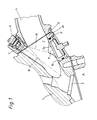
- the suction device according to FIG. 2 differs from that according to FIG. 1 in principle only in that the heating plate 9 protrudes into the suction channel 2 in the embodiment according to FIG. 2.
- the essentially flat, unsupported surface 9a of the heating plate 9, which the fuel jet coming from the injection nozzle 6 strikes, runs essentially parallel to the longitudinal axis of the intake duct 2.
- the angle of the surface 9a of the heating plate 9 with respect to the longitudinal axis of the suction duct or the axis of the fuel jet can be varied. However, it is important that the fuel jet strikes the surface 9a at an approximately acute angle.
- only a fuel jet can be sprayed out of the injection nozzle 6, which passes over and past the heating plate 9 and mixed with the combustion air into the valve opening 3 of the engine.
- the heating plate 9 in the embodiment according to FIG. 2 is supported on a cylindrical base part 15 via a support 14, which is narrow transversely to the flow direction of the combustion air.
- Plug contacts 16 for a PTC heating element in the heating plate 9 are also attached to the base part 15.
- the base part 15 is simply inserted into a cylindrical opening 17 in a channel wall 2a and is sealed in terms of heat and gas within the cylinder head by a sealing ring 18.
- the opening 17 is arranged on an underside of the channel wall 2a.
- An end face 19 of the base part 15 is flush with the suction channel wall surface of the suction channel 2.
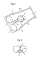
- the suction channel 2 divides in front of the valve opening 3 into two separate individual suction channels 20, 21.
- the heating plate 9 is arranged directly upstream of a partition 22 between the individual suction channels 20, 21. In this way, the support 14 of the heating plate 9 serves practically as an extension of the partition 22.
- a rib 23 can be mounted perpendicular to the surface of the plate in the extension of the partition 22.
- the surface 9a of the heating plate 9 can be provided with variously shaped ribs or spikes made of a good heat-conducting material.
- the heating plate 9 in the embodiment according to FIG. 2 lies extremely aerodynamically completely in the fanned-out fuel jet together with the intake air that mixes with the fuel in the intake duct 2.
- the base parts 15 can be fixed via two base parts 15 which hold the base parts and which are fastened to the cylinder head. These holders are not shown in the drawing. However, they engage fixing pins 24 of the base parts 15 and in particular ensure that the base parts 15 are dimensionally fixed in rotation.
Landscapes
- Engineering & Computer Science (AREA)
- Chemical & Material Sciences (AREA)
- Combustion & Propulsion (AREA)
- Mechanical Engineering (AREA)
- General Engineering & Computer Science (AREA)
- Fuel-Injection Apparatus (AREA)
- Cylinder Crankcases Of Internal Combustion Engines (AREA)
- Combustion Methods Of Internal-Combustion Engines (AREA)
Abstract
Description
Die Erfindung betrifft eine Ansaugeinrichtung für eine gemischverdichtende Brennkraftmaschine nach dem Oberbegriff des Patentanspruchs 1.The invention relates to an intake device for a mixture-compressing internal combustion engine according to the preamble of patent claim 1.
Eine solche Ansaugeinrichtung ist aus der DE-C 34 26 469 bekannt. Hierbei ist nahe der Motorventilöffnung ein ringförmiges Heizelement vorgesehen, in das der Kraftstoff schräg eingespritzt wird, wobei der Heizring mit seiner Längsachse im wesentlichen in Strömungsrichtung liegt. Nachteilig bei einem solchen Heizring ist es, daß der Kraftstoffstrahl durch eine der offenen Stirnseiten des Heizringes in diesen schräg eingeleitet werden muß. Da sich der Kraftstoffstrahl beim Austritt aus der Einspritzdüse auffächert, muß der Heizring entweder relativ nahe an der Einspritzdüse angeordnet sein, oder der sich auffächernde Kraftstoffstrahl trifft zum großen Teil auf die geschlossene Stirnringfläche des Heizringes sowie auf dessen Außenmantel auf. Dadurch kommt es zu einer unerwünschten Verwirbelung des eingespritzten Kraftstoffstrahles an dem Heizringelement. Letzterer Fall tritt insbesondere dann auf, wenn der Heizring in an sich erwünschter Weise möglichst nahe an der Motorventilöffnung angebracht ist und die Einspritzdüse nur mit einiger Entfernung zu dem Heizring vorgesehen werden kann. Solche Abstände sind häufig durch die Einbauverhältnisse zwangsläufig gegeben.Such a suction device is known from DE-C 34 26 469. Here, an annular heating element is provided near the engine valve opening, into which the fuel is injected at an angle, the heating ring having its longitudinal axis lying essentially in the direction of flow. The disadvantage of such a heating ring is that the fuel jet has to be introduced obliquely through one of the open end faces of the heating ring. Since the fuel jet fuses when it exits the injection nozzle, the heating ring must either be arranged relatively close to the injection nozzle, or the fanning fuel jet strikes a large part on the closed end ring surface of the heating ring and on its outer jacket. This leads to an undesirable swirling of the injected fuel jet on the heating ring element. The latter case occurs in particular when the heating ring is attached as close as possible to the engine valve opening in a desired manner and the injection nozzle can only be provided at some distance from the heating ring. Such distances are often inevitable due to the installation conditions.
Desweiteren ist aus der EP-A 0 343 652 eine Ansaugeinrichtung bekannt, die in ihrem Aufbau weitgehend mit derjenigen der gattungsbildenden Ansaugeinrichtung übereinstimmt und auch deren Nachteile besitzt.Furthermore, a suction device is known from EP-A 0 343 652, the structure of which largely corresponds to that of the generic suction device and also has its disadvantages.
Hier eine Verbesserung zu schaffen, ist die Aufgabe der vorliegenden Erfindung.To create an improvement here is the object of the present invention.
Gelöst wird diese Aufgabe durch die kennzeichnenden Merkmale des Anspruches 1.This object is achieved by the characterizing features of claim 1.
Bei der erfindungsgemäßen Ausführung wird die Heizplatte von dem auf die Motorventilöffnung ausgerichteten Kraftstoffstrahl schräg beaufschlagt. Dadurch bildet das erfindungsgemäße Heizelement nur einen äußerst geringen Strömungswiderstand, wodurch übermäßige unkontrollierte Verwirbelungen im Bereich des Heizelementes vermieden werden.In the embodiment according to the invention, the heating plate is acted on obliquely by the fuel jet directed at the engine valve opening. As a result, the heating element according to the invention forms only an extremely low flow resistance, as a result of which excessive uncontrolled eddies in the area of the heating element are avoided.
Bei der Ausführung nach Fig. 1, bei der die Heizplatte in die Wand der Ansaugleitung integriert ist, ist der durch ein solches Heizelement bewirkte Strömungswiderstand naturgemäß am geringsten. Da der Kraftstoffstrahl jedoch auf seinem Weg in die Ventilöffnung möglichst geringen Kontakt zu den Wänden der Ansaugleitung haben soll, kann ein in die Ansaugleitungswand integriertes Heizelement nicht in der Hauptströmungsachse des Kraftstoffstrahles angeordnet sein. Notwendig ist es hier vielmehr, den Kraftstoffstrahl in einen Haupt-und Nebenstrahl aufzuteilen, wobei der Nebenstrahl bezüglich seines Mengenstromes wesentlich kleiner als der Hauptstrahl ist. Erzeugt wird der Nebenstrahl durch eine Zusatzöffnung in der Einspritzdüse. Der Nebenstrahl wird dabei so ausgerichtet, daß er auf das in der Leitungswand flächenschlüssig liegende Heizelement direkt auftrifft und von dort in den Hauptstrom rückreflektiert wird.In the embodiment according to FIG. 1, in which the heating plate is integrated in the wall of the suction line, the flow resistance caused by such a heating element is naturally the lowest. However, since the fuel jet should have as little contact as possible with the walls of the intake line on its way into the valve opening, a heating element integrated in the intake line wall cannot be arranged in the main flow axis of the fuel jet. Rather, it is necessary here to divide the fuel jet into a main jet and a secondary jet, the secondary jet being considerably smaller than the main jet with respect to its mass flow. The secondary jet is generated through an additional opening in the injection nozzle. The secondary jet is aligned so that it strikes the heating element lying flush in the conduit wall and is reflected back into the main stream from there.
Die erfindungsgemäße Ausführung erzeugt durch die freie Anordnung innerhalb des Einlaßkanals zwar einen etwas größeren Widerstand. Vorteilhaft bei dieser Ausführung ist jedoch, daß durch ein nahezu allseitiges Umströmen der Heizelement-Platte eine gute Kraftstofferwärmung mit einer gleichzeitigen guten Luftvorwärmung erfolgen kann. Desweiteren kann die frei in den Ansaugkanal ragende Heizplatte derart in einem spitzen Winkel in den Einspritzstrahl ausgerichtet werden, daß eine Aufteilung des Einspritzstrahles in einen Haupt- und einen kleineren Nebenstrahl nicht notwendig ist.The embodiment according to the invention produces a somewhat greater resistance due to the free arrangement within the inlet channel. An advantage of this design, however, is that good fuel heating with good air preheating can be achieved by flowing around the heating element plate almost from all sides. Furthermore, the heating plate projecting freely into the intake duct can be aligned at an acute angle in the injection jet in such a way that it is not necessary to split the injection jet into a main jet and a smaller secondary jet.
Zweckmäßige Ausgestaltungen der erfindungsgemäßen Lösung sind Gegenstand der Unteransprüche und werden im Zusammenhang mit der Beschreibung von in der Zeichnung dargestellten Ausführungsbeispielen der Erfindung noch näher erläutert werden.Appropriate embodiments of the solution according to the invention are the subject of the subclaims and will be explained in more detail in connection with the description of exemplary embodiments of the invention illustrated in the drawing.
In der Zeichnung zeigen
- Fig. 1 einen Schnitt durch den Ansaugkanal eines Zylinderkopfes mit in die Ansaugkanalwand flächenschlüssig integriertem Heizelement,
- Fig. 2 einen Schnitt durch den Ansaugkanal eines Zylinderkopfes mit in den Ansaugkanal hineinragender Heizplatte,
- Fig. 3 einen Schnitt durch den Ansaugkanal nach Linie 111-111 in Fig. 2,
- Fig. 4 einen Schnitt durch einen Teilbereich des Ansaugkanales nach Linie IV-IV in Fig. 2.
- 1 shows a section through the intake duct of a cylinder head with a heating element integrated flush in the intake duct wall,
- 2 shows a section through the intake duct of a cylinder head with the heating plate protruding into the intake duct,
- 3 shows a section through the intake duct along line 111-111 in FIG. 2,
- 4 shows a section through a partial area of the intake duct according to line IV-IV in FIG. 2.
Die in Fig. 1 dargestellt Saugeinrichtung umfaßt einen in einem Zylinderkopf 1 einer nicht näher dargestellten Brennkraftmaschine vorgesehenen Saugkanal 2, der über Ventilöffnungen 3 in einen der Motorzylinder 4 mündet, und eine sich an den Saugkanal 2 anschließende Saugrohrleitung 5. In der Saugrohrleitung 5 ist eine Einspritzdüse 6 in Strömungsrichtung der Verbrennungsluft geneigt angeordnet, deren Düsenspitze 7 etwa im Bereich der Flanschebene 8 zwischen Zylinderkopf 1 und Saugrohrleitung 5 in den Saugrohrkanal 2 einmündet. Mit der Einspritzdüse 6 wird Kraftstoff dosiert in die Verbrennungsluft eingespritzt. Um bei einem Kaltstart und in der Warmlaufphase der Brennkraftmaschine im Saugrohr eine gute Gemischzusammensetzung von Kraftstoff und Verbrennungsluft zu erreichen, ist in dem Saugkanal 2 eine Heizplatte 9 flächenschlüssig in die Kanalinnenwand eingesetzt. Es handelt sich dabei um eine Heizplatte 9 mit einem PTC-Element, das in eine Öffnung 10 der Kanalwand 2a eingeschoben ist. Aus Gründen einer einfachen Herstellung ist die Öffnung 10 rund und die Heizplatte 9 zylindrisch ausgebildet. Die Zentrierung und Dichtung der Heizplatte in der Öffnung erfolgt über eine insbesondere wärmeisolierende Radialdichtung 11. Das PTC-Element ist elektrisch kurzfristig auf Temperaturen bis zu 180 Grad Celsius aufheizbar.The suction device shown in Fig. 1 comprises a provided in a cylinder head 1 of an internal combustion engine, not shown, the
Durch die Einspritzdüse 6 wird Kraftstoff in einem Haupt- und einem Nebenstrahl 12 bzw. 13 in den Saugkanal in Richtung der Ventilöffnungen 3 eingespritzt. Über den Nebenstrahl 13 wird etwa ein Drittel des Kraftstoffes eingebracht, während der Hauptanteil von dem Hauptstrahl 12 eingeführt wird. Der über den Nebenstrahl 13 eingeführte Kraftstoffstrahl ist direkt unter einem Winkel von etwa 45 Winkelgrad auf die Heizplatte 9 gerichtet, an der sich dieser Kraftstoffanteil bei eingeschalteter Heizplatte erwärmen kann. Eine Erwärmung eines solchen Anteiles reicht zur Vermeidung einer Kraftstoffkondensatbildung bereits aus, wenn durch eine entsprechend gewählte Größe der Heizplatte und der aufgebrachten Heizleistung der auftreffende Kraftstoffteilstrom tatsächlich weitgehendst verdampft werden kann. Der Vorteil dieser Ausführung besteht darin, daß bei einem vernachlässigbar geringen Strömungswiderstand eine relativ große Heizfläche eingesetzt werden kann. Ferner ist es möglich, die Heizfläche sehr nahe an der Ventilöffnung anzuordnen. Auch konstruktiv handelt es sich um eine einfach herstellbare Anordnung, da die Heizplatte zylindrisch rund in eine entsprechend gebohrte Öffnung einbringbar ist.Fuel is injected through the
Die Ansaugeinrichtung nach der Fig. 2 unterscheidet sich von derjenigen nach der Fig. 1 im Prinzip lediglich dadurch, daß die Heizplatte 9 bei der Ausführung nach Fig. 2 in den Saugkanal 2 hineinragt. Die im wesentlichen flache ungestützte Oberfläche 9a der Heizplatte 9, auf die der aus der Einspritzdüse 6 kommende Kraftstoffstrahl auftrifft, verläuft im wesentlichen parallel zu der Längsachse des Ansaugkanales 2. Die Oberfläche 9a der Heizplatte 9 kann in ihrem Winkel gegenüber der Längsachse des Saugkanales bzw. der Achse des Brennstoffstrahles variiert werden. Wichtig ist jedoch, daß ein Auftreffen des Brennstoffstrahles auf die Oberfläche 9a unter einem etwa spitzen Winkel gegeben ist. Im Gegensatz zu der Ausführung nach Fig. 1 kann aus der Einspritzdüse 6 lediglich ein Brennstoffstrahl ausgespritzt werden, der über und an der Heizplatte 9 vorbei mit der Verbrennungsluft vermischt in die Ventilöffnung 3 des Motors gelangt.The suction device according to FIG. 2 differs from that according to FIG. 1 in principle only in that the
Die Heizplatte 9 in der Ausführung nach Fig. 2 ist über eine quer zur Strömungsrichtung der Verbrennungsluft schmale Stütze 14 an einem zylindrischen Sockelteil 15 abgestützt. Am Sockelteil 15 sind ferner Steckkontakte 16 für ein PTC-Heizelement in der Heizplatte 9 angebracht. Das Sockelteil 15 ist einfach in eine zylindrische Öffnung 17 in einer Kanalwand 2a eingeschoben und durch einen Dichtring 18 wärme- und gasmäßig innerhalb des Zylinderkopfes gedichtet. Die Öffnung 17 ist dabei an einer Unterseite der Kanalwand 2a angeordnet. Dabei liegt eine Stirnseite 19 des Sockelteils 15 bündig zur Saugkanal-Wandfläche des Saugkanals 2.The
Bei einem Vier-Ventilmotor teilt sich der Saugkanal 2 vor der Ventilöffnung 3 in zwei getrennte Einzelsaugkanäle 20, 21 auf. Bei einer solchen Ausführung ist die Heizplatte 9 direkt stromauf einer Trennwand 22 zwischen den Einzelsaugkanälen 20, 21 angeordnet. Auf diese Weise dient die Stütze 14 der Heizplatte 9 praktisch als Verlängerung der Trennwand 22.In the case of a four-valve engine, the
Auf der Oberfläche 9a der Heizplatte 9 kann in Verlängerung der Trennwand 22 eine Rippe 23 senkrecht zur Plattenoberfläche angebracht sein. Um einen weiterhin verbesserten Wärmeübergang von dem Heizelement der Heizplatte 9 auf das Kraftstoff-Verbrennungsluft-Gemisch zu erzielen, kann die Oberfläche 9a der Heizplatte 9 mit verschiedenartig geformten Rippen oder Stacheln aus gut wärmeleitendem Material versehen sein. Die Heizplatte 9 bei der Ausführung nach Fig. 2 liegt äußerst strömungsgünstig vollständig in dem aufgefächerten Kraftstoffstrahl zusammen mit der sich in dem Ansaugkanal 2 mit dem Kraftstoff vermischenden Ansaugluft.On the
Die Fixierung der Sockelteile 15 kann über je zwei Sockelteile 15 erfassende Halter erfolgen, die an dem Zylinderkopf befestigt werden. Diese Halter sind in der Zeichnung nicht dargestellt. Sie greifen jedoch an Fixierstiften 24 der Sockelteile 15 an und sorgen insbesondere für eine maßgerechte Drehfixierung der Sockelteile 15.The
Claims (9)
daß der Heizkörper als flache Heizplatte (9) ausgebildet ist, die über eine quer zur Strömungsrichtung der Verbrennungsluft schmal ausgebildete Stütze (13) am Sockelteil (15) gehalten ist und deren vom Kraftstoff beaufschlagte Oberfläche (9a) parallel oder in einem Winkel zur Längsachse des Saugkanals (2) verläuft.1.Intake device for a mixture-compressing internal combustion engine with a heating device used in the suction duct downstream of an injection nozzle, which consists of a flat heating element which is essentially flowed around by the combustion air and a base part via which the heating element is kept essentially thermally insulated on the cylinder head, the injection nozzle facing surface of the radiator is acted upon by at least part of the amount of fuel emitted by the injection nozzle and a connection for the radiator to a power source is provided on the base part, characterized in that
that the radiator is designed as a flat heating plate (9) which has a transverse to the stream Direction of combustion air narrow support (13) is held on the base part (15) and the surface acted upon by the fuel (9a) runs parallel or at an angle to the longitudinal axis of the suction channel (2).
daß im Verlauf der einen Saugkanal (2) begrenzenden Kanalwand (2a) eine Öffnung (10, 17) vorgesehen ist, durch welche der Heizkörper in den Saugkanal (2) einführbar ist und innerhalb der die Heizplatte (9) über das Sokkelteil (15) am Zylinderkopf (1) fixiert ist.2. Suction device according to claim 1, characterized in
that an opening (10, 17) is provided in the course of the channel wall (2a) delimiting a suction channel (2), through which the heating element can be inserted into the suction channel (2) and within which the heating plate (9) via the base part (15) is fixed to the cylinder head (1).
daß das Sockelteil (15) durch einen am Umfang angeordneten Dichtring (18) in der Öffnung (17) dichtend eingesetzt ist.3. Suction device according to claim 1 or 2, characterized in
that the base part (15) is inserted sealingly in the opening (17) by a sealing ring (18) arranged on the circumference.
dadurch gekennzeichnet,
daß das Sockelteil (15) mit einer weitgehend bündig zur Saugkanal-Wandfläche verlaufenden Stirnseite (21) ausgebildet ist.4. Suction device according to one of claims 1 to 3,
characterized,
that the base part (15) is formed with a largely flush to the suction channel wall surface end (21).
dadurch gekennzeichnet,
daß bei einem am stromabseitigen Ende durch eine Trennwand (22) in zwei Einzelsaugkanäle (20, 21) aufgeteilten Saugkanal (2) in Verlängerung der Trennwand (22) eine beide Einzelsaugkanäle (20, 21) tangierende Heizplatte (9) vorgesehen ist.5. Suction device according to one of claims 1 to 4,
characterized,
that in a suction channel (2) divided at the downstream end by a partition (22) into two individual suction channels (20, 21) in extension of the partition (22), a heating plate (9) tangent to both individual suction channels (20, 21) is provided.
dadurch gekennzeichnet,
daß die Stütze (13) eine Verlängerung der Trennwand (22) bildet.6. Suction device according to one of claims 1 to 5,
characterized,
that the support (13) forms an extension of the partition (22).
dadurch gekennzeichnet,
daß die Heizplatte (9) unmittelbar stromauf der Trennwand (22) angeordnet ist.7. Suction device according to one of claims 1 to 6,
characterized,
that the heating plate (9) is arranged immediately upstream of the partition (22).
dadurch gekennzeichnet,
daß von der mit Kraftstoff beaufschlagten Oberfläche (9a) der Heizplatte (9) aus mindestens eine in Strömungsrichtung verlaufende Rippe (23) absteht.8. Suction device according to one of claims 1 to 7,
characterized,
that at least one rib (23) extending in the flow direction protrudes from the fuel-charged surface (9a) of the heating plate (9).
dadurch gekennzeichnet,
daß die Heizplatte (9) wärmeisoliert flächenschlüssig in die Wand des Saugkanals (2) eingesetzt ist.9. Suction device according to one of claims 1 to 8,
characterized,
that the heating plate (9) is insulated in a surface-fitting manner in the wall of the suction channel (2).
Applications Claiming Priority (2)
| Application Number | Priority Date | Filing Date | Title |
|---|---|---|---|
| DE4024005 | 1990-07-28 | ||
| DE4024005A DE4024005C2 (en) | 1990-07-28 | 1990-07-28 | Intake device for a mixture-compressing internal combustion engine |
Publications (2)
| Publication Number | Publication Date |
|---|---|
| EP0469261A1 true EP0469261A1 (en) | 1992-02-05 |
| EP0469261B1 EP0469261B1 (en) | 1994-07-27 |
Family
ID=6411198
Family Applications (1)
| Application Number | Title | Priority Date | Filing Date |
|---|---|---|---|
| EP91108499A Expired - Lifetime EP0469261B1 (en) | 1990-07-28 | 1991-05-25 | Suction device for a mixture compressing internal combustion engine |
Country Status (4)
| Country | Link |
|---|---|
| US (1) | US5154154A (en) |
| EP (1) | EP0469261B1 (en) |
| JP (1) | JPH0814267B2 (en) |
| DE (1) | DE4024005C2 (en) |
Cited By (3)
| Publication number | Priority date | Publication date | Assignee | Title |
|---|---|---|---|---|
| DE4314283A1 (en) * | 1993-04-30 | 1994-11-10 | Freudenberg Carl Fa | Heating module for an internal combustion engine |
| US5642695A (en) * | 1995-03-30 | 1997-07-01 | Firma Carl Freudenberg | Heating module for a combustion engine |
| EP1251265A3 (en) * | 2001-04-21 | 2003-07-09 | Filterwerk Mann + Hummel Gmbh | Intake device for an internal combustion engine having an element for evaporating injected fuel |
Families Citing this family (6)
| Publication number | Priority date | Publication date | Assignee | Title |
|---|---|---|---|---|
| JPH05180124A (en) * | 1992-01-07 | 1993-07-20 | Mitsubishi Electric Corp | Fuel supply device of gasoline internal combustion engine |
| WO1996032582A1 (en) * | 1995-04-12 | 1996-10-17 | Allen Caggiano | Fluid vaporization system |
| DE19522074A1 (en) * | 1995-06-17 | 1996-12-19 | Bosch Gmbh Robert | Fuel supply device for an internal combustion engine |
| DE19638323A1 (en) * | 1996-09-19 | 1998-04-02 | Daimler Benz Ag | Method for operating an internal combustion engine and internal combustion engine |
| US6298834B1 (en) * | 1998-04-22 | 2001-10-09 | Safe Energy Systems, Inc. | Fuel vaporizing attachment for liquid fueled internal combustion engines |
| JP4657177B2 (en) * | 2006-08-29 | 2011-03-23 | 本田技研工業株式会社 | Internal combustion engine |
Citations (4)
| Publication number | Priority date | Publication date | Assignee | Title |
|---|---|---|---|---|
| US4313413A (en) * | 1979-09-07 | 1982-02-02 | Toyota Jidosha Kogyo Kabushiki Kaisha | Fuel vaporization promoting device for an internal combustion engine |
| DE3426469C2 (en) * | 1984-07-18 | 1986-05-28 | Daimler-Benz Ag, 7000 Stuttgart | Intake system for a mixture-compressing internal combustion engine |
| EP0234052A1 (en) * | 1986-02-20 | 1987-09-02 | Texas Instruments Holland B.V. | Liquid heating device |
| EP0343652A1 (en) * | 1988-05-24 | 1989-11-29 | Texas Instruments Holland B.V. | Internal combustion engine of the injection type, and plate intended for fitting between the inlet ports of a cylinder block of such an engine and an inlet tube |
Family Cites Families (12)
| Publication number | Priority date | Publication date | Assignee | Title |
|---|---|---|---|---|
| US1417308A (en) * | 1921-04-14 | 1922-05-23 | John T Ellis | Explosive-engine attachent |
| US1561815A (en) * | 1924-01-10 | 1925-11-17 | Leonard E Aske | Electric heater or vaporizer |
| US3930477A (en) * | 1971-08-12 | 1976-01-06 | Jordan Wilmer C | Electric heating means for fuel vaporization in internal combustion engines |
| JPS4874993A (en) * | 1971-12-31 | 1973-10-09 | ||
| JPS5457016A (en) * | 1977-10-14 | 1979-05-08 | Nissan Motor Co Ltd | Fuel supply system for internal combustion engine |
| JPS6010532B2 (en) * | 1978-07-07 | 1985-03-18 | 東洋インキ製造株式会社 | Aqueous resin dispersion composition |
| JPS5925113B2 (en) * | 1978-12-27 | 1984-06-14 | 株式会社日本自動車部品総合研究所 | engine intake system |
| US4458654A (en) * | 1982-03-12 | 1984-07-10 | Walbro Corporation | Fuel vapor injection system |
| NL8601460A (en) * | 1986-06-05 | 1988-01-04 | Texas Instruments Holland | INTAKE MANIFOLD OF A COMBUSTION ENGINE AND HEATING DEVICE REFERRED TO FOR THAT MANIFOLD. |
| NL8602782A (en) * | 1986-11-03 | 1988-06-01 | Texas Instruments Holland | COMBUSTION ENGINE. |
| DE3921739C1 (en) * | 1989-07-01 | 1990-11-08 | Daimler-Benz Aktiengesellschaft, 7000 Stuttgart, De | |
| NL9000910A (en) * | 1990-04-17 | 1991-11-18 | Texas Instruments Holland | INJECTION COMBUSTION ENGINE WITH ELECTRICAL SPARK IGNITION. |
-
1990
- 1990-07-28 DE DE4024005A patent/DE4024005C2/en not_active Expired - Fee Related
-
1991
- 1991-05-25 EP EP91108499A patent/EP0469261B1/en not_active Expired - Lifetime
- 1991-07-04 JP JP3189489A patent/JPH0814267B2/en not_active Expired - Fee Related
- 1991-07-10 US US07/727,951 patent/US5154154A/en not_active Expired - Fee Related
Patent Citations (4)
| Publication number | Priority date | Publication date | Assignee | Title |
|---|---|---|---|---|
| US4313413A (en) * | 1979-09-07 | 1982-02-02 | Toyota Jidosha Kogyo Kabushiki Kaisha | Fuel vaporization promoting device for an internal combustion engine |
| DE3426469C2 (en) * | 1984-07-18 | 1986-05-28 | Daimler-Benz Ag, 7000 Stuttgart | Intake system for a mixture-compressing internal combustion engine |
| EP0234052A1 (en) * | 1986-02-20 | 1987-09-02 | Texas Instruments Holland B.V. | Liquid heating device |
| EP0343652A1 (en) * | 1988-05-24 | 1989-11-29 | Texas Instruments Holland B.V. | Internal combustion engine of the injection type, and plate intended for fitting between the inlet ports of a cylinder block of such an engine and an inlet tube |
Cited By (4)
| Publication number | Priority date | Publication date | Assignee | Title |
|---|---|---|---|---|
| DE4314283A1 (en) * | 1993-04-30 | 1994-11-10 | Freudenberg Carl Fa | Heating module for an internal combustion engine |
| US5438969A (en) * | 1993-04-30 | 1995-08-08 | Firma Carl Freudenberg | Heating module for an internal combustion engine |
| US5642695A (en) * | 1995-03-30 | 1997-07-01 | Firma Carl Freudenberg | Heating module for a combustion engine |
| EP1251265A3 (en) * | 2001-04-21 | 2003-07-09 | Filterwerk Mann + Hummel Gmbh | Intake device for an internal combustion engine having an element for evaporating injected fuel |
Also Published As
| Publication number | Publication date |
|---|---|
| DE4024005A1 (en) | 1992-02-06 |
| JPH0814267B2 (en) | 1996-02-14 |
| DE4024005C2 (en) | 1995-04-13 |
| US5154154A (en) | 1992-10-13 |
| EP0469261B1 (en) | 1994-07-27 |
| JPH04232368A (en) | 1992-08-20 |
Similar Documents
| Publication | Publication Date | Title |
|---|---|---|
| DE10115282B4 (en) | Inlet air control device and internal combustion engine in which it is mounted | |
| DE4212251C1 (en) | ||
| EP1196687A1 (en) | Fluid feed duct for a hot fluid in a hollow structure | |
| DE3426469A1 (en) | Intake system for a mixture-compressing internal combustion engine | |
| DE3020924A1 (en) | DIESEL ENGINE WITH CHAMBER SYSTEM | |
| DE3819898C2 (en) | ||
| EP0469261A1 (en) | Suction device for a mixture compressing internal combustion engine | |
| EP0258207A2 (en) | Intake conduit for internal-combustion engines | |
| DE69636033T2 (en) | DEVICE FOR AIR SUPPORTED FUEL INJECTION | |
| DE4420247B4 (en) | Exhaust gas recirculation device for internal combustion engines, in particular with plastic suction pipes | |
| DE2949096C2 (en) | Mixture formers for internal combustion engines | |
| EP0477923B1 (en) | Injection internal combustion engine with electrical spark ignition and heating unit | |
| DE2200818A1 (en) | Inlet and outlet lines for an internal combustion engine and their flow ducts | |
| EP0474623B1 (en) | Externally ignited two stroke internal combustion engine with crankcase scavening | |
| DE2508081A1 (en) | COMBUSTION MACHINE | |
| DE2616452B2 (en) | Combustion chamber | |
| DE3528804C2 (en) | ||
| DE4122124C2 (en) | ||
| DE2416975A1 (en) | CARBURETOR FOR A COMBUSTION ENGINE | |
| DE2805091A1 (en) | Throttle for external ignition IC engine - has profiled section to produce supersonic velocities at low loads to improve combustion | |
| EP0400212A1 (en) | Air-fuel mixture preparing device for internal combustion engine | |
| CH673683A5 (en) | ||
| DE102020112870B4 (en) | Compressor device of a charging device for an internal combustion engine | |
| DE3339680C1 (en) | Mixture-forming device for internal combustion engines | |
| DE3509256A1 (en) | Internal combustion engine |
Legal Events
| Date | Code | Title | Description |
|---|---|---|---|
| PUAI | Public reference made under article 153(3) epc to a published international application that has entered the european phase |
Free format text: ORIGINAL CODE: 0009012 |
|
| 17P | Request for examination filed |
Effective date: 19911116 |
|
| AK | Designated contracting states |
Kind code of ref document: A1 Designated state(s): FR GB IT SE |
|
| 17Q | First examination report despatched |
Effective date: 19920602 |
|
| ITF | It: translation for a ep patent filed |
Owner name: BARZANO' E ZANARDO ROMA S.P.A. |
|
| GRAA | (expected) grant |
Free format text: ORIGINAL CODE: 0009210 |
|
| AK | Designated contracting states |
Kind code of ref document: B1 Designated state(s): FR GB IT SE |
|
| ET | Fr: translation filed | ||
| GBT | Gb: translation of ep patent filed (gb section 77(6)(a)/1977) |
Effective date: 19940901 |
|
| EAL | Se: european patent in force in sweden |
Ref document number: 91108499.4 |
|
| PLBE | No opposition filed within time limit |
Free format text: ORIGINAL CODE: 0009261 |
|
| STAA | Information on the status of an ep patent application or granted ep patent |
Free format text: STATUS: NO OPPOSITION FILED WITHIN TIME LIMIT |
|
| 26N | No opposition filed | ||
| REG | Reference to a national code |
Ref country code: GB Ref legal event code: 732E |
|
| REG | Reference to a national code |
Ref country code: FR Ref legal event code: TP |
|
| REG | Reference to a national code |
Ref country code: GB Ref legal event code: 732E |
|
| PGFP | Annual fee paid to national office [announced via postgrant information from national office to epo] |
Ref country code: GB Payment date: 20000511 Year of fee payment: 10 |
|
| PGFP | Annual fee paid to national office [announced via postgrant information from national office to epo] |
Ref country code: FR Payment date: 20000518 Year of fee payment: 10 |
|
| PGFP | Annual fee paid to national office [announced via postgrant information from national office to epo] |
Ref country code: SE Payment date: 20000523 Year of fee payment: 10 |
|
| PG25 | Lapsed in a contracting state [announced via postgrant information from national office to epo] |
Ref country code: GB Free format text: LAPSE BECAUSE OF NON-PAYMENT OF DUE FEES Effective date: 20010525 |
|
| PG25 | Lapsed in a contracting state [announced via postgrant information from national office to epo] |
Ref country code: SE Free format text: LAPSE BECAUSE OF NON-PAYMENT OF DUE FEES Effective date: 20010526 |
|
| GBPC | Gb: european patent ceased through non-payment of renewal fee |
Effective date: 20010525 |
|
| PG25 | Lapsed in a contracting state [announced via postgrant information from national office to epo] |
Ref country code: FR Free format text: LAPSE BECAUSE OF NON-PAYMENT OF DUE FEES Effective date: 20020131 |
|
| PG25 | Lapsed in a contracting state [announced via postgrant information from national office to epo] |
Ref country code: IT Free format text: LAPSE BECAUSE OF NON-PAYMENT OF DUE FEES;WARNING: LAPSES OF ITALIAN PATENTS WITH EFFECTIVE DATE BEFORE 2007 MAY HAVE OCCURRED AT ANY TIME BEFORE 2007. THE CORRECT EFFECTIVE DATE MAY BE DIFFERENT FROM THE ONE RECORDED. Effective date: 20050525 |