EP0343652A1 - Internal combustion engine of the injection type, and plate intended for fitting between the inlet ports of a cylinder block of such an engine and an inlet tube - Google Patents
Internal combustion engine of the injection type, and plate intended for fitting between the inlet ports of a cylinder block of such an engine and an inlet tube Download PDFInfo
- Publication number
- EP0343652A1 EP0343652A1 EP89109419A EP89109419A EP0343652A1 EP 0343652 A1 EP0343652 A1 EP 0343652A1 EP 89109419 A EP89109419 A EP 89109419A EP 89109419 A EP89109419 A EP 89109419A EP 0343652 A1 EP0343652 A1 EP 0343652A1
- Authority
- EP
- European Patent Office
- Prior art keywords
- plate
- combustion engine
- inlet
- chamber
- electrical resistance
- Prior art date
- Legal status (The legal status is an assumption and is not a legal conclusion. Google has not performed a legal analysis and makes no representation as to the accuracy of the status listed.)
- Granted
Links
- 238000002485 combustion reaction Methods 0.000 title claims abstract description 17
- 238000002347 injection Methods 0.000 title claims abstract description 7
- 239000007924 injection Substances 0.000 title claims abstract description 7
- 238000010438 heat treatment Methods 0.000 claims abstract description 27
- 239000000446 fuel Substances 0.000 claims abstract description 17
- 239000000463 material Substances 0.000 claims abstract description 12
- 239000004020 conductor Substances 0.000 claims description 9
- 229910000838 Al alloy Inorganic materials 0.000 description 4
- 238000009413 insulation Methods 0.000 description 4
- 239000000203 mixture Substances 0.000 description 3
- 230000003197 catalytic effect Effects 0.000 description 2
- 238000006243 chemical reaction Methods 0.000 description 2
- 238000013461 design Methods 0.000 description 2
- 239000003822 epoxy resin Substances 0.000 description 2
- 239000011810 insulating material Substances 0.000 description 2
- 229920000647 polyepoxide Polymers 0.000 description 2
- 238000012360 testing method Methods 0.000 description 2
- 230000032683 aging Effects 0.000 description 1
- 238000000889 atomisation Methods 0.000 description 1
- 238000009835 boiling Methods 0.000 description 1
- 230000005611 electricity Effects 0.000 description 1
- 229930195733 hydrocarbon Natural products 0.000 description 1
- 150000002430 hydrocarbons Chemical class 0.000 description 1
- 238000012986 modification Methods 0.000 description 1
- 230000004048 modification Effects 0.000 description 1
- 238000012856 packing Methods 0.000 description 1
- 239000004033 plastic Substances 0.000 description 1
- 239000000843 powder Substances 0.000 description 1
- 238000007789 sealing Methods 0.000 description 1
- 238000012546 transfer Methods 0.000 description 1
- 238000009834 vaporization Methods 0.000 description 1
- 230000008016 vaporization Effects 0.000 description 1
- 238000003466 welding Methods 0.000 description 1
Images

Classifications
-
- F—MECHANICAL ENGINEERING; LIGHTING; HEATING; WEAPONS; BLASTING
- F02—COMBUSTION ENGINES; HOT-GAS OR COMBUSTION-PRODUCT ENGINE PLANTS
- F02M—SUPPLYING COMBUSTION ENGINES IN GENERAL WITH COMBUSTIBLE MIXTURES OR CONSTITUENTS THEREOF
- F02M31/00—Apparatus for thermally treating combustion-air, fuel, or fuel-air mixture
- F02M31/02—Apparatus for thermally treating combustion-air, fuel, or fuel-air mixture for heating
- F02M31/12—Apparatus for thermally treating combustion-air, fuel, or fuel-air mixture for heating electrically
- F02M31/135—Fuel-air mixture
-
- F—MECHANICAL ENGINEERING; LIGHTING; HEATING; WEAPONS; BLASTING
- F02—COMBUSTION ENGINES; HOT-GAS OR COMBUSTION-PRODUCT ENGINE PLANTS
- F02B—INTERNAL-COMBUSTION PISTON ENGINES; COMBUSTION ENGINES IN GENERAL
- F02B2275/00—Other engines, components or details, not provided for in other groups of this subclass
- F02B2275/14—Direct injection into combustion chamber
-
- Y—GENERAL TAGGING OF NEW TECHNOLOGICAL DEVELOPMENTS; GENERAL TAGGING OF CROSS-SECTIONAL TECHNOLOGIES SPANNING OVER SEVERAL SECTIONS OF THE IPC; TECHNICAL SUBJECTS COVERED BY FORMER USPC CROSS-REFERENCE ART COLLECTIONS [XRACs] AND DIGESTS
- Y02—TECHNOLOGIES OR APPLICATIONS FOR MITIGATION OR ADAPTATION AGAINST CLIMATE CHANGE
- Y02T—CLIMATE CHANGE MITIGATION TECHNOLOGIES RELATED TO TRANSPORTATION
- Y02T10/00—Road transport of goods or passengers
- Y02T10/10—Internal combustion engine [ICE] based vehicles
- Y02T10/12—Improving ICE efficiencies
Definitions
- the invention relates to an internal-combustion engine of the injection type, comprising at least one cylinder which is provided with an inlet channel with inlet valve, on which inlet channel an inlet tube with fuel injector is fixed, while a heating element projects into the inlet channel of said cylinder, said heating element having a heat sink, electrical resistance means disposed thereon, and current supply means.
- petrol consists of a mixture of hydrocarbons with a boiling range of about 30°C to about 200°C and with a cold engine the temperature level is not high enough to vaporize the fuel, an additional quantity of fuel must be fed in when the engine is cold, in order to obtain a combustible mixture. This leads to a high exhaust gas emission. At a low engine temperature both petrol consumption and the exhaust gas emission are therefore relatively high.
- the petrol is sprayed on the heating element heated in a short time to the desired temperature, and is thereby heated to the desired temperature.
- the petrol will consequently vaporize better, and a better mix with the combustion air is also achieved.
- the heating element is switched off when the engine is warm enough to take over the vaporization of the petrol.
- the heating element is designed in the form of a pipe enclosed by an insulation tube. Both the pipe and the tube are provided with a flange, and these flanges lie in a recess of the cylinder head and are fixed by the inlet tube.
- a problem with the above-mentioned insulation tube is that the heating element is thermally insulated relative to the engine block and that when the engine is hot and the heating element is thus switched off, the insulation tube receives no heat from the engine block.
- the fuel atomized on the insulation tube condenses on this tube. Particularly when the ambient temperature is low, this causes cold spot problems which result in reduced running performance of the engine.
- Another problem with the fixing of the pipe and the tube described above is that an additional recess has to be provided in the cylinder for said flanges.
- the object of the invention is to avoid these problems and produce an internal-combustion engine of the type indicated in the preamble, the heating element of which has a thermally conducting connection with the cylinder head, and for the fixing of which no additional provisions need be made in the cylinder head.
- the internal-combustion engine is to this end characterized in that the heating element is not fitted in a thermally insulated manner, and is integrated in a plate which is clamped between said inlet nozzle and the head of said cylinder, and electrical resistance means are provided in a chamber whose top face forms part of the heat sink.
- This chamber is of optimum design as regards the medium to be heated and is closed off at the rear side towards the inlet nozzle.
- Said plate is made from a good heat-conducting material, for example an aluminium alloy.
- the seal between this plate and the cylinder head is a good heat-conducting gasket, for example an aluminium alloy.
- the seal between the plate and the inlet tube is, on the other hand, made of an insulating material, for example paper.
- the injected fuel comes into good contact with the heating element because it is directed by the injector towards the heat sink, where the PTC tablet is fitted on the spot, and also because through atomization of the fuel contact takes place with a cylindrically curved wall which is connected by means of material bridges to the PTC chamber.
- the heat flow from and to the cylinder head can be influenced by altering the dimensions of these material bridges. All this is selected in such a way that the most heat, the highest temperature level and the best heat transfer are achieved on the face where the atomized fuel flow comes into contact with the heat sink.
- the desired fuel heating for the entire engine can be achieved with a single element.
- the external current supply to the heating elements is very simple if the PTC tablets of all heating elements are connected to a single connector pin by means of insulated current conductors embedded in the plate.
- the invention also relates to a plate intended for fitting between the inlet ports of a cylinder block of a direct injection engine and an inlet tube.
- This plate according to the invention has a number of projecting heating elements which are connected to the plate, each heating element having a chamber projecting relative to the plate surface and containing electrical resistance means, in particular one or more PTC tablets.
- the top part of an internal-combustion engine shown in Fig. has a cylinder head 1, on which an inlet tube 2 with fuel injector 3 is fixed.
- Inlet tube 2 opens out into an inlet channel 4 of the cylinder head.
- the inlet valve 5 is located in that channel.
- a plate 6 of heat-conducting material for example an aluminium alloy, is clamped between the inlet tube 2 and the cylinder head 1. In the case shown in the drawing this plate is common to four cylinders.
- recesses 7 are disposed in the plate and fixing holes 8 are also cut out in the plate.
- the plate At each inlet channel 4 the plate is provided with an aperture, and into each of said apertures projects a chamber 11, which is at right angles to the surface of the gasket, and a cylindrical surface 12 the width of which is at its maximum at the connection to the chamber 11 and at its minimum diagonally opposite.
- the cylindrical surface part of the lowest width is provided with a recess 13, through which the fuel injector projects.
- the top face of the chamber 11 and the cylindrical surface 12 form a heat sink.
- a PTC tablet 16 is provided in each chamber 11, being fixed to the upper wall of the chamber 11 by means of a heat and electricity conducting epoxy resin.
- Each chamber also contains a contact spring 15 which is insulated from the heat sink by means of plastic.
- Each contact spring 15 is connected, by means of a guide strip 14, a guide strip 17 connected thereto by laser welding and a guide strip 18 integral therewith, to a connector pin 20 which projects into a junction box 19.
- the strips 17 and 18 are disposed in an insulating encasement 21 and 22 respectively. These encasements are embedded in internal cavities of the packing material.
- the strip 18 is soldered to the pin 20.
- the chambers 11 are closed by a cover 23 fixed by laser welds 24.
- the combination of plate 6 and fuel elements connected thereto by conducting material bridges is placed between inlet tube 2 and inlet port of the cylinder head, a gasket 6b of heat-conducting material such as an aluminium alloy being added at the cylinder head side, and a gasket 6a of insulating material such as paper being added at the inlet tube side.
- a gasket 6b of heat-conducting material such as an aluminium alloy being added at the cylinder head side
- a gasket 6a of insulating material such as paper
- Air is drawn into the inlet tube 2 in the direction of the arrows (Fig. 1).
- a streamlining element can be fitted on the cover 23 of each chamber. Apart from such a cover, the PTC tablet in each chamber can also be shut off from the environment in a different way, for example by filling powder or epoxy resin.
- the interior of each chamber 11 is in connection with the atmosphere via the slit-type space in which the current conductors 17 and 18 are placed. This benefits the service life of the PTC tablets.
- the heating elements are not fitted in a thermally insulated manner, and are integrated in a plate which is clamped between the inlet nozzle and the cylinder head, each PTC tablet being disposed in a closed chamber whose top face forms part of the heat sink. It is not out of the question for a different electrical resistance material to be used instead of PTC tablets.
Landscapes
- Engineering & Computer Science (AREA)
- Chemical & Material Sciences (AREA)
- Combustion & Propulsion (AREA)
- Mechanical Engineering (AREA)
- General Engineering & Computer Science (AREA)
- Fuel-Injection Apparatus (AREA)
- Ignition Installations For Internal Combustion Engines (AREA)
- Cylinder Crankcases Of Internal Combustion Engines (AREA)
Abstract
Description
- In the first instance the invention relates to an internal-combustion engine of the injection type, comprising at least one cylinder which is provided with an inlet channel with inlet valve, on which inlet channel an inlet tube with fuel injector is fixed, while a heating element projects into the inlet channel of said cylinder, said heating element having a heat sink, electrical resistance means disposed thereon, and current supply means.
- Such an internal-combustion engine is known from German Patent Specification 3426469.
- It was found that about 50% of the total exhaust gas emission, measured in an official emission test cycle (for example, ECE 15 or FTP test), was formed in the short period during which the engine had not yet reached its operating temperature. Even exhaust gas catalytic converters, which in normal circumstances reduce the exhaust gas emission by about 90%, do not achieve this degree of conversion until the operating temperature of the catalytic converter is reached. The conversion starts at a temperature of about 300°C, so that after a cold start the exhaust gas emission from the engine is reduced little, if at all. Since petrol consists of a mixture of hydrocarbons with a boiling range of about 30°C to about 200°C and with a cold engine the temperature level is not high enough to vaporize the fuel, an additional quantity of fuel must be fed in when the engine is cold, in order to obtain a combustible mixture. This leads to a high exhaust gas emission. At a low engine temperature both petrol consumption and the exhaust gas emission are therefore relatively high.
- By heating of petrol a considerable contribution is therefore made to the improvement of the environment, and an appreciable fuel saving is also achieved, although little or no additional fuel is injected.
- In the internal-combustion engine mentioned in the preamble the petrol is sprayed on the heating element heated in a short time to the desired temperature, and is thereby heated to the desired temperature. The petrol will consequently vaporize better, and a better mix with the combustion air is also achieved. The heating element is switched off when the engine is warm enough to take over the vaporization of the petrol.
- In the engine known from the above-mentioned German Patent Specification the heating element is designed in the form of a pipe enclosed by an insulation tube. Both the pipe and the tube are provided with a flange, and these flanges lie in a recess of the cylinder head and are fixed by the inlet tube. A problem with the above-mentioned insulation tube is that the heating element is thermally insulated relative to the engine block and that when the engine is hot and the heating element is thus switched off, the insulation tube receives no heat from the engine block. The fuel atomized on the insulation tube, however, condenses on this tube. Particularly when the ambient temperature is low, this causes cold spot problems which result in reduced running performance of the engine. Another problem with the fixing of the pipe and the tube described above is that an additional recess has to be provided in the cylinder for said flanges.
- The object of the invention is to avoid these problems and produce an internal-combustion engine of the type indicated in the preamble, the heating element of which has a thermally conducting connection with the cylinder head, and for the fixing of which no additional provisions need be made in the cylinder head.
- According to the invention, the internal-combustion engine is to this end characterized in that the heating element is not fitted in a thermally insulated manner, and is integrated in a plate which is clamped between said inlet nozzle and the head of said cylinder, and electrical resistance means are provided in a chamber whose top face forms part of the heat sink. This chamber is of optimum design as regards the medium to be heated and is closed off at the rear side towards the inlet nozzle.
- Said plate is made from a good heat-conducting material, for example an aluminium alloy. The seal between this plate and the cylinder head is a good heat-conducting gasket, for example an aluminium alloy. The seal between the plate and the inlet tube is, on the other hand, made of an insulating material, for example paper. There is thus an excellent heat-conducting connection between the cylinder head and the heating element. Due to the fact that the relatively fragile contacts are fitted in an enclosed chamber, they remain clean and in this way ensure a reliable electrical contact. If the electrical resistance means were to become detached from the heat sink, they could not fall into the engine. If PTC material is used as the resistance material, the chosen design means that ageing of the PTC tablet is minimized.
- The injected fuel comes into good contact with the heating element because it is directed by the injector towards the heat sink, where the PTC tablet is fitted on the spot, and also because through atomization of the fuel contact takes place with a cylindrically curved wall which is connected by means of material bridges to the PTC chamber. The heat flow from and to the cylinder head can be influenced by altering the dimensions of these material bridges. All this is selected in such a way that the most heat, the highest temperature level and the best heat transfer are achieved on the face where the atomized fuel flow comes into contact with the heat sink.
- Through using a single plate for all cylinders in an internal-combustion engine with several cylinders, the desired fuel heating for the entire engine can be achieved with a single element.
- The external current supply to the heating elements is very simple if the PTC tablets of all heating elements are connected to a single connector pin by means of insulated current conductors embedded in the plate.
- The invention also relates to a plate intended for fitting between the inlet ports of a cylinder block of a direct injection engine and an inlet tube. This plate according to the invention has a number of projecting heating elements which are connected to the plate, each heating element having a chamber projecting relative to the plate surface and containing electrical resistance means, in particular one or more PTC tablets.
- The invention will now be explained in greater detail with reference to the figures, which show an example of an embodiment.
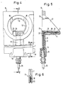
- Fig. 1 shows a schematic cross section of the top part of a cylinder of a direct injection internal-combustion engine according to the invention.
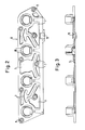
- Fig. 2 shows a top view of the plate used.
- Fig. 3 shows a front view of said plate.
- Fig. 4 shows a part of the top view shown in Fig. 2, on a larger scale, and with a current supply connector pin (part of the cover of a chamber is imagined cut away).
- Fig. 5 shows a cross section along the line V-V in Fig. 4.
- Fig. 6 shows a cross section along the line VI-VI in Fig. 4.
- The top part of an internal-combustion engine shown in Fig. has a cylinder head 1, on which an inlet tube 2 with fuel injector 3 is fixed. Inlet tube 2 opens out into an inlet channel 4 of the cylinder head. The inlet valve 5 is located in that channel.
- A plate 6 of heat-conducting material, for example an aluminium alloy, is clamped between the inlet tube 2 and the cylinder head 1. In the case shown in the drawing this plate is common to four cylinders.
- In order to pronounce the sealing faces and save material, recesses 7 are disposed in the plate and fixing holes 8 are also cut out in the plate.
- At each inlet channel 4 the plate is provided with an aperture, and into each of said apertures projects a chamber 11, which is at right angles to the surface of the gasket, and a
cylindrical surface 12 the width of which is at its maximum at the connection to the chamber 11 and at its minimum diagonally opposite. The cylindrical surface part of the lowest width is provided with arecess 13, through which the fuel injector projects. The top face of the chamber 11 and thecylindrical surface 12 form a heat sink. - A
PTC tablet 16 is provided in each chamber 11, being fixed to the upper wall of the chamber 11 by means of a heat and electricity conducting epoxy resin. Each chamber also contains acontact spring 15 which is insulated from the heat sink by means of plastic. - Each
contact spring 15 is connected, by means of aguide strip 14, aguide strip 17 connected thereto by laser welding and aguide strip 18 integral therewith, to aconnector pin 20 which projects into ajunction box 19. Thestrips insulating encasement strip 18 is soldered to thepin 20. - The chambers 11 are closed by a
cover 23 fixed bylaser welds 24. The combination of plate 6 and fuel elements connected thereto by conducting material bridges is placed between inlet tube 2 and inlet port of the cylinder head, agasket 6b of heat-conducting material such as an aluminium alloy being added at the cylinder head side, and agasket 6a of insulating material such as paper being added at the inlet tube side. When the engine is cold, effective heating of the injected fuel is achieved. This fuel is sprayed at various angles onto the top face of the chambers 11 belonging to the heat sinks. When current is supplied via thepin 20, thecurrent conductors contact springs 15, the tablets will be heated to a temperature value determined by the PTC material, and this heat will be passed on to the top face of the chambers 11. A rivet joint is indicated by 25. - Air is drawn into the inlet tube 2 in the direction of the arrows (Fig. 1). A streamlining element can be fitted on the
cover 23 of each chamber. Apart from such a cover, the PTC tablet in each chamber can also be shut off from the environment in a different way, for example by filling powder or epoxy resin. The interior of each chamber 11 is in connection with the atmosphere via the slit-type space in which thecurrent conductors - Various modifications of the device described are possible within the scope of the invention. What is important for the inventive idea is that the heating elements are not fitted in a thermally insulated manner, and are integrated in a plate which is clamped between the inlet nozzle and the cylinder head, each PTC tablet being disposed in a closed chamber whose top face forms part of the heat sink. It is not out of the question for a different electrical resistance material to be used instead of PTC tablets.
Claims (10)
Applications Claiming Priority (2)
| Application Number | Priority Date | Filing Date | Title |
|---|---|---|---|
| NL8801334 | 1988-05-24 | ||
| NL8801334A NL8801334A (en) | 1988-05-24 | 1988-05-24 | INJECTION TYPE OF COMBUSTION ENGINE, AND PLATE INTENDED TO BE INSTALLED BETWEEN THE INLET GATES OF A CYLINDER BLOCK OF SUCH ENGINE AND AN INJECTOR. |
Publications (2)
| Publication Number | Publication Date |
|---|---|
| EP0343652A1 true EP0343652A1 (en) | 1989-11-29 |
| EP0343652B1 EP0343652B1 (en) | 1993-07-21 |
Family
ID=19852345
Family Applications (1)
| Application Number | Title | Priority Date | Filing Date |
|---|---|---|---|
| EP89109419A Expired - Lifetime EP0343652B1 (en) | 1988-05-24 | 1989-05-24 | Internal combustion engine of the injection type, and plate intended for fitting between the inlet ports of a cylinder block of such an engine and an inlet tube |
Country Status (7)
| Country | Link |
|---|---|
| US (1) | US4967706A (en) |
| EP (1) | EP0343652B1 (en) |
| JP (2) | JPH0249962A (en) |
| KR (1) | KR940002959B1 (en) |
| DE (1) | DE68907647T2 (en) |
| ES (1) | ES2042876T3 (en) |
| NL (1) | NL8801334A (en) |
Cited By (13)
| Publication number | Priority date | Publication date | Assignee | Title |
|---|---|---|---|---|
| EP0404477A1 (en) * | 1989-06-20 | 1990-12-27 | Texas Instruments Incorporated | A fuel supply device and heating device |
| DE3943569A1 (en) * | 1989-12-07 | 1991-06-13 | Daimler Benz Ag | DEVICE FOR INCREASING THE PROCESS TEMPERATURE OF A PISTON PISTON COMBUSTION ENGINE |
| DE4020266C1 (en) * | 1990-06-26 | 1991-09-26 | Mercedes-Benz Aktiengesellschaft, 7000 Stuttgart, De | |
| DE4020267C1 (en) * | 1990-06-26 | 1991-10-24 | Mercedes-Benz Aktiengesellschaft, 7000 Stuttgart, De | |
| EP0453927A1 (en) * | 1990-04-17 | 1991-10-30 | Texas Instruments Holland B.V. | Injection internal combustion engine with electric spark ignition |
| EP0456533A1 (en) * | 1990-05-09 | 1991-11-13 | Automobiles Peugeot | Intake device for internal combustion engine with premixing |
| EP0456535A1 (en) * | 1990-05-10 | 1991-11-13 | Automobiles Peugeot | Intake device for a mixture inducing internal combustion engine |
| EP0469261A1 (en) * | 1990-07-28 | 1992-02-05 | Mercedes-Benz Ag | Suction device for a mixture compressing internal combustion engine |
| EP0472417A1 (en) * | 1990-08-22 | 1992-02-26 | Texas Instruments Incorporated | Internal combustion engine with fuel injectors and heaters |
| EP0472416A1 (en) * | 1990-08-22 | 1992-02-26 | Texas Instruments Incorporated | Internal combustion engine with fuel heaters |
| US5134986A (en) * | 1990-08-22 | 1992-08-04 | Texas Instruments Incorporated | Internal combustion engine with fuel heater |
| DE4216384C1 (en) * | 1992-05-18 | 1993-10-21 | Duerrwaechter E Dr Doduco | Device for heating a fuel-air mixture of an internal combustion engine with fuel injection |
| DE19511685C1 (en) * | 1995-03-30 | 1996-11-21 | Freudenberg Carl Fa | Heating module for an internal combustion engine |
Families Citing this family (13)
| Publication number | Priority date | Publication date | Assignee | Title |
|---|---|---|---|---|
| NL9002129A (en) * | 1990-09-28 | 1992-04-16 | Texas Instruments Holland | INJECTION COMBUSTION ENGINE WITH ELECTRIC SPARK IGNITION AND HEATING DEVICE. |
| US5115787A (en) * | 1991-09-24 | 1992-05-26 | Texas Instruments Incorporated | Spark ignition combustion engine of the fuel injection type and heating element therefor |
| JPH05180124A (en) * | 1992-01-07 | 1993-07-20 | Mitsubishi Electric Corp | Fuel supply device for gasoline internal combustion engine |
| US5284117A (en) * | 1992-04-27 | 1994-02-08 | Mitsubishi Denki Kabushiki Kaisha | Fuel supply apparatus for an internal combustion engine |
| SE470322B (en) * | 1992-07-07 | 1994-01-17 | Saab Automobile | Device and method for controlling fuel injection start in an internal combustion engine |
| JPH0688560A (en) * | 1992-09-04 | 1994-03-29 | Texas Instr Japan Ltd | Fuel supply control device for internal combustion engine |
| DE4314283C2 (en) * | 1993-04-30 | 1995-04-13 | Freudenberg Carl Fa | Heating module for an internal combustion engine |
| DE19638323A1 (en) * | 1996-09-19 | 1998-04-02 | Daimler Benz Ag | Method for operating an internal combustion engine and internal combustion engine |
| US6298834B1 (en) * | 1998-04-22 | 2001-10-09 | Safe Energy Systems, Inc. | Fuel vaporizing attachment for liquid fueled internal combustion engines |
| US20090241905A1 (en) * | 2006-03-29 | 2009-10-01 | Denso Corporation | Mount structure of fuel injection valve and fuel injection system |
| DE102006039973A1 (en) * | 2006-08-25 | 2008-02-28 | Bayerische Motoren Werke Ag | Device and method for providing a fuel-air mixture for an internal combustion engine |
| CN215170416U (en) * | 2018-11-22 | 2021-12-14 | 株式会社爱信 | Intake device for internal combustion engine |
| JP2020125687A (en) | 2019-02-01 | 2020-08-20 | アイシン精機株式会社 | Intake device for internal combustion engine |
Citations (5)
| Publication number | Priority date | Publication date | Assignee | Title |
|---|---|---|---|---|
| US3760780A (en) * | 1971-08-12 | 1973-09-25 | W Jordan | Electric heating means for fuel vaporization in internal combustion engines |
| US4387291A (en) * | 1980-11-28 | 1983-06-07 | Texas Instruments Incorporated | Fuel heater system and self-regulating heater therefor |
| DE3247978A1 (en) * | 1982-12-24 | 1984-06-28 | Günter 3300 Braunschweig Siebensohn | Method for mixture preparation in a spark ignition engine and spark ignition engine for performing the method |
| DE3426469C2 (en) * | 1984-07-18 | 1986-05-28 | Daimler-Benz Ag, 7000 Stuttgart | Intake system for a mixture-compressing internal combustion engine |
| EP0234052A1 (en) * | 1986-02-20 | 1987-09-02 | Texas Instruments Holland B.V. | Liquid heating device |
Family Cites Families (12)
| Publication number | Priority date | Publication date | Assignee | Title |
|---|---|---|---|---|
| US3145699A (en) * | 1962-01-22 | 1964-08-25 | Carl F High | Fuel injection engine |
| JPS5623563A (en) * | 1979-08-01 | 1981-03-05 | Toyota Motor Corp | Fuel injecting carburetor |
| JPS5652562U (en) * | 1979-09-29 | 1981-05-09 | ||
| JPS56127866U (en) * | 1980-02-29 | 1981-09-29 | ||
| JPS57172155U (en) * | 1981-04-24 | 1982-10-29 | ||
| JPS5811350U (en) * | 1981-07-15 | 1983-01-25 | 松下電工株式会社 | wireless intercom |
| JPS58111350U (en) * | 1982-01-22 | 1983-07-29 | 日産自動車株式会社 | Fuel vaporization accelerator for internal combustion engines |
| JPS5918133U (en) * | 1982-07-22 | 1984-02-03 | 勝見 礼三 | Combustion equipment in old tire incinerator |
| JPS59146562U (en) * | 1983-03-22 | 1984-09-29 | 三菱自動車工業株式会社 | Engine intake air heating device |
| JPS59148461U (en) * | 1983-03-25 | 1984-10-04 | ティーディーケイ株式会社 | Internal combustion engine intake air heating device |
| JPS61145867U (en) * | 1985-03-01 | 1986-09-09 | ||
| NL8602782A (en) * | 1986-11-03 | 1988-06-01 | Texas Instruments Holland | COMBUSTION ENGINE. |
-
1988
- 1988-05-24 NL NL8801334A patent/NL8801334A/en not_active Application Discontinuation
-
1989
- 1989-05-09 US US07/349,246 patent/US4967706A/en not_active Expired - Fee Related
- 1989-05-23 JP JP1129959A patent/JPH0249962A/en active Granted
- 1989-05-24 EP EP89109419A patent/EP0343652B1/en not_active Expired - Lifetime
- 1989-05-24 DE DE89109419T patent/DE68907647T2/en not_active Expired - Fee Related
- 1989-05-24 KR KR1019890006915A patent/KR940002959B1/en not_active Expired - Fee Related
- 1989-05-24 ES ES89109419T patent/ES2042876T3/en not_active Expired - Lifetime
-
1994
- 1994-05-16 JP JP6101318A patent/JP2502945B2/en not_active Expired - Lifetime
Patent Citations (5)
| Publication number | Priority date | Publication date | Assignee | Title |
|---|---|---|---|---|
| US3760780A (en) * | 1971-08-12 | 1973-09-25 | W Jordan | Electric heating means for fuel vaporization in internal combustion engines |
| US4387291A (en) * | 1980-11-28 | 1983-06-07 | Texas Instruments Incorporated | Fuel heater system and self-regulating heater therefor |
| DE3247978A1 (en) * | 1982-12-24 | 1984-06-28 | Günter 3300 Braunschweig Siebensohn | Method for mixture preparation in a spark ignition engine and spark ignition engine for performing the method |
| DE3426469C2 (en) * | 1984-07-18 | 1986-05-28 | Daimler-Benz Ag, 7000 Stuttgart | Intake system for a mixture-compressing internal combustion engine |
| EP0234052A1 (en) * | 1986-02-20 | 1987-09-02 | Texas Instruments Holland B.V. | Liquid heating device |
Cited By (21)
| Publication number | Priority date | Publication date | Assignee | Title |
|---|---|---|---|---|
| EP0404477A1 (en) * | 1989-06-20 | 1990-12-27 | Texas Instruments Incorporated | A fuel supply device and heating device |
| DE3943569A1 (en) * | 1989-12-07 | 1991-06-13 | Daimler Benz Ag | DEVICE FOR INCREASING THE PROCESS TEMPERATURE OF A PISTON PISTON COMBUSTION ENGINE |
| EP0453927A1 (en) * | 1990-04-17 | 1991-10-30 | Texas Instruments Holland B.V. | Injection internal combustion engine with electric spark ignition |
| EP0456533A1 (en) * | 1990-05-09 | 1991-11-13 | Automobiles Peugeot | Intake device for internal combustion engine with premixing |
| FR2661951A1 (en) * | 1990-05-09 | 1991-11-15 | Peugeot | INTAKE DEVICE FOR AN INTERNAL COMBUSTION ENGINE WITH PREMIXING GAS. |
| EP0456535A1 (en) * | 1990-05-10 | 1991-11-13 | Automobiles Peugeot | Intake device for a mixture inducing internal combustion engine |
| FR2661952A1 (en) * | 1990-05-10 | 1991-11-15 | Peugeot | INTAKE DEVICE FOR AN INTERNAL COMBUSTION ENGINE WITH PREMIXING GAS. |
| DE4020266C1 (en) * | 1990-06-26 | 1991-09-26 | Mercedes-Benz Aktiengesellschaft, 7000 Stuttgart, De | |
| DE4020267C1 (en) * | 1990-06-26 | 1991-10-24 | Mercedes-Benz Aktiengesellschaft, 7000 Stuttgart, De | |
| US5152272A (en) * | 1990-06-26 | 1992-10-06 | Mercedes-Benz Ag | Cylinder head with an evaporation element in an air-intake channel |
| DE4024005A1 (en) * | 1990-07-28 | 1992-02-06 | Daimler Benz Ag | SUCTION DEVICE FOR A MIX-COMPRESSING INTERNAL COMBUSTION ENGINE |
| EP0469261A1 (en) * | 1990-07-28 | 1992-02-05 | Mercedes-Benz Ag | Suction device for a mixture compressing internal combustion engine |
| US5154154A (en) * | 1990-07-28 | 1992-10-13 | Mercedes-Benz Aktiengesellschaft | Intake device for a mixture-compressing internal-combustion engine |
| EP0472417A1 (en) * | 1990-08-22 | 1992-02-26 | Texas Instruments Incorporated | Internal combustion engine with fuel injectors and heaters |
| EP0472416A1 (en) * | 1990-08-22 | 1992-02-26 | Texas Instruments Incorporated | Internal combustion engine with fuel heaters |
| US5134986A (en) * | 1990-08-22 | 1992-08-04 | Texas Instruments Incorporated | Internal combustion engine with fuel heater |
| DE4216384C1 (en) * | 1992-05-18 | 1993-10-21 | Duerrwaechter E Dr Doduco | Device for heating a fuel-air mixture of an internal combustion engine with fuel injection |
| EP0570919A1 (en) * | 1992-05-18 | 1993-11-24 | DODUCO GMBH + Co Dr. Eugen DÀ¼rrwächter | Device for heating a fuel-air-mixture of an internal combustion engine with fuel injection |
| DE19511685C1 (en) * | 1995-03-30 | 1996-11-21 | Freudenberg Carl Fa | Heating module for an internal combustion engine |
| EP0735265A3 (en) * | 1995-03-30 | 1997-04-02 | Freudenberg Carl Fa | Heating device for a combustion engine |
| US5642695A (en) * | 1995-03-30 | 1997-07-01 | Firma Carl Freudenberg | Heating module for a combustion engine |
Also Published As
| Publication number | Publication date |
|---|---|
| US4967706A (en) | 1990-11-06 |
| KR890017452A (en) | 1989-12-16 |
| JPH0529784B2 (en) | 1993-05-06 |
| EP0343652B1 (en) | 1993-07-21 |
| JPH06341354A (en) | 1994-12-13 |
| ES2042876T3 (en) | 1993-12-16 |
| DE68907647D1 (en) | 1993-08-26 |
| NL8801334A (en) | 1989-12-18 |
| JP2502945B2 (en) | 1996-05-29 |
| KR940002959B1 (en) | 1994-04-09 |
| DE68907647T2 (en) | 1993-12-16 |
| JPH0249962A (en) | 1990-02-20 |
Similar Documents
| Publication | Publication Date | Title |
|---|---|---|
| US4967706A (en) | Internal-combustion engine of the injection type, and plate intended for fitting between the inlet ports of a cylinder block of such an engine and an inlet tube | |
| EP0247697B1 (en) | Spray valve for a combustion engine | |
| US5401935A (en) | Fuel heating assembly | |
| US5050569A (en) | Fuel injection system for an internal combustion engine and fuel heating device therefor | |
| US20150300300A1 (en) | Preheating device for a fuel injection system | |
| US6325053B1 (en) | Intake system for an internal combustion engine | |
| US20040025852A1 (en) | Heating device and engine drive method | |
| EP0267645A1 (en) | Internal combustion enginewith heating means for heating the fuel/air mixture | |
| US5086747A (en) | Internal combustion engine with fuel heater | |
| EP0453927B1 (en) | Injection internal combustion engine with electric spark ignition | |
| GB2064658A (en) | Heating of combustible mixture generators for internal combustion engines | |
| US5115787A (en) | Spark ignition combustion engine of the fuel injection type and heating element therefor | |
| EP0478091A1 (en) | Injection internal combustion engine with electrical spark ignition and heating unit | |
| US5438969A (en) | Heating module for an internal combustion engine | |
| US6279549B1 (en) | Heater for a cold start fuel injector | |
| EP0594794B1 (en) | Injection combustion engine with fuel heating element | |
| US5134986A (en) | Internal combustion engine with fuel heater | |
| WO1997019265A3 (en) | Fuel pre-heater | |
| EP0661445B1 (en) | Injection internal combustion engine with fuel heating element and adjustable fuel directing device | |
| EP1102007B1 (en) | Glow-plug | |
| JPS6217357A (en) | Fuel heater for internal-combustion engine | |
| JPH01195962A (en) | Fluid supplier and heating element thereof | |
| JPH0522122B2 (en) | ||
| JPS6365212A (en) | Vaporizing device for liquid fuel | |
| JPS62218652A (en) | Fuel heating device |
Legal Events
| Date | Code | Title | Description |
|---|---|---|---|
| PUAI | Public reference made under article 153(3) epc to a published international application that has entered the european phase |
Free format text: ORIGINAL CODE: 0009012 |
|
| AK | Designated contracting states |
Kind code of ref document: A1 Designated state(s): DE ES FR GB IT NL |
|
| 17P | Request for examination filed |
Effective date: 19891207 |
|
| 17Q | First examination report despatched |
Effective date: 19910213 |
|
| GRAA | (expected) grant |
Free format text: ORIGINAL CODE: 0009210 |
|
| ITF | It: translation for a ep patent filed | ||
| AK | Designated contracting states |
Kind code of ref document: B1 Designated state(s): DE ES FR GB IT NL |
|
| REF | Corresponds to: |
Ref document number: 68907647 Country of ref document: DE Date of ref document: 19930826 |
|
| ET | Fr: translation filed | ||
| REG | Reference to a national code |
Ref country code: ES Ref legal event code: FG2A Ref document number: 2042876 Country of ref document: ES Kind code of ref document: T3 |
|
| PLBE | No opposition filed within time limit |
Free format text: ORIGINAL CODE: 0009261 |
|
| STAA | Information on the status of an ep patent application or granted ep patent |
Free format text: STATUS: NO OPPOSITION FILED WITHIN TIME LIMIT |
|
| 26N | No opposition filed | ||
| PGFP | Annual fee paid to national office [announced via postgrant information from national office to epo] |
Ref country code: FR Payment date: 19970226 Year of fee payment: 9 |
|
| PGFP | Annual fee paid to national office [announced via postgrant information from national office to epo] |
Ref country code: ES Payment date: 19970505 Year of fee payment: 9 Ref country code: DE Payment date: 19970505 Year of fee payment: 9 |
|
| PGFP | Annual fee paid to national office [announced via postgrant information from national office to epo] |
Ref country code: GB Payment date: 19970515 Year of fee payment: 9 |
|
| PGFP | Annual fee paid to national office [announced via postgrant information from national office to epo] |
Ref country code: NL Payment date: 19970531 Year of fee payment: 9 |
|
| PG25 | Lapsed in a contracting state [announced via postgrant information from national office to epo] |
Ref country code: GB Free format text: LAPSE BECAUSE OF NON-PAYMENT OF DUE FEES Effective date: 19980524 |
|
| PG25 | Lapsed in a contracting state [announced via postgrant information from national office to epo] |
Ref country code: ES Free format text: LAPSE BECAUSE OF EXPIRATION OF PROTECTION Effective date: 19980525 |
|
| PG25 | Lapsed in a contracting state [announced via postgrant information from national office to epo] |
Ref country code: FR Free format text: LAPSE BECAUSE OF NON-PAYMENT OF DUE FEES Effective date: 19980531 |
|
| PG25 | Lapsed in a contracting state [announced via postgrant information from national office to epo] |
Ref country code: NL Free format text: LAPSE BECAUSE OF NON-PAYMENT OF DUE FEES Effective date: 19981201 |
|
| GBPC | Gb: european patent ceased through non-payment of renewal fee |
Effective date: 19980524 |
|
| NLV4 | Nl: lapsed or anulled due to non-payment of the annual fee |
Effective date: 19981201 |
|
| PG25 | Lapsed in a contracting state [announced via postgrant information from national office to epo] |
Ref country code: DE Free format text: LAPSE BECAUSE OF NON-PAYMENT OF DUE FEES Effective date: 19990302 |
|
| REG | Reference to a national code |
Ref country code: FR Ref legal event code: ST |
|
| REG | Reference to a national code |
Ref country code: ES Ref legal event code: FD2A Effective date: 20000201 |
|
| PG25 | Lapsed in a contracting state [announced via postgrant information from national office to epo] |
Ref country code: IT Free format text: LAPSE BECAUSE OF NON-PAYMENT OF DUE FEES;WARNING: LAPSES OF ITALIAN PATENTS WITH EFFECTIVE DATE BEFORE 2007 MAY HAVE OCCURRED AT ANY TIME BEFORE 2007. THE CORRECT EFFECTIVE DATE MAY BE DIFFERENT FROM THE ONE RECORDED. Effective date: 20050524 |