EP0468571B1 - Hydraulically propelled pneumatically returned valve actuator - Google Patents
Hydraulically propelled pneumatically returned valve actuator Download PDFInfo
- Publication number
- EP0468571B1 EP0468571B1 EP91201850A EP91201850A EP0468571B1 EP 0468571 B1 EP0468571 B1 EP 0468571B1 EP 91201850 A EP91201850 A EP 91201850A EP 91201850 A EP91201850 A EP 91201850A EP 0468571 B1 EP0468571 B1 EP 0468571B1
- Authority
- EP
- European Patent Office
- Prior art keywords
- valve
- piston
- mechanism portion
- chamber
- air
- Prior art date
- Legal status (The legal status is an assumption and is not a legal conclusion. Google has not performed a legal analysis and makes no representation as to the accuracy of the status listed.)
- Expired - Lifetime
Links
Images


Classifications
-
- F—MECHANICAL ENGINEERING; LIGHTING; HEATING; WEAPONS; BLASTING
- F01—MACHINES OR ENGINES IN GENERAL; ENGINE PLANTS IN GENERAL; STEAM ENGINES
- F01L—CYCLICALLY OPERATING VALVES FOR MACHINES OR ENGINES
- F01L9/00—Valve-gear or valve arrangements actuated non-mechanically
- F01L9/10—Valve-gear or valve arrangements actuated non-mechanically by fluid means, e.g. hydraulic
Definitions
- the present invention relates to an asymmetrical bistable hydraulically powered actuator mechanism comprising a replenishable source of high pressure hydraulic fluid for causing translation of a portion of the mechanism from an initial position in one direction; a first damping chamber in which air is compressed during translation of the mechanism portion in said one direction, compression of the air slowing the translation in said one direction of the mechanism portion; means for temporarily preventing reversal of the direction of translation of the mechanism portion when the translation of the mechanism portion slows to a stop; means operable on command for disabling the temporarily preventing means so as to free the mechanism portion and move the mechanism portion in a direction opposite said one direction under the influence of the pressure of the air compressed in the first damping chamber; and a second damping chamber in which air is compressed during the translation of the mechanism portion in the direction opposite said one direction for damping and slowing the translation of the mechanism portion as it returns to the initial position.
- the invention also relates to an electronically controllable valve mechanism comprising an engine intake or exhaust valve, which is suitable for use in an internal combustion engine and is provided with an elongated valve stem, wherein the valve stem is moveable in the direction of stem elongation by an asymmetrical bistable hydraulically powered actuator mechanism according to the invention.
- EP-A-0 352 861 there is disclosed a computer control system which receives a plurality of engine operation sensor inputs and in turn controls a plurality of engine operating parameters including ignition timing and the time in each cycle of the opening and closing of the intake and exhaust valves among others.
- U.S. Patent 4,009,695 discloses hydraulically actuated valves in turn controlled by spool valves which are themselves controlled by a dashboard computer which monitors a number of engine operating parameters.
- This patent references many advantages which could be achieved by such independent valve control, but is not, due to its relatively slow acting hydraulic nature, capable of achieving these advantages.
- the patented arrangement attempts to control the valves on a real time basis so that the overall system is one with feedback and subject to the associated oscillatory behaviour.
- EP-A-0 328 195 there is disclosed a somewhat similar valve actuating device which employs a release type mechanism rather than a repulsion scheme as in the previously identified U.S. Patent.
- the disclosed device in this application is a jointly pneumatically and electromagnetically powered valve with high pressure air supply and control valving to use the air for both damping and as one motive force.
- the magnetic motive force is supplied from the magnetic latch opposite the one being released and this magnetic force attracts an armature of the device so long as the magnetic field of the first latch is in its reduced state. As the armature closes on the opposite latch, the magnetic attraction increases and overpowers that of the first latch regardless of whether it remains in the reduced state or not.
- a main or working piston which drives the engine valve and which is, in turn powered by compressed air.
- the power or working piston which moves the engine valve between open and closed positions is separated from the latching components and certain control valving structures so that the mass to be moved is materially reduced allowing very rapid operation. Latching and release forces are also reduced. Those valving components which have been separated from the main piston need not travel the full length of the piston stroke, leading to some improvement in efficiency.
- Compressed air is supplied to the working piston by a pair of control valves with that compressed air driving the piston from one position to another as well as typically holding the piston in a given position until a control valve is again actuated.
- the control valves are held closed by permanent magnets and opened by pneumatic force on the control valve when an electrical pulse to a coil near the permanent magnet neutralizes the attractive force of the magnet.
- EP-A-0 443 218 there is disclosed a hydraulically powered valve actuating mechanism including, inter alia, a high presuure hydraulic fluid accumulator in close proximity to the cavity in which the fluid is to do its work. It is somewhere between inefficient and impossible to move hydraulic fluid over a wide temperature range rapidly through long lines of relatively small cross-section.
- This application provides a chamber expandable against spring-loaded pistons in very close proximity to the working chamber of the actuator to which high pressure fluid is continuously supplied and from which a larger volume of fluid may be efficiently intermittently removed.
- an actuator piston is propelled from a valve-closed toward a valve-pen position and utilizes the air which is compressed during the damping process to power the actuator back to its initial or valve-closed position.
- an actuator capture or latching arrangement such as a hydraulic latch, is used in this recent invention to assure that the actuator does not immediately rebound, but rather remains in the valve-open position until commanded to return to its initial position.
- the initial translation of the actuator piston in this recent application is powered by pneumatic energy and requires a relatively large source pump as well as relatively large individual valve actuators.
- An asymmetrical bistable hydraulically powered actuator mechanism as mentioned in the opening paragraph is known from DE-A-31 39 399.
- the known actuator mechanism serves to actuate an engine inlet or exhaust valve in an internal combustion engine.
- the air which is compressed in the first damping chamber, acts on a piston fixed to a valve stem to bias the valve to its initial position in which a valve head is pressed against a valve seat.
- this compressed air acts as a stressed return spring tending to return the valve to its initial position with the valve head in contact with the valve scat.
- air is compressed in the second damping chamber, so that the valve is slowed as it returns to its initial position.
- a disadvantage of this known mechanism is that the damping force of the second damping chamber is not accurately determined as a function of the position of the valve head, so that the valve head or the valve seat may be damaged when the valve is returned to its initial position by the compressed air.
- an asymmetrical bistable valve actuator of improved design the provision of a hydraulically driven, pneumatically returned valve actuator; the provision of an increased pressure, reduced size hydraulic capture arrangement for temporarily delaying the return of an internal combustion engine to its valve-closed position; the provision of individually adjustable dual damping features in a valve actuator; and an arrangement in an internal combustion engine valve actuator for easing the valve gently yet solidly into its valve-closed position.
- the asymmetrical bistable hydraulically powered actuator mechanism is characterized in that the mechanism further comprises a first adjustable aperture allowing air to escape from the second damping chamber during less than the entire travel of the mechanism portion back to the initial position and a second adjustable aperture for allowing air to escape from the second damping chamber during the entire travel of the mechanism portion back to the initial position.
- first and second adjustable apertures By the use of said first and second adjustable apertures the mechanism portion smoothly returns to the initial position.
- the coaction of the first and second apertures provides a preliminary mild damping of the motion of the mechanism portion and the subsequent action of the second aperture only provides a more severe final damping of the mechanism portion motion. In this way, a controlled damping of the mechanism portion motion is achieved when the mechanism portion returns into the initial position, so that damage of the valve coupled to the mechanism portion or of the valve seat is avoided as much as possible.
- an asymmetrical bistable hydraulically powered actuator mechanism which comprises a second damping chamber for slowing the mechanism portion as it returns to the initial position
- EP-A-0 391 507 European patent application EP-A-0 391 507, which was published after the priority date of the present application but has a priority date before the priority date of the present application.
- pressure is exerted upon a hydraulic fluid as the mechanism portion returns to its initial position.
- the present invention takes advantage of many of the developments disclosed in the copending application EP-A-0 468 548 while the initial powered translation is accomplished by hydraulic energy from a hydraulic pump rather than by pneumatic energy.
- Hydraulic energy propulsion yields the advantages of reduced actuator size and, therefore, is easier to package, as well as a reduction of the size of and, therefore, the space required underneath a vehicle hood by the hydraulic pump.
- the compression of latching air and pneumatic energy recovery feature is accomplished in a smaller chamber than taught in copending application EP-A-0 468 548.
- the reduction in size is accompanied by a correlative increase in peak pressure of the compressed air.
- the latching pressure must be correspondingly increased, and in particular, a decrease in piston diameter to one-half the former value requires a corresponding four-fold increase in pressure to maintain the same overall latching force.
- the present invention also utilizes a third chamber behind the energy recovery piston which functions as the primary damping chamber for piston motion near the end of its return trip to the valve-closed position. It is not only important to damp piston motion as the internal combustion engine valve nears its closed position allowing the valve to gracefully close, it is also important to insure that the valve is fully and positively seated.
- a dual damping function with an arrangement for individually adjusting each step of the damping process assures gentle seating of the engine poppet valve.
- the present invention utilizes a closely coupled fluid accumulator to assure a rapid flow of the non-compressible fluid into the actuator.
- a bladder type accumulator with the fluid supply therein being continuously replenished and with the fluid supply being refilled or catching up between actuator translations is utilized along with a low viscosity, high viscosity index fluid having a broad temperature range to insure rapid response under a wide range of conditions as the fluid travels from the accumulator, through a one-way valve and into the actuator.
- a spring loaded high pressure accumulator as disclosed in the above-mentioned application EP-A-0 443 218 may be employed.
- a bistable electronically controlled hydraulically powered transducer has an armature which is reciprocable between first and second positions along with a hydraulic arrangement for powering the armature from the first position to the second position.
- armature which is reciprocable between first and second positions along with a hydraulic arrangement for powering the armature from the first position to the second position.
- pneumatic energy storage chamber in which air is compressed during motion of the armature from the first position to the second position with the compression of the air damping or slowing armature motion as it nears the second position.
- Reversal of armature motion when the motion of the armature has slowed to a stop is temporarily prevented by a hydraulic latch which is disableable on command to allow the air compressed in the chamber to return the armature to the first position.
- the hydraulic latch and the hydraulic powering arrangement may utilize the same hydraulic chamber.
- This controlled venting of air from the second chamber is achieved by a first adjustable aperture which allows air to escape from the chamber during less than the entire travel of the armature back from the second position to the first position, and a second adjustable aperture which allows air to escape from the chamber the entire time the armature is travelling back to the first position.
- These two apertures act together to provide a preliminary mild damping of armature motion.
- the first aperture is closed by armature motion part way through the transition and subsequent action of the second aperture by itself provides a more severe final damping of the armature motion.
- There is a hydraulic fluid accumulator located in close proximity to the area of the armature which is powered by the fluid for continuously receiving high pressure fluid and intermittently supplying fluid to power the armature. The closely adjacent accumulator insures a rapid, low loss response by the armature.
- the piston is hydraulic unilaterally moved, thereby causing the engine valve to move in the direction of stem elongation from a valve-closed to a valve-open position.
- the hydraulic source for powering the piston may include a hydraulic fluid accumulator in close proximity to the area of the piston for continuously receiving high pressure fluid and intermittently supplying fluid to power the piston.
- a pneumatic damping arrangement is provided for compressing a volume of air and imparting a continuously increasing decelerating force as the engine valve approaches the valve-open position. Finally, the compressed volume of air is utilized on command to power the piston back to the valve-closed position.
- the present invention utilizes hydraulic fluid to power an actuator from an initial position to a second position.
- the invention takes advantage of the concepts disclosed in the above-mentioned copending application EP-A-0 468 548 wherein a precise quantity of air is trapped, compressed and stored on the obverse side of the actuator piston as that piston nears its second (valve-open) position.
- the compressed air and its associated potential energy is stored by locking or capturing the piston shaft by a fluid latch which is made an integral part of the hydraulic system.
- the actuator may then be commanded to return to the first position by releasing the latching fluid allowing the stored compressed air to return the actuator to the valve-closed position.
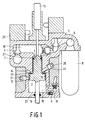
- Figure 1 shows the actuator in its first or rest position in which the engine valve is closed.
- the shaft 16 connects to a conventional internal combustion engine poppet valve (not shown).
- a ball valve 3 is opened by a solenoid the high pressure hydraulic fluid in the accumulator 8 quickly forces the ball valve 5 open and applies high pressure to the hydraulic subpiston 1.
- the high pressure causes the subpiston 1 and its interconnected piston 2 to move downwards.
- This subpiston is formed as the upper portion including the reduced diameter face of the power piston 2.
- These two pistons 1 and 2 may be physically formed from the same piece of material as a piston assembly, yet are isolated from one another by leakproof seals 19, 21 and 23.
- Figure 4 illustrates the actuator just after the piston assembly has reached its lowest position.
- the very high pressure air in chamber 15 has displaced the piston 2 back slightly upwards to compress the fluid in chamber 18 to a pressure higher than the system pressure as supplied from the accumulator 8.
- Pressure in chamber 18 above the system pressure causes one-way valve 5 to re-close effectively latching the piston assembly and preventing any further rebound toward its initial or first position.
- Accumulator 8 is also being recharged while the piston assembly rests in the location of Figure 4 by way of hydraulic fluid inlet port 6.
- Figure 5 shows the actuator with the piston assembly in its lower stable position. The difference between Figures 4 and 5 is that all valves are now closed and the fluid in chamber 18 is holding the piston assembly from any motion back upwards due to the very high pressure urging of the air in chamber 15. Also in Figure 5, the replenishing of the accumulator 8 fluid supply is nearly completed.
- Figure 7 illustrates the point in the piston assembly return trip where initial damping has been completed and the piston seal 19 has just closed off the port to orifice 12. Up to this point, damping of upward motion has been determined by the controlled egress of air from the chamber 17 through both apertures 11 and 12, but, since seal 19 has now covered the opening to aperture 12, the damping is increased and fluid now exits more slowly through aperture 11 only.
- the size of aperture 11 controls the final damping to assure gentle seating of the poppet valve as the actuator piston assembly reaches its starting or initial position as illustrated in Figure 1.
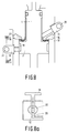
- Figure 8 illustrates in greater detail the dual stage controlled damping used to control the critical seating of the poppet valve.
- an air manifold 14 disposed about at least a substantial portion of the periphery of the cylinder which feeds air through a multi-vane reed valve 27. This allows entry of air into chamber 17 during downward movement of the piston assembly in a miner virtually free of any throttling retardation or losses.
- the reed valve closes and air must escape chamber 17 through the apertures 11 and 12.
- Adjustable needle valves 29 and 31 are located adjacent and movable into the orifices 11 and 12 for the precise adjustment of the size of these air escapement openings and therefore also of the initial and final damping respectively.
- the aperture 30 extends through the piston wall and communicates with chamber 17 when the piston 2 is in suitable positions such as shown, for example, in Figure 3.
- the screw or needle portion of needle valve 31 extends orthogonally to this aperture and seats in a conical seat 33.
- the separation between the end of the needle and the conical seat defines the size of the aperture and may be varied as the screw is moved in or out.
- many other types of adjustable apertures may be employed.
Description
- The present invention relates to an asymmetrical bistable hydraulically powered actuator mechanism comprising a replenishable source of high pressure hydraulic fluid for causing translation of a portion of the mechanism from an initial position in one direction; a first damping chamber in which air is compressed during translation of the mechanism portion in said one direction, compression of the air slowing the translation in said one direction of the mechanism portion; means for temporarily preventing reversal of the direction of translation of the mechanism portion when the translation of the mechanism portion slows to a stop; means operable on command for disabling the temporarily preventing means so as to free the mechanism portion and move the mechanism portion in a direction opposite said one direction under the influence of the pressure of the air compressed in the first damping chamber; and a second damping chamber in which air is compressed during the translation of the mechanism portion in the direction opposite said one direction for damping and slowing the translation of the mechanism portion as it returns to the initial position.
- The invention also relates to an electronically controllable valve mechanism comprising an engine intake or exhaust valve, which is suitable for use in an internal combustion engine and is provided with an elongated valve stem, wherein the valve stem is moveable in the direction of stem elongation by an asymmetrical bistable hydraulically powered actuator mechanism according to the invention.
- The prior art has recognized numerous advantages which might be achieved by replacing the conventional mechanical cam actuated valve arrangements in internal combustion engines with other types of valve opening mechanisms which could be controlled in their opening and closing as a function of engine speed as well as engine crankshaft angular position or other engine parameters.
- For example, in EP-A-0 352 861 there is disclosed a computer control system which receives a plurality of engine operation sensor inputs and in turn controls a plurality of engine operating parameters including ignition timing and the time in each cycle of the opening and closing of the intake and exhaust valves among others.
- U.S. Patent 4,009,695 discloses hydraulically actuated valves in turn controlled by spool valves which are themselves controlled by a dashboard computer which monitors a number of engine operating parameters. This patent references many advantages which could be achieved by such independent valve control, but is not, due to its relatively slow acting hydraulic nature, capable of achieving these advantages. The patented arrangement attempts to control the valves on a real time basis so that the overall system is one with feedback and subject to the associated oscillatory behaviour.
- U.S. Patent 4,700,684 suggests that if freely adjustable opening and closing times for inlet and exhaust valves are available, then unthrottled load control is achievable by controlling exhaust gas retention within the cylinders.
- Substitutes for or improvements on conventional cam actuated valves have long been a goal. In U.S. Patent 4,794,890 there is disclosed a valve actuator which has permanent magnet latching at the open and closed positions. Electromagnetic repulsion may be employed to cause the valve to move from one position to the other. Several damping and energy recovery schemes are also included.
- In EP-A-0 328 195 there is disclosed a somewhat similar valve actuating device which employs a release type mechanism rather than a repulsion scheme as in the previously identified U.S. Patent. The disclosed device in this application is a jointly pneumatically and electromagnetically powered valve with high pressure air supply and control valving to use the air for both damping and as one motive force. The magnetic motive force is supplied from the magnetic latch opposite the one being released and this magnetic force attracts an armature of the device so long as the magnetic field of the first latch is in its reduced state. As the armature closes on the opposite latch, the magnetic attraction increases and overpowers that of the first latch regardless of whether it remains in the reduced state or not.
- The foregoing as well as a number of other related applications all assigned to the assignee of the present invention and filed in the name of William E. Richeson or William E. Richeson and Frederick L. Erickson are summarized in the introductory portions of EP-A-0 377 250.
- Many of the later filed above noted cases disclose a main or working piston which drives the engine valve and which is, in turn powered by compressed air. The power or working piston which moves the engine valve between open and closed positions is separated from the latching components and certain control valving structures so that the mass to be moved is materially reduced allowing very rapid operation. Latching and release forces are also reduced. Those valving components which have been separated from the main piston need not travel the full length of the piston stroke, leading to some improvement in efficiency. Compressed air is supplied to the working piston by a pair of control valves with that compressed air driving the piston from one position to another as well as typically holding the piston in a given position until a control valve is again actuated. The control valves are held closed by permanent magnets and opened by pneumatic force on the control valve when an electrical pulse to a coil near the permanent magnet neutralizes the attractive force of the magnet.
- An electronically controlled pneumatically powered actuator as described in U.S. Patent 4,825,528 has demonstrated very rapid transit times and infinite precise controllability. Devices constructed in accordance with this patent are capable of obtaining optimum performance from an internal combustion engine due to their ability to open and then independently close the poppet valves at any selectable crank shaft angles. In this prior patent arrangement, a source of high pressure air is required for both opening and for closing the valves. Moreover, such devices require a certain amount of duplication of structure in that symmetrical propulsion, exhaust air release, and regulated latching pressure (damping air) arrangements are needed. In this prior art configuration, substantially the same volume of air must be used to close the valve as was required to open it.
- In the devices of these applications, air is compressed by piston motion to slow the piston (dampen piston motion) near the end of its stroke and then that air is abruptly vented to atmosphere. When the piston is slowed or damped, its kinetic energy is converted to some other form of energy and in cases such as dumping the air compressed during damping to atmosphere, that energy is simply lost. U.S. Patents 4,883,025 and 4,831,973 disclose symmetric bistable actuators which attempt to recapture some of the piston kinetic energy as either stored compressed air or as a stressed mechanical spring which stored energy is subsequently used to power the piston on its return trip. In either of these patented devices, the energy storage device is symmetric and is releasing its energy to power the piston during the first half of each translation of the piston and is consuming piston kinetic energy during the second half of the same translation regardless of the direction of piston motion.
- In EP-A-0 443 218 there is disclosed a hydraulically powered valve actuating mechanism including, inter alia, a high presuure hydraulic fluid accumulator in close proximity to the cavity in which the fluid is to do its work. It is somewhere between inefficient and impossible to move hydraulic fluid over a wide temperature range rapidly through long lines of relatively small cross-section. This application provides a chamber expandable against spring-loaded pistons in very close proximity to the working chamber of the actuator to which high pressure fluid is continuously supplied and from which a larger volume of fluid may be efficiently intermittently removed.
- In copending application EP-A-0 468 548 an actuator piston is propelled from a valve-closed toward a valve-pen position and utilizes the air which is compressed during the damping process to power the actuator back to its initial or valve-closed position. Moreover, an actuator capture or latching arrangement, such as a hydraulic latch, is used in this recent invention to assure that the actuator does not immediately rebound, but rather remains in the valve-open position until commanded to return to its initial position. The initial translation of the actuator piston in this recent application is powered by pneumatic energy and requires a relatively large source pump as well as relatively large individual valve actuators.
- An asymmetrical bistable hydraulically powered actuator mechanism as mentioned in the opening paragraph is known from DE-A-31 39 399. The known actuator mechanism serves to actuate an engine inlet or exhaust valve in an internal combustion engine. In this known mechanism the air, which is compressed in the first damping chamber, acts on a piston fixed to a valve stem to bias the valve to its initial position in which a valve head is pressed against a valve seat. Thus, this compressed air acts as a stressed return spring tending to return the valve to its initial position with the valve head in contact with the valve scat. When the valve is returning to its initial position, air is compressed in the second damping chamber, so that the valve is slowed as it returns to its initial position. A disadvantage of this known mechanism is that the damping force of the second damping chamber is not accurately determined as a function of the position of the valve head, so that the valve head or the valve seat may be damaged when the valve is returned to its initial position by the compressed air.
- Among the several objects of the present invention may be noted the provision of an asymmetrical bistable valve actuator of improved design; the provision of a hydraulically driven, pneumatically returned valve actuator; the provision of an increased pressure, reduced size hydraulic capture arrangement for temporarily delaying the return of an internal combustion engine to its valve-closed position; the provision of individually adjustable dual damping features in a valve actuator; and an arrangement in an internal combustion engine valve actuator for easing the valve gently yet solidly into its valve-closed position. These as well as other objects and advantageous features of the present invention will be in part apparent and in part pointed out hereinafter.
- For these objects, the asymmetrical bistable hydraulically powered actuator mechanism according to the invention is characterized in that the mechanism further comprises a first adjustable aperture allowing air to escape from the second damping chamber during less than the entire travel of the mechanism portion back to the initial position and a second adjustable aperture for allowing air to escape from the second damping chamber during the entire travel of the mechanism portion back to the initial position. By the use of said first and second adjustable apertures the mechanism portion smoothly returns to the initial position. The coaction of the first and second apertures provides a preliminary mild damping of the motion of the mechanism portion and the subsequent action of the second aperture only provides a more severe final damping of the mechanism portion motion. In this way, a controlled damping of the mechanism portion motion is achieved when the mechanism portion returns into the initial position, so that damage of the valve coupled to the mechanism portion or of the valve seat is avoided as much as possible.
- It is noted that an asymmetrical bistable hydraulically powered actuator mechanism, which comprises a second damping chamber for slowing the mechanism portion as it returns to the initial position, is known from European patent application EP-A-0 391 507, which was published after the priority date of the present application but has a priority date before the priority date of the present application. In the second damping chamber of this known actuator mechanism, however, pressure is exerted upon a hydraulic fluid as the mechanism portion returns to its initial position.
- The present invention takes advantage of many of the developments disclosed in the copending application EP-A-0 468 548 while the initial powered translation is accomplished by hydraulic energy from a hydraulic pump rather than by pneumatic energy. Hydraulic energy propulsion yields the advantages of reduced actuator size and, therefore, is easier to package, as well as a reduction of the size of and, therefore, the space required underneath a vehicle hood by the hydraulic pump. Also, in furtherance of the goal of reduction in size, the compression of latching air and pneumatic energy recovery feature is accomplished in a smaller chamber than taught in copending application EP-A-0 468 548. The reduction in size is accompanied by a correlative increase in peak pressure of the compressed air. The latching pressure must be correspondingly increased, and in particular, a decrease in piston diameter to one-half the former value requires a corresponding four-fold increase in pressure to maintain the same overall latching force.
- The present invention also utilizes a third chamber behind the energy recovery piston which functions as the primary damping chamber for piston motion near the end of its return trip to the valve-closed position. It is not only important to damp piston motion as the internal combustion engine valve nears its closed position allowing the valve to gracefully close, it is also important to insure that the valve is fully and positively seated. A dual damping function with an arrangement for individually adjusting each step of the damping process assures gentle seating of the engine poppet valve.
- The present invention utilizes a closely coupled fluid accumulator to assure a rapid flow of the non-compressible fluid into the actuator. A bladder type accumulator with the fluid supply therein being continuously replenished and with the fluid supply being refilled or catching up between actuator translations is utilized along with a low viscosity, high viscosity index fluid having a broad temperature range to insure rapid response under a wide range of conditions as the fluid travels from the accumulator, through a one-way valve and into the actuator. If the particular task of the actuator is sufficiently demanding, a spring loaded high pressure accumulator as disclosed in the above-mentioned application EP-A-0 443 218 may be employed.
- Finally, the permanent magnet latching schemes so common in many of our earlier applications have, as in copending application EP-A-0 468 548, been eliminated along with their associated cost and weight.
- In general, a bistable electronically controlled hydraulically powered transducer has an armature which is reciprocable between first and second positions along with a hydraulic arrangement for powering the armature from the first position to the second position. There is a pneumatic energy storage chamber in which air is compressed during motion of the armature from the first position to the second position with the compression of the air damping or slowing armature motion as it nears the second position. Reversal of armature motion when the motion of the armature has slowed to a stop is temporarily prevented by a hydraulic latch which is disableable on command to allow the air compressed in the chamber to return the armature to the first position. The hydraulic latch and the hydraulic powering arrangement may utilize the same hydraulic chamber. Also, when we say reversal of armature motion is prevented, this language is intended to encompass the fact that there may be a slight reverse movement until the hydraulic fluid in this chamber is compressed to a pressure sufficient to preclude further motion. There is a second or return damping chamber in which air is compressed during motion of the armature from the second position back to the first position, and an arrangement for providing a controlled venting of the air from this second chamber and therefore also a controlled damping of the armature motion as that armature moves from the second position back to the first position. This controlled venting of air from the second chamber is achieved by a first adjustable aperture which allows air to escape from the chamber during less than the entire travel of the armature back from the second position to the first position, and a second adjustable aperture which allows air to escape from the chamber the entire time the armature is travelling back to the first position. These two apertures act together to provide a preliminary mild damping of armature motion. The first aperture is closed by armature motion part way through the transition and subsequent action of the second aperture by itself provides a more severe final damping of the armature motion. There is a hydraulic fluid accumulator located in close proximity to the area of the armature which is powered by the fluid for continuously receiving high pressure fluid and intermittently supplying fluid to power the armature. The closely adjacent accumulator insures a rapid, low loss response by the armature.
- Also in general and in one form of the invention, an electronically controllable hydraulically powered valve actuating mechanism for use in an internal combustion engine having engine intake and exhaust valves with elongated valve stems includes a power piston reciprocable along an axis and adapted to be coupled to an engine valve. The piston is hydraulic unilaterally moved, thereby causing the engine valve to move in the direction of stem elongation from a valve-closed to a valve-open position. The hydraulic source for powering the piston may include a hydraulic fluid accumulator in close proximity to the area of the piston for continuously receiving high pressure fluid and intermittently supplying fluid to power the piston. A pneumatic damping arrangement is provided for compressing a volume of air and imparting a continuously increasing decelerating force as the engine valve approaches the valve-open position. Finally, the compressed volume of air is utilized on command to power the piston back to the valve-closed position.
- Figure 1 is a view in cross-section of the actuator in the valve-seated position and illustrating our invention in one form;
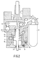
- Figure 2 is a cross-sectional view similar to Figure 1, but wherein a first valve has opened supplying hydraulic pressure to begin moving the actuator toward the right;
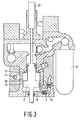
- Figure 3 is a cross-sectional view similar to Figures 1 and 2, but illustrating the actuator piston in a location where its motion is being damped by compressing a predetermined volume of air;
- Figure 4 is a cross-sectional view similar to Figures 1-3, but wherein the actuator piston has reached its rightmost position, its motion arrested, and is being held against the force of the compressed air;
- Figure 5 is a cross-sectional view similar to Figure 4, but with the first valve closed and the actuator awaiting a command to return to its initial position;
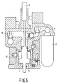
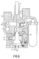
- Figure 6 is a cross-sectional view similar to Figure 5, but wherein a second valve has opened dumping the latching fluid and allowing the actuator piston to be propelled back to its initial position by the compressed air;
- Figure 7 is a view in cross-section showing the actuator of Figures 1-6, returned nearly to the initial position of Figure 1 and emphasizing the adjustable two stage damping to achieve controlled valve seating;
- Figure 8 shows in greater detail the two stage damping arrangement for gentle seating of a poppet valve; and
- Figure 8a is a view in cross-section of the initial damping aperture along lines 8a-8a of Figure 8.
- Corresponding reference characters indicate corresponding parts throughout the several views of the drawing.
- The exemplifications set out herein illustrate a preferred embodiment of the invention in one form thereof and such exemplifications are not to be cnstrued as limiting the scope of the disclosure or the scope of the invention in any manner.
- The present invention utilizes hydraulic fluid to power an actuator from an initial position to a second position. The invention takes advantage of the concepts disclosed in the above-mentioned copending application EP-A-0 468 548 wherein a precise quantity of air is trapped, compressed and stored on the obverse side of the actuator piston as that piston nears its second (valve-open) position. The compressed air and its associated potential energy is stored by locking or capturing the piston shaft by a fluid latch which is made an integral part of the hydraulic system. The actuator may then be commanded to return to the first position by releasing the latching fluid allowing the stored compressed air to return the actuator to the valve-closed position.
- Figure 1 shows the actuator in its first or rest position in which the engine valve is closed. The
shaft 16 connects to a conventional internal combustion engine poppet valve (not shown). Comparing Figures 1 and 2, when aball valve 3 is opened by a solenoid the high pressure hydraulic fluid in theaccumulator 8 quickly forces theball valve 5 open and applies high pressure to thehydraulic subpiston 1. The high pressure causes thesubpiston 1 and itsinterconnected piston 2 to move downwards. This subpiston is formed as the upper portion including the reduced diameter face of thepower piston 2. These twopistons leakproof seals hydraulic chamber 18, acompressed air chamber 15 and a dampingair chamber 17. As the piston assembly is propelled downwards by hydraulic pressure inchamber 18, the air inchamber 15 is being compressed by the lower face ofpiston 2 and will be retained as the primary motive force for the return of the piston assembly to the initial position of Figure 1. During downward motion of the piston assembly, atmospheric pressure air is enteringchamber 17 in an unrestricted manner throughreed valve assembly 14.Chamber 15 is initially charged with low pressure regulated air fromport 10 and one-wayball check valve 9 to maintain a minimal satisfactory latching force onpiston 2. This pneumatic latching force keeps the engine's poppet valve properly seated until commanded to open. - In Figure 3, the actuator piston is continuing its downward travel. In this figure, the
piston seal 19 has just covered the sidewall opening and cut off the latchingair port 10. With the piston positioned as in Figure 3, the air inchamber 15 is being compressed to a very high pressure. This pressure provides a positive damping force to slow the motion of the actuator piston as it approaches its lowest or second position. - Figure 4 illustrates the actuator just after the piston assembly has reached its lowest position. The very high pressure air in
chamber 15 has displaced thepiston 2 back slightly upwards to compress the fluid inchamber 18 to a pressure higher than the system pressure as supplied from theaccumulator 8. Pressure inchamber 18 above the system pressure causes one-way valve 5 to re-close effectively latching the piston assembly and preventing any further rebound toward its initial or first position.Accumulator 8 is also being recharged while the piston assembly rests in the location of Figure 4 by way of hydraulicfluid inlet port 6. - Figure 5 shows the actuator with the piston assembly in its lower stable position. The difference between Figures 4 and 5 is that all valves are now closed and the fluid in
chamber 18 is holding the piston assembly from any motion back upwards due to the very high pressure urging of the air inchamber 15. Also in Figure 5, the replenishing of theaccumulator 8 fluid supply is nearly completed. - In Figure 6, a signal to the
solenoid 25 has openedball valve 4 which dumps the hydraulic fluid fromchamber 18 into lowpressure return port 7. With the high pressure latching pressure removed, the piston assembly is now subjected to a highly unbalanced pressure differential andpiston 2 is now free to respond to the high pressure air inchamber 15 which rapidly accelerates the piston assembly back toward its initial upper position. As the piston assembly moves upwards, it continues to pump hydraulic fluid from thechamber 18past valve 4 and into the lowpressure return port 7. Also as the piston is moving back upwards, the air inchamber 17 is being pumped out through both the initial dampingorifice 12 and the final dampingorifice 11. Each of theseorifices - Figure 7 illustrates the point in the piston assembly return trip where initial damping has been completed and the
piston seal 19 has just closed off the port to orifice 12. Up to this point, damping of upward motion has been determined by the controlled egress of air from thechamber 17 through bothapertures seal 19 has now covered the opening toaperture 12, the damping is increased and fluid now exits more slowly throughaperture 11 only. The size ofaperture 11 controls the final damping to assure gentle seating of the poppet valve as the actuator piston assembly reaches its starting or initial position as illustrated in Figure 1. - Figure 8 illustrates in greater detail the dual stage controlled damping used to control the critical seating of the poppet valve. There is an
air manifold 14 disposed about at least a substantial portion of the periphery of the cylinder which feeds air through amulti-vane reed valve 27. This allows entry of air intochamber 17 during downward movement of the piston assembly in a miner virtually free of any throttling retardation or losses. During return motion of the piston assembly upwards, the reed valve closes and air must escapechamber 17 through theapertures Adjustable needle valves orifices adjustable needle valve 31 and theair escape aperture 12 is illustrated in Figure 8a with theneedle valve 29 and final dampingaperture 11 being structurally similar. Briefly, theaperture 30 extends through the piston wall and communicates withchamber 17 when thepiston 2 is in suitable positions such as shown, for example, in Figure 3. The screw or needle portion ofneedle valve 31 extends orthogonally to this aperture and seats in aconical seat 33. The separation between the end of the needle and the conical seat defines the size of the aperture and may be varied as the screw is moved in or out. Of course, many other types of adjustable apertures may be employed.
Claims (5)
- An asymmetrical bistable hydraulically powered actuator mechanism comprising:- a replenishable source (8) of high pressure hydraulic fluid for causing translation of a portion (1, 2) of the mechanism from an initial position in one direction;- a first damping chamber (15) in which air is compressed during translation of the mechanism portion (1, 2) in said one direction, compression of the air slowing the translation in said one direction of the mechanism portion (1, 2);- means (4, 5, 25) for temporarily preventing reversal of the direction of translation of the mechanism portion (1, 2) when the translation of the mechanism portion (1, 2) slows to a stop;- means (25) operable on command for disabling the temporarily preventing means (4, 5, 25) so as to free the mechanism portion (1, 2) and move the mechanism portion (1, 2) in a direction opposite said one direction under the influence of the pressure of the air compressed in the first damping chamber (15);- and a second damping chamber (17) in which air is compressed during the translation of the mechanism portion (1, 2) in the direction opposite said one direction for damping and slowing the translation of the mechanism portion (1, 2) as it returns to the initial position;
characterized in that the mechanism further comprises a first adjustable aperture (12) allowing air to escape from the second damping chamber (17) during less than the entire travel of the mechanism portion (1, 2) back to the initial position and a second adjustable aperture (11) for allowing air to escape from the second damping chamber (17) during the entire travel of the mechanism portion (1, 2) back to the initial position. - An asymmetrical bistable hydraulically powered actuator mechanism as claimed in Claim 1, characterized in that the mechanism portion (1, 2) includes a reciprocable piston (1, 2) having first, second and third working faces each defining a portion of corresponding first, second and third variable volume chambers (15, 17, 18), the volumes of which vary linearly with the position of the piston (1, 2), said first damping chamber (15) being the first chamber, the second damping chamber (17) being the second chamber, and the third chamber (18) comprising a portion of the means (4, 5, 25) for temporarily preventing reversal of the mechanism portion (1, 2) and cooperating with the replenishable source (8) of high pressure hydraulic fluid for causing translation of the mechanism portion (1, 2).
- An asymmetrical bistable hydraulically powered actuator mechanism as claimed in Claim 2, characterized in that the mechanism further comprises a first selectively actuable high pressure hydraulic fluid inlet valve (3) connecting the third chamber (18) with the source (8) of high pressure hydraulic fluid and a second selectively actuable high pressure hydraulic fluid drain valve (4) connecting the third chamber (18) with a low pressure hydraulic fluid return (7).
- An asymmetrical bistable hydraulically powered actuator mechanism as claimed in Claim 3, characterized in that actuation of the first inlet valve (3) initiates translation of the piston (1, 2) in said one direction, while actuation of the second outlet valve (4) disables the temporarily preventing means (4, 5, 25) and initiates return of the piston (1, 2) to its initial position, the mechanism further including a second inlet valve (9) for supplying a latching air pressure to the first damping chamber (15) at least when the piston (1, 2) is in the initial position to latch the piston (1, 2) in the initial position until the translation of the piston (1, 2) is initiated by the first inlet valve (3).
- An electronically controllable valve mechanism comprising an engine intake or exhaust valve, which is suitable for use in a internal combustion engine and is provided with an elongated valve stem (16), wherein the valve stem (16) is moveable in the direction of stem elongation by an asymmetrical bistable hydraulically powered actuator mechanism as claimed in Claim 1, 2, 3 or 4, characterized in that the valve stem (16) is coupled to the mechanism portion (1, 2) and is moveable in the direction of stem elongation from a valve-closed position, in which the mechanism portion (1, 2) is in the initial position, to a valve-open position, in which the mechanism portion (1, 2) is translated in said one direction under the influence of the high pressure hydraulic fluid.
Applications Claiming Priority (2)
| Application Number | Priority Date | Filing Date | Title |
|---|---|---|---|
| US07/557,369 US5058538A (en) | 1990-07-24 | 1990-07-24 | Hydraulically propelled phneumatically returned valve actuator |
| US557369 | 1990-07-24 |
Publications (2)
| Publication Number | Publication Date |
|---|---|
| EP0468571A1 EP0468571A1 (en) | 1992-01-29 |
| EP0468571B1 true EP0468571B1 (en) | 1995-05-24 |
Family
ID=24225116
Family Applications (1)
| Application Number | Title | Priority Date | Filing Date |
|---|---|---|---|
| EP91201850A Expired - Lifetime EP0468571B1 (en) | 1990-07-24 | 1991-07-15 | Hydraulically propelled pneumatically returned valve actuator |
Country Status (5)
| Country | Link |
|---|---|
| US (1) | US5058538A (en) |
| EP (1) | EP0468571B1 (en) |
| JP (1) | JPH04232319A (en) |
| CA (1) | CA2047448A1 (en) |
| DE (1) | DE69109951T2 (en) |
Families Citing this family (22)
| Publication number | Priority date | Publication date | Assignee | Title |
|---|---|---|---|---|
| US5109812A (en) * | 1991-04-04 | 1992-05-05 | North American Philips Corporation | Pneumatic preloaded actuator |
| US5152260A (en) * | 1991-04-04 | 1992-10-06 | North American Philips Corporation | Highly efficient pneumatically powered hydraulically latched actuator |
| US5255641A (en) | 1991-06-24 | 1993-10-26 | Ford Motor Company | Variable engine valve control system |
| US5193495A (en) * | 1991-07-16 | 1993-03-16 | Southwest Research Institute | Internal combustion engine valve control device |
| DE69211942T2 (en) * | 1991-08-21 | 1996-10-31 | Honda Motor Co Ltd | Lift valve control device for internal combustion engines |
| US5606940A (en) * | 1991-12-31 | 1997-03-04 | Caterpillar Inc. | Engine valve seating velocity hydraulic snubber |
| AU9136491A (en) * | 1991-12-31 | 1993-07-28 | Caterpillar Inc. | Engine valve seating velocity hydraulic snubber |
| US5224683A (en) * | 1992-03-10 | 1993-07-06 | North American Philips Corporation | Hydraulic actuator with hydraulic springs |
| US5253619A (en) * | 1992-12-09 | 1993-10-19 | North American Philips Corporation | Hydraulically powered actuator with pneumatic spring and hydraulic latching |
| US5540201A (en) | 1994-07-29 | 1996-07-30 | Caterpillar Inc. | Engine compression braking apparatus and method |
| US5647318A (en) | 1994-07-29 | 1997-07-15 | Caterpillar Inc. | Engine compression braking apparatus and method |
| US5526784A (en) | 1994-08-04 | 1996-06-18 | Caterpillar Inc. | Simultaneous exhaust valve opening braking system |
| WO1997009516A1 (en) * | 1995-09-01 | 1997-03-13 | Serge Vallve | Pneumatic engine valve assembly |
| DE19544473C2 (en) * | 1995-11-29 | 1999-04-01 | Daimler Benz Ag | Mechanical-hydraulic control for a gas exchange valve of an internal combustion engine |
| US6315265B1 (en) | 1999-04-14 | 2001-11-13 | Wisconsin Alumni Research Foundation | Variable valve timing actuator |
| DE10249452B4 (en) * | 2002-10-24 | 2009-10-15 | Man Diesel, Filial Af Man Diesel Se, Tyskland | outlet valve |
| DE102006040671A1 (en) * | 2006-08-30 | 2008-03-06 | Schaeffler Kg | Throttle valve for an internal combustion engine with electrohydraulic valve control |
| US7603858B2 (en) * | 2007-05-11 | 2009-10-20 | Lawrence Livermore National Security, Llc | Harmonic engine |
| US8051811B2 (en) * | 2007-08-07 | 2011-11-08 | Scuderi Group, Llc | Knock resistant split-cycle engine |
| DE102008054014A1 (en) * | 2008-10-30 | 2010-05-06 | Man Nutzfahrzeuge Aktiengesellschaft | Gas exchange valve for internal combustion engines |
| US9291056B2 (en) | 2010-08-30 | 2016-03-22 | Lawrence Livermore National Security, Llc | Harmonic uniflow engine |
| US8807012B1 (en) | 2010-08-30 | 2014-08-19 | Lawrence Livermore National Security, Llc | Harmonic engine |
Family Cites Families (15)
| Publication number | Priority date | Publication date | Assignee | Title |
|---|---|---|---|---|
| US3537355A (en) * | 1966-12-14 | 1970-11-03 | George N Bliss | Fluid-operated servomechanism |
| US4206728A (en) * | 1978-05-01 | 1980-06-10 | General Motors Corporation | Hydraulic valve actuator system |
| US4759260A (en) * | 1978-05-17 | 1988-07-26 | Lew Yon S | Super reliable air-spring return air cylinder |
| DK225982A (en) * | 1981-07-07 | 1983-01-08 | Sulzer Ag | INHIBIT OR EXHAUST VALVE TO A CYLINDER TOP OF A COMBUSTION ENGINE |
| DE3139399A1 (en) * | 1981-09-30 | 1983-04-14 | Gebrüder Sulzer AG, 8401 Winterthur | Drive for a system which is capable of oscillation |
| SU1132034A1 (en) * | 1983-02-23 | 1984-12-30 | Ворошиловградский машиностроительный институт | Device for distributing valve hydraulic actuator |
| US4555974A (en) * | 1983-09-02 | 1985-12-03 | Pneumo Corporation | Servo actuator control/damping mechanism and method |
| DK149514C (en) * | 1983-09-16 | 1986-12-22 | Danfoss As | HYDRAULIC ACTUATOR FOR VALVE MANAGEMENT |
| SE459516B (en) * | 1984-02-09 | 1989-07-10 | Bo Inge Gustav Jareke | PNEUMATIC SERVICE VALVE INCLUDING ONE IN A CYLINDER ROLLABLE DOUBLE PISTON |
| US4777800A (en) * | 1984-03-05 | 1988-10-18 | Vetco Gray Inc. | Static head charged hydraulic accumulator |
| US4889035A (en) * | 1985-07-16 | 1989-12-26 | Thermo Electron Web Systems, Inc. | Magnetically actuated valve for cyclically operating piston-cylinder actuator |
| US4836757A (en) * | 1987-02-13 | 1989-06-06 | Mechanical Technology Incorporated | Pressure actuated movable head for a resonant reciprocating compressor balance chamber |
| JPH0794845B2 (en) * | 1987-02-24 | 1995-10-11 | 本田技研工業株式会社 | Differential pressure actuator |
| US4922805A (en) * | 1988-09-14 | 1990-05-08 | Beswick Paul R | Fluid actuated cylinder |
| JP2664986B2 (en) * | 1989-04-03 | 1997-10-22 | 三菱重工業株式会社 | Valve train for internal combustion engine |
-
1990
- 1990-07-24 US US07/557,369 patent/US5058538A/en not_active Expired - Lifetime
-
1991
- 1991-07-15 DE DE69109951T patent/DE69109951T2/en not_active Expired - Fee Related
- 1991-07-15 EP EP91201850A patent/EP0468571B1/en not_active Expired - Lifetime
- 1991-07-19 CA CA002047448A patent/CA2047448A1/en not_active Abandoned
- 1991-07-24 JP JP3206206A patent/JPH04232319A/en active Pending
Also Published As
| Publication number | Publication date |
|---|---|
| CA2047448A1 (en) | 1992-01-25 |
| EP0468571A1 (en) | 1992-01-29 |
| DE69109951D1 (en) | 1995-06-29 |
| US5058538A (en) | 1991-10-22 |
| JPH04232319A (en) | 1992-08-20 |
| DE69109951T2 (en) | 1995-12-21 |
Similar Documents
| Publication | Publication Date | Title |
|---|---|---|
| EP0468571B1 (en) | Hydraulically propelled pneumatically returned valve actuator | |
| US5152260A (en) | Highly efficient pneumatically powered hydraulically latched actuator | |
| US4883025A (en) | Potential-magnetic energy driven valve mechanism | |
| US4831973A (en) | Repulsion actuated potential energy driven valve mechanism | |
| US5022358A (en) | Low energy hydraulic actuator | |
| US4878464A (en) | Pneumatic bistable electronic valve actuator | |
| US4974495A (en) | Electro-hydraulic valve actuator | |
| US4852528A (en) | Pneumatic actuator with permanent magnet control valve latching | |
| US4000756A (en) | High speed engine valve actuator | |
| EP0468548B1 (en) | Actuator with energy recovery return | |
| US5221072A (en) | Resilient hydraulic actuator | |
| JP2645942B2 (en) | Method and apparatus for controlling supply and exhaust valves of an internal combustion engine | |
| US5125371A (en) | Spring driven hydraulic actuator | |
| US4967702A (en) | Fast acting valve | |
| US4915015A (en) | Pneumatic actuator | |
| US4899700A (en) | Pneumatically powered valve actuator | |
| US5109812A (en) | Pneumatic preloaded actuator | |
| US4942852A (en) | Electro-pneumatic actuator | |
| US5003938A (en) | Pneumatically powered valve actuator | |
| US4991548A (en) | Compact valve actuator | |
| WO1993001399A1 (en) | Recuperative engine valve system and method of operation | |
| EP1199446B1 (en) | Method and arrangement for operating valves in an internal combustion engine | |
| JP2022511027A (en) | Methods and devices for electrically controlling valve actuators in internal combustion engines |
Legal Events
| Date | Code | Title | Description |
|---|---|---|---|
| PUAI | Public reference made under article 153(3) epc to a published international application that has entered the european phase |
Free format text: ORIGINAL CODE: 0009012 |
|
| AK | Designated contracting states |
Kind code of ref document: A1 Designated state(s): DE FR GB IT SE |
|
| 17P | Request for examination filed |
Effective date: 19920724 |
|
| 17Q | First examination report despatched |
Effective date: 19930329 |
|
| GRAA | (expected) grant |
Free format text: ORIGINAL CODE: 0009210 |
|
| AK | Designated contracting states |
Kind code of ref document: B1 Designated state(s): DE FR GB IT SE |
|
| REF | Corresponds to: |
Ref document number: 69109951 Country of ref document: DE Date of ref document: 19950629 |
|
| ITF | It: translation for a ep patent filed |
Owner name: ING. C. GREGORJ S.P.A. |
|
| ET | Fr: translation filed | ||
| PLBE | No opposition filed within time limit |
Free format text: ORIGINAL CODE: 0009261 |
|
| STAA | Information on the status of an ep patent application or granted ep patent |
Free format text: STATUS: NO OPPOSITION FILED WITHIN TIME LIMIT |
|
| 26N | No opposition filed | ||
| REG | Reference to a national code |
Ref country code: GB Ref legal event code: 732E |
|
| REG | Reference to a national code |
Ref country code: FR Ref legal event code: TP |
|
| REG | Reference to a national code |
Ref country code: GB Ref legal event code: IF02 |
|
| PGFP | Annual fee paid to national office [announced via postgrant information from national office to epo] |
Ref country code: GB Payment date: 20020711 Year of fee payment: 12 |
|
| PGFP | Annual fee paid to national office [announced via postgrant information from national office to epo] |
Ref country code: SE Payment date: 20020724 Year of fee payment: 12 |
|
| PGFP | Annual fee paid to national office [announced via postgrant information from national office to epo] |
Ref country code: FR Payment date: 20020726 Year of fee payment: 12 |
|
| PGFP | Annual fee paid to national office [announced via postgrant information from national office to epo] |
Ref country code: DE Payment date: 20020916 Year of fee payment: 12 |
|
| PG25 | Lapsed in a contracting state [announced via postgrant information from national office to epo] |
Ref country code: GB Free format text: LAPSE BECAUSE OF NON-PAYMENT OF DUE FEES Effective date: 20030715 |
|
| PG25 | Lapsed in a contracting state [announced via postgrant information from national office to epo] |
Ref country code: SE Free format text: LAPSE BECAUSE OF NON-PAYMENT OF DUE FEES Effective date: 20030716 |
|
| PG25 | Lapsed in a contracting state [announced via postgrant information from national office to epo] |
Ref country code: DE Free format text: LAPSE BECAUSE OF NON-PAYMENT OF DUE FEES Effective date: 20040203 |
|
| EUG | Se: european patent has lapsed | ||
| GBPC | Gb: european patent ceased through non-payment of renewal fee |
Effective date: 20030715 |
|
| PG25 | Lapsed in a contracting state [announced via postgrant information from national office to epo] |
Ref country code: FR Free format text: LAPSE BECAUSE OF NON-PAYMENT OF DUE FEES Effective date: 20040331 |
|
| REG | Reference to a national code |
Ref country code: FR Ref legal event code: ST |
|
| PG25 | Lapsed in a contracting state [announced via postgrant information from national office to epo] |
Ref country code: IT Free format text: LAPSE BECAUSE OF NON-PAYMENT OF DUE FEES Effective date: 20050715 |