EP0468030B1 - Gasprobenahmevorrichtung mit verbessertem axial-radial-ventilator - Google Patents
Gasprobenahmevorrichtung mit verbessertem axial-radial-ventilator Download PDFInfo
- Publication number
- EP0468030B1 EP0468030B1 EP91904258A EP91904258A EP0468030B1 EP 0468030 B1 EP0468030 B1 EP 0468030B1 EP 91904258 A EP91904258 A EP 91904258A EP 91904258 A EP91904258 A EP 91904258A EP 0468030 B1 EP0468030 B1 EP 0468030B1
- Authority
- EP
- European Patent Office
- Prior art keywords
- fan
- gas
- sampling device
- housing
- chamber
- Prior art date
- Legal status (The legal status is an assumption and is not a legal conclusion. Google has not performed a legal analysis and makes no representation as to the accuracy of the status listed.)
- Expired - Lifetime
Links
- 238000005070 sampling Methods 0.000 title claims abstract description 59
- 239000012530 fluid Substances 0.000 claims abstract description 6
- 239000000523 sample Substances 0.000 claims description 24
- 230000002093 peripheral effect Effects 0.000 claims description 8
- 230000003197 catalytic effect Effects 0.000 claims description 3
- 239000007787 solid Substances 0.000 claims description 3
- 230000007704 transition Effects 0.000 claims description 3
- 239000007789 gas Substances 0.000 description 134
- 210000002445 nipple Anatomy 0.000 description 15
- UGFAIRIUMAVXCW-UHFFFAOYSA-N Carbon monoxide Chemical compound [O+]#[C-] UGFAIRIUMAVXCW-UHFFFAOYSA-N 0.000 description 6
- 239000003546 flue gas Substances 0.000 description 5
- 241000555745 Sciuridae Species 0.000 description 3
- 239000012528 membrane Substances 0.000 description 3
- RAHZWNYVWXNFOC-UHFFFAOYSA-N Sulphur dioxide Chemical compound O=S=O RAHZWNYVWXNFOC-UHFFFAOYSA-N 0.000 description 2
- 239000004973 liquid crystal related substance Substances 0.000 description 2
- 230000010349 pulsation Effects 0.000 description 2
- XLYOFNOQVPJJNP-UHFFFAOYSA-N water Substances O XLYOFNOQVPJJNP-UHFFFAOYSA-N 0.000 description 2
- 230000002411 adverse Effects 0.000 description 1
- QVGXLLKOCUKJST-UHFFFAOYSA-N atomic oxygen Chemical compound [O] QVGXLLKOCUKJST-UHFFFAOYSA-N 0.000 description 1
- 229910002091 carbon monoxide Inorganic materials 0.000 description 1
- 239000000356 contaminant Substances 0.000 description 1
- 230000001419 dependent effect Effects 0.000 description 1
- 238000001514 detection method Methods 0.000 description 1
- 230000003670 easy-to-clean Effects 0.000 description 1
- 239000007788 liquid Substances 0.000 description 1
- 238000012423 maintenance Methods 0.000 description 1
- 238000004519 manufacturing process Methods 0.000 description 1
- 229910052760 oxygen Inorganic materials 0.000 description 1
- 239000001301 oxygen Substances 0.000 description 1
Images


Classifications
-
- G—PHYSICS
- G01—MEASURING; TESTING
- G01N—INVESTIGATING OR ANALYSING MATERIALS BY DETERMINING THEIR CHEMICAL OR PHYSICAL PROPERTIES
- G01N33/00—Investigating or analysing materials by specific methods not covered by groups G01N1/00 - G01N31/00
- G01N33/0004—Gaseous mixtures, e.g. polluted air
- G01N33/0009—General constructional details of gas analysers, e.g. portable test equipment
-
- F—MECHANICAL ENGINEERING; LIGHTING; HEATING; WEAPONS; BLASTING
- F04—POSITIVE - DISPLACEMENT MACHINES FOR LIQUIDS; PUMPS FOR LIQUIDS OR ELASTIC FLUIDS
- F04D—NON-POSITIVE-DISPLACEMENT PUMPS
- F04D17/00—Radial-flow pumps, e.g. centrifugal pumps; Helico-centrifugal pumps
- F04D17/08—Centrifugal pumps
- F04D17/16—Centrifugal pumps for displacing without appreciable compression
-
- G—PHYSICS
- G01—MEASURING; TESTING
- G01N—INVESTIGATING OR ANALYSING MATERIALS BY DETERMINING THEIR CHEMICAL OR PHYSICAL PROPERTIES
- G01N1/00—Sampling; Preparing specimens for investigation
- G01N1/02—Devices for withdrawing samples
- G01N1/22—Devices for withdrawing samples in the gaseous state
- G01N1/2273—Atmospheric sampling
-
- G—PHYSICS
- G01—MEASURING; TESTING
- G01N—INVESTIGATING OR ANALYSING MATERIALS BY DETERMINING THEIR CHEMICAL OR PHYSICAL PROPERTIES
- G01N1/00—Sampling; Preparing specimens for investigation
- G01N1/02—Devices for withdrawing samples
- G01N1/22—Devices for withdrawing samples in the gaseous state
- G01N1/24—Suction devices
-
- G—PHYSICS
- G01—MEASURING; TESTING
- G01N—INVESTIGATING OR ANALYSING MATERIALS BY DETERMINING THEIR CHEMICAL OR PHYSICAL PROPERTIES
- G01N1/00—Sampling; Preparing specimens for investigation
- G01N1/02—Devices for withdrawing samples
- G01N1/22—Devices for withdrawing samples in the gaseous state
- G01N1/2273—Atmospheric sampling
- G01N2001/2276—Personal monitors
-
- G—PHYSICS
- G01—MEASURING; TESTING
- G01N—INVESTIGATING OR ANALYSING MATERIALS BY DETERMINING THEIR CHEMICAL OR PHYSICAL PROPERTIES
- G01N1/00—Sampling; Preparing specimens for investigation
- G01N1/02—Devices for withdrawing samples
- G01N1/22—Devices for withdrawing samples in the gaseous state
- G01N1/24—Suction devices
- G01N2001/245—Fans
Definitions
- the invention relates to the detection of gases and, more particularly, to gas sampling devices including a gas sensor and a circular fan driven by a motor, which draw a sample gas to a sensor within the device.
- Gas sampling devices for sampling a gas and determining the concentration of a particular gas in the sample gas are well-known.
- gas sampling devices generally include a gas sensor, which develops an electrical signal in response to the presence of a particular gas, and circuitry for converting that signal into an output reading.
- Gas sampling devices often include a pump which draws the sample gas through a probe and causes the gas to pass over the sensor.
- Hand-held, battery operated gas sampling devices are also well-known. These devices are used to test for the presence of a particular gas in remote areas or other locations where it is impractical to use larger, bench devices. Hand-held gas sampling devices are commonly used by inspectors to check the operation of furnaces, gas hot water heaters and devices in which excess concentrations of carbon monoxide, sulfur dioxide, oxygen or the like is an indication of a problem.
- reciprocating pumps have a number of drawbacks. Specifically, the gas flowing from a reciprocating pump exhibits pressure pulsations resulting from the reciprocation of a diaphragm internal to the pump. Such pressure pulsations interfere with the operation of many gas sensors, such as electrochemical gas sensors which are extremely pressure sensitive. Moreover, a reciprocating pump requires an expensive and powerful motor and is sensitive to dirt and liquid.
- a squirrel cage type of centrifugal fan has also been used to draw a sample gas into a gas sampling device.
- a fan develops only a low pressure potential and cannot draw a sample gas against a large pressure.
- the structure permits residual gas to remain after a test, which could adversely affect the reading obtained from a subsequent test.
- the squirrel cage fan draws far too much gas volume and uses too much energy from the power source for the device.
- a gas sampling device which includes a chamber including a chamber top mounted to a chamber base.
- the chamber base has a gas flow passage extending therethrough and into the chamber.
- a circular fan is positioned with the chamber and is spaced from and directs gas flows toward the gas flow passage.
- the fan is rotatable in a plane substantially parallel to an upper surface of the chamber base.
- a motor is mounted to a lower surface of the chamber base and has a shaft extending perpendicularly through the chamber base and attached to the fan.
- a gas sensor is mounted to the lower surface of the chamber base and is in fluid communication with the gas flow passage.
- An inlet flow passage extends through the chamber top above the fan and is oriented substantially perpendicular thereto.
- an outlet flow passage extends through the chamber top above the gas flow passage
- the chamber top includes a fan housing surrounding but spaced from an outer perimeter of the fan.
- the chamber top also includes a gas tunnel housing extending tangentially from the fan housing to the gas flow passage.
- the fan housing has an inner wall which has a linearly increasing, outward spiral shape in which the spacing between the outer perimeter of the fan and the inner wall gradually increases, in the direction of rotation of the fan, from a minimum in an area following the gas tunnel housing, to a maximum in a transition area between the fan housing and the outer wall of the gas tunnel housing.
- the spacing between the side of the fan and the inner wall of the fan housing is about 6-12%, preferably 8%, of the outer diameter of the fan in the area immediately following the gas tunnel housing.
- the spacing between an inner upper surface of the fan housing and a top edge of the fan blades is about 6-12%, preferably 8%, of the outer diameter of the fan.
- the fan includes a circular bottom member having a flat central area and a tapered peripheral area extending from the central area toward the chamber base.
- the fan also includes a plurality of spaced fan blades, alternating between long fan blades and short fan blades, which extend substantially vertically along an upper surface of the bottom member.
- the fan blades also extend radially along the tapered peripheral area and into the flat central area.
- the fan blades have tips which are spaced from a center of the fan, with the long fan blades extending further toward the center of the fan than the short fan blades.
- the fan can also include along its outer perimeter a thin skirt extending toward but spaced from the chamber base. It is also preferred that the space between the tips of adjacent long fan blades be about the same as the space between the tips of adjacent long and short fan blades.
- the motor used to power the fan be a direct current motor capable of rotating at least 7,000 rpm.
- the gas sensor can be any of the known types of gas sensors, including electrochemical, catalytic combustible, solid state and electro-optic gas sensors.
- the gas sampling device can be advantageously used with a variety of probes. It is particularly advantageous with a probe which includes both an inlet passageway for supplying gas to the inlet flow passage of the device and also an outlet passageway for exhausting gas from the outlet flow passage of the device back to the atmosphere or to the source of the sample gas.
- FIGS. 1-3 A portable, battery operated gas sampling device 2 in accordance with the present invention is shown in FIGS. 1-3.
- the gas sampling device 2 includes a front housing 4 connected to a rear housing 6.
- the housings 4, 6 contain the working elements of the gas sampling device 2.
- the rear housing 6 includes a battery compartment therein which is sealed by a removable battery compartment cover 8.
- the front and rear housings 4, 6 are shown having a wide upper portion and narrow lower portion, but other shapes and configurations can be readily used.
- the lower portions of the front and rear housings 4, 6 can include grip areas 10 to provide for ease in handling the gas sampling device 2.
- the rear housing 6 has an elastic strap 12 extending from an upper portion thereof to a lower portion of the battery compartment cover 8.
- the strap 12 can be removably secured to the battery compartment cover 8 by a clip 14 or the like.
- the strap 12 will snugly, yet comfortably, hold a user's hand in place around the grip areas 10 of the gas sampling device 2 and keep the device 2 from being accidentally dropped.
- the upper portion of the gas sampling device 2 includes through the rear housing 6 an inlet nipple 16 for directing the inlet flow of a sample gas under test, and an outlet nipple 18 for directing the sample gas either back to its original source or to atmosphere.
- the gas sampling device 2 develops a signal indicative of the concentration of a particular gas and the concentration is shown on a liquid crystal display 20 or other known display or read out means.
- the front housing 4 can also include convenient control buttons. As shown, the front housing 4 includes a power switch 22, a light switch 24 for the display 20, and a potentiometer 26.
- the potentiometer 26 is a well-known element in gas sampling devices and is used to calibrate the device before a sample gas is passed therethrough.
- the device 2 includes a printed circuit board 28 supported by a plurality of bosses 30 formed integrally with the front housing 4. Similar bosses are formed in the rear housing 6 and will snugly support the printed circuit board 28 within the gas sampling device 2.
- a lower end of the printed circuit board 28 includes a pair of battery contacts 32. Opposing battery contacts can be provided either on an upper end of the printed circuit board 28 or on the rear housing 6.
- the gas sampling device 2 also includes a motor 34 which is electrically connected to the printed circuit board 28 by a pair of motor wires 36.
- the motor 34 is preferably a small DC motor capable of rotating at speeds of 7,000 rpm or higher.
- the gas sampling device 2 also includes a gas sensor 38 which is electrically connected to the printed circuit board 28 by a plurality of sensor wires 40.
- the sensor 38 can be a three electrode electrochemical gas sensor which includes reference, sensing and cathode electrodes. Each of these electrodes requires a separate wire to the printed circuit board 28.
- FIG. 4 shows three sensor wires 40 extending from the sensor 38 to the printed circuit board 28.
- the sensor 38 can also be a catalytic combustible gas sensor, a solid state gas sensor or an electro-optic gas sensor.
- a gas chamber formed of a substantially planar chamber base 42 and a chamber top 44 is provided within the gas sampling device 2 above the motor 34 and the sensor 38 and beneath the top of the gas sampling device 2.
- a circular fan 46 is positioned in the gas chamber formed by the chamber top 44 and chamber base 42, and rotates in a plane substantially parallel to an upper surface of the chamber base 42.
- the motor 34 is mounted on a lower surface of the chamber base 42 and is connected to the fan 46 by a motor shaft 48 which extends perpendicularly through the chamber base 42.
- a gas flow passage or hole 50 extends through the chamber base 42 immediately above and in fluid communication with the gas sensor 38 which is mounted on the lower surface of the chamber base 42.
- the chamber top 44 includes a bottom flange 52 and a raised housing 54.
- the inlet nipple 16 is connected to the raised housing 54 and has a flow passage extending therethrough to the interior of the raised housing 54.
- the inlet nipple 16 forms an inlet flow passage through the chamber top 54 and is positioned immediately above the center of the fan 46 and is oriented substantially perpendicular thereto.
- the outlet nipple 18 is also connected to the raised housing 54 and has a flow passage extending therethrough to the interior of the raised housing 54.
- the outlet nipple 18 provides an outlet flow passage extending through the chamber top 54 and is positioned above the gas flow passage 50.
- the fan 46 is mounted above the upper surface of the chamber base 42 and is spaced apart from the gas flow passage 50.
- the chamber base 42 is essentially a rectangular plate with rounded corners.
- the flange 52 of the chamber top 44 extends outwardly by a particular amount and to a particular configuration such that the chamber top 44 has an outer shape matching that of the chamber base 42. In this manner, the chamber top 44 can be securely mounted, for example with fasteners, to the chamber base 42 to form the chamber assembly.
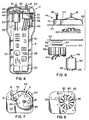
- the chamber assembly 42, 44, the fan 46, the motor 34, and the gas sensor 38 are shown more clearly in FIG. 6.
- the lower surface of the chamber base 42 includes cylindrical ridge 58 surrounding the gas flow passage 50.
- This cylindrical ridge 58 holds a thin, circular membrane 60 which is positioned above the inlet to the gas sensor 38.
- An O-ring 62 is positioned between the circular membrane 60 and the gas sensor 38, and the gas sensor 38 is secured to the chamber assembly 42, 44 by bolts or the like.
- the circular membrane 60 is a known device for controlling the flow of gas to the gas sensor 38.
- the fan 46 is positioned above the upper surface of the chamber base 42, and the shaft 48 of the motor 34 passes through the chamber base 42 and is connected to the fan 46.
- a cushioning gasket 64 can be positioned between the motor 34 and the lower surface of the chamber base 42 to reduce vibration and provide for a secure fit.
- the motor is secured to the chamber base 42 by suitable fasteners.
- the motor 34 shown in FIG. 6 includes a pair of motor wire contacts 66 to which are connected the motor wires 36 shown in FIG. 4.
- the chamber top 44 is secured to the chamber base 42 by suitable fasteners.
- the raised housing 54 in the chamber top 44 includes a raised fan housing 68 which surrounds but is spaced from the fan 46.
- the raised housing 54 also includes a gas tunnel housing 70 integral therewith which extends tangentially from the fan housing 68 to the gas flow passage 50 when the chamber top 44 is mounted to the chamber base 42.
- the inlet nipple 16 is positioned in approximately the center of the fan housing 68 and is oriented to direct gas flows perpendicular therethrough to the center of the fan 46.
- the outlet nipple 18 is positioned in the gas tunnel housing 70 above the gas flow passage 50.
- the fan housing 68 of the raised housing 54 includes a particular spacing between the outer perimeter of the fan 46 and the inner wall 84 of the fan housing 68.
- the fan housing 68 includes an inner wall 84 which has a linearly increasing, outward spiral shape, also called an involute spiral shape, in which the spacing between the outer perimeter of the fan 46 and the inner wall 84 gradually increases, in the direction of rotation of the fan 46, from a minimum in the area following the gas tunnel housing 70 to a maximum at a transition area between the fan housing 68 and the gas tunnel housing 70. This is shown more clearly in both FIGS. 7 and 9, with the approximate locations of the minimum and maximum spacings shown by reference letters A and B, respectively.
- the spacing between the outer perimeter of the fan 46 and the inner wall 84 of the fan housing 68 should be about 6 to 12% of the outer diameter of the fan 46 at the minimum spacing. It is preferred that the spacing be about 8% of the outer diameter of the fan 46 at this location. In addition, it is preferred that the spacing between an inner upper surface 86 of the fan housing 68 and a top edge of the fan 46 be about 6 to 12%, preferably about 8%, of the outer diameter of the fan 46.
- the fan 46 is shown in detail in FIGS. 8-11.
- the fan 46 can be referred to as a mixed flow fan because, as will be explained hereinafter in more detail, the flows through the fan 46 are in both radial and axial directions.
- the fan 46 includes a circular bottom member having a flat central area 72 and a tapered peripheral area 74 extending outwardly from the central area 72 toward the chamber base 42 when the fan 46 is assembled on the motor shaft 48.
- the peripheral edge of the fan 46 can also include a downwardly oriented skirt 76 around its circumference.
- the bottom surface of the central area 72 of the fan 46 includes a mounting collar 78 which is adapted to securely receive the shaft 48 of the motor 34.
- the mounting collar 78 preferably does not extend downwardly below the bottom edge of the skirt 76 of the fan 46.
- the fan 46 also includes a plurality of spaced fan blades, alternating between long fan blades 80 and short fan blades 82, which are oriented substantially vertical to the upper surface of the bottom member of the fan 46 and extend generally radially therealong. As shown more clearly in FIG. 10, the fan blades 80, 82 extend from the peripheral edge of the fan 46 toward the center of the fan 46 along the tapered peripheral area 74 and into the flat central area 72. However, the tips of the fan blades 80, 82 are spaced from the center of the fan 46 to provide an area in the middle of the flat central area 72 which has no fan blades. The long fan blades 80 extend further toward the center of the fan 46 than the short blades 82.
- the spacing between the tips of adjacent long fan blades 80 be approximately the same as the spacing between the tips of an adjacent long fan blade 80 and short fan blade 82.
- the particular arrangement of the fan blades 80, 82, with the staggered arrangement in the center of the fan 46, provides for smooth gas flow through the fan 46 at a proper pressure and with no choking of the gas flow.
- the motor 34 rotates the fan 46 within the fan housing 68 and creates a vacuum which draws gas axially through the inlet nipple 16 and into the central area 72 of the fan 46.
- the gas then flows radially along the fan blades 80, 82 toward the inner wall 84 of the fan housing 68 and then flows along the inner wall 84 generally tangential to the skirt 76 of the fan 46.
- the gas then flows into the gas tunnel housing 70 where it passes into the gas flow passage 50 in the chamber base 42 and comes in contact with the gas sensor 38 located therebeneath.
- the gas sensor 38 detects the concentration of a particular gas, if present, and develops a signal supplied to the printed circuit board 28.
- the circuitry on the printed circuit board 28 converts this signal into a reading on the liquid crystal display 20.
- the tested gas then passes out of the gas tunnel housing 70 through the outlet nipple 18. It is preferred that the power to the motor 34 be supplied through a voltage regulator on the printed circuit board 28, rather than directly from the batteries, to prevent variations in fan speed due to a decrease in battery strength. This will keep pressure variation on the gas sensor 38 to a minimum.
- FIG. 12 A system for sampling a flue gas, using the gas sampling device 2 discussed above, is shown in FIG. 12.
- a probe 90 is inserted through the side of a flue 92 which has flue gas flowing therethrough.
- the probe 90 is constructed of an inner cylindrical tube 94 which is surrounded by a concentric outer tube 96 spaced therefrom. The spacing between the outer surface of the inner tube 94 and the inner surface of the outer tube 96 provides an annular chamber therebetween.
- a first end 98 of the outer tube 96 located within the flue 92 is closed off and the inner tube 94 extends therethrough for a short distance into the flue 92.
- a second end 100 of the outer tube 98 is closed off and the inner tube 94 extends outwardly therethrough for a short distance.
- An inlet hose 102 extends from the inlet nipple 16 of the gas sampling device 2 and is connected to the inner tube 94 at the second end 100 of the outer tube 96 of the probe 90.
- an outlet hose 104 is connected from the outlet nipple 18 of the gas sampling device 2 and is connected to an outlet fitting 106 on the probe 90 near the second end 100.
- the outlet fitting 106 is in fluid communication with the annular chamber between the outer tube 96 and the inner tube 94.
- the outer tube 96 also includes a plurality of exhaust openings 108 therethrough adjacent the first end 98 and in fluid communication with the annular chamber between the inner tube 94 and the outer tube 96.
- the sample gas can be drawn from the flue 92 through the inner tube 94, through the inlet hose 102 and into the gas sampling device 2 through the inlet nipple 16.
- the tested gas will then pass from the gas sampling device 2 through the outlet nipple 18 and outlet hose 104, through the outlet fitting 106 and into the annular chamber between the inner tube 94 and the outer tube 96.
- the gas will then flow between the inner tube 94 and outer tube 96 to the exhaust openings 108 in the outer tube 96, where the gas will pass into the flue 92 and be exhausted along with the unsampled flue gas.
- the gas sampling device 2 need only provide a differential pressure to overcome the net pressure loss in the flow path from the end of the inner tube 94 in the flue 92 and back to the exhaust openings 108 in the probe 90.
- the gas sampling device 2 need not provide the large pressure necessary to overcome the large, negative pressure often found in a flue gas.
- the gas sampling device 2 can also be used with standard probes and the use of an exhaust path from the outlet nipple 18 need not always be provided.
- the gas sampling device of the present invention provides an arrangement which is relatively inexpensive to manufacture and has low power consumption, permitting a less powerful and inexpensive motor to be used and giving the batteries a longer operating life.
- the smooth flow of gas through the chamber eliminates pressure variations to the sensor. Only an amount of gas sufficient to conduct the test is drawn into the device.
- the structure permits little residual gas in the device, it is relatively insensitive to contaminants and it is easy to clean and maintain.
Landscapes
- Engineering & Computer Science (AREA)
- Health & Medical Sciences (AREA)
- Life Sciences & Earth Sciences (AREA)
- Chemical & Material Sciences (AREA)
- Biochemistry (AREA)
- General Health & Medical Sciences (AREA)
- General Physics & Mathematics (AREA)
- Physics & Mathematics (AREA)
- Immunology (AREA)
- Analytical Chemistry (AREA)
- Pathology (AREA)
- Biomedical Technology (AREA)
- Molecular Biology (AREA)
- General Engineering & Computer Science (AREA)
- Mechanical Engineering (AREA)
- Combustion & Propulsion (AREA)
- Food Science & Technology (AREA)
- Medicinal Chemistry (AREA)
- Sampling And Sample Adjustment (AREA)
Claims (13)
- Gasprobenentnahmevorrichtung (2), miteinem Gassensor (38),einer Kammer, die ein Kammeroberteil (44) aufweist, welches an einem Kammerbasisteil (42) befestigt ist,einem kreisförmigen Lüfter (46), der durch einen Motor (34) angetrieben wird, wobei der kreisförmige Lüfter (46) innerhalb der Kammer angeordnet ist und der Lüfter (46) in einer Ebene in etwa parallel zu einer oberen Fläche des Kammerbasisteils (42) drehbar ist;einer Einlaßdurchflußöffnung (16), die sich durch das Kammeroberteil (44) über dem Lüfter (46) erstreckt und in etwa senkrecht dazu ausgerichtet ist; undeiner Auslaßdurchflußöffnung (18),wobei die Vorrichtung (2) dadurch gekennzeichnet ist, daßdas Kammerbasisteil (42) eine Gasdurchflußöffnung (50) hat, die sich durch dieses in die Kammer erstreckt;der Lüfter von der Gasdurchflußöffnung (50) beabstandet ist und Gasströme in Richtung auf diese lenkt,der Motor (34) an der unteren Fläche des Kammerbasisteils (42) befestigt ist und eine Welle (48) hat, die sich senkrecht durch das Kammerbasisteil (42) erstreckt und am Lüfter (46) befestigt ist;der Gassensor (38) an der unteren Fläche des Kammerbasisteils (42) befestigt ist und in Fluid-Verbindung mit der Gasdurchflußöffnung (50) ist;und die Auslaßdurchflußöffnung (18) sich durch das Kammeroberteil (44) über der Gasdurchflußöffnung (50) erstreckt, wobei das Kammeroberteil (44) ein Lüftergehäuse (68) besitzt, welches eine äußere Begrenzung des Lüfters (46) umgibt, jedoch davon beabstandet ist, und ein Gastunnelgehäuse (70), welches sich tangential vom Lüftergehäuse (68) zur Gasdurchflußöffnung (50) erstreckt, wobei das Lüftergehäuse (68) eine Innenwand (84) hat, welche eine linear sich vergrößernde, äußere spiralförmige Form besitzt, in welcher der Zwischenraum zwischen der äußeren Begrenzung des Lüfters (46) und der Innenwand (84) in der Drehrichtung des Lüfters (46) von einem Minimum in einem Bereich, der auf das Gastunnelgehäuse (70) folgt, zu einem Maximum in einem Übergangsbereich zwischen dem Lüftergehäuse (68) und der Außenwand des Gastunnelgehäuses (70) allmählich zunimmt.
- Gasprobenentnahmevorrichtung nach Anspruch 1, wobei der Zwischenraum zwischen der äußeren Begrenzung des Lüfters (46) und der Innenwand (84) des Lüftergehäuses (68) ungefähr 6 bis 12% des Außendurchmessers des Lüfters (46) in dem Bereich beträgt, der auf das Gastunnelgehäuse (70) folgt.
- Gasprobenentnahmevorrichtung nach Anspruch 1, wobei der Zwischenraum zwischen der äußeren Begrenzung des Lüfters (46) und der Innenwand des Lüftergehäuses (68) ungefähr 8% des Außendurchmessers des Lüfters (46) in dem Bereich beträgt, der auf das Gastunnelgehäuse (70) folgt.
- Gasprobenentnahmevorrichtung nach Anspruch 1, wobei der Zwischenraum zwischen einer inneren oberen Fläche (86) des Lüftergehäuses (68) und einem Kopfrand des Lüfters (46) ungefähr 6 bis 12% des Außendurchmessers des Lüfters (46) beträgt.
- Gasprobenentnahmevorrichtung nach Anspruch 1, wobei der Zwischenraum zwischen einer inneren oberen Fläche (86) des Lüftergehäuses (68) und einem Kopfrand des Lüfters (46) ungefähr 8% des Außendurchmessers des Lüfters (46) beträgt.
- Gasprobenentnahmevorrichtung nach Anspruch 1, wobei der Zwischenraum zwischen der äußeren Begrenzung des Lüfters (46) und der Innenwand (84) des Lüftergehäuses (68) ungefähr 6 bis 12% des Außendurchmessers des Lüfters (46) in dem Bereich beträgt, der auf das Gastunnelgehäuse (70) folgt, und wobei der Zwischenraum zwischen einer inneren oberen Fläche (86) des Lüftergehäuses (68) und einem Kopfrand des Lüfters (46) ungefähr 6 bis 12% des Außendurchmessers des Lüfters (46) beträgt.
- Gasprobenentnahmevorrichtung nach Anspruch 1, wobei der Lüfter (46) ein kreisförmiges Bodenteil besitzt, welches einen flachen Zentralbereich (72) und einen spitzzulaufenden peripheren Bereich (74) hat, der sich vom Zentralbereich (72) in Richtung auf das Kammerbasisteil (42) erstreckt, wobei der Lüfter (46) außerdem mehrere voneinander beabstandete Lüfterflügel besitzt, die zwischen langen Lüfterflügeln (80) und kurzen Lüfterflügeln (82) sich abwechseln, die sich in etwa vertikal längs einer oberen Fläche des Bodenteils erstrecken, wobei sich die Lüfterflügel (80, 82) radial längs des spitzzulaufenden peripheren Bereichs (74) und in den flachen Zentralbereich (72) erstrecken, und Flügelenden besitzen, die von einer Mitte des Lüfters (46) beabstandet sind, wobei sich die langen Lüfterflügel (80) weiter in Richtung auf die Mitte des Lüfters (46) erstrecken als die dünnen Lüfterflügel (82).
- Gasprobenentnahmevorrichtung nach Anspruch 7, wobei der Lüfter (46) längs seiner äußeren Begrenzung einen dünnen Mantel (76) besitzt, der sich in Richtung auf das Kammerbasisteil (42) erstreckt, jedoch davon beabstandet ist.
- Gasprobenentnahmevorrichtung nach Anspruch 7, wobei der Zwischenraum zwischen den Flügelenden von benachbarten langen Lüfterflügeln (80) im Zentralbereich (72) ungefähr gleich ist wie der Abstand zwischen den Enden von benachbarten langen und kurzen Lüfterflügeln (80, 82) im Zentralbereich (72).
- Gasprobenentnahmevorrichtung nach Anspruch 1, wobei der Motor (34) ein Gleichstrommotor ist, der zumindest mit einer Drehzahl von 7000 min-1 drehen kann.
- Gasprobenentnahmevorrichtung nach Anspruch 1, wobei der Gassensor (38) aus der Gruppe ausgewählt ist, die aus elektro-chemischen-, katalytisch-brennbaren-, Festkörper- und elektro-optischen Gassensoren besteht.
- Gasprobenentnahmevorrichtung nach Anspruch 1, die außerdem eine Sonde (90) besitzt, welche einen Einlaßkanal (94) aufweist, der Gas zur Einlaßdurchflußöffnung (16) liefert, und einen Auslaßkanal (106), der Gas von der Auslaßdurchflußöffnung (18) ausstößt.
- Gasprobenentnahmevorrichtung nach Anspruch 12, wobei der Sensor (90) eine Innenröhre (94) besitzt, die von einer davon beabstandeten Außenröhre (96) umgeben ist, wobei ein jedes Ende der Außenröhre (96) verschlossen ist und wobei sich die Innenröhre (94) über jedes Ende nach außen erstreckt, und mit Auslaßöffnungen (108) durch die Außenröhre (96) an ihrem einen Ende, und wobei die Innenröhre (94) Gas zur Einlaßdurchflußöffnung (16) liefert und der Raum zwischen der Innen- und Außenröhre (94, 96) Gas von der Auslaßdurchflußöffnung (18) führt.
Applications Claiming Priority (3)
| Application Number | Priority Date | Filing Date | Title |
|---|---|---|---|
| US07/477,233 US5018395A (en) | 1990-02-08 | 1990-02-08 | Gas sampling device with improved mixed flow fan |
| US477233 | 1990-02-08 | ||
| PCT/US1991/000583 WO1991012512A1 (en) | 1990-02-08 | 1991-01-30 | Gas sampling device with improved mixed flow fan |
Publications (3)
| Publication Number | Publication Date |
|---|---|
| EP0468030A1 EP0468030A1 (de) | 1992-01-29 |
| EP0468030A4 EP0468030A4 (en) | 1992-07-15 |
| EP0468030B1 true EP0468030B1 (de) | 1997-01-08 |
Family
ID=23895077
Family Applications (1)
| Application Number | Title | Priority Date | Filing Date |
|---|---|---|---|
| EP91904258A Expired - Lifetime EP0468030B1 (de) | 1990-02-08 | 1991-01-30 | Gasprobenahmevorrichtung mit verbessertem axial-radial-ventilator |
Country Status (9)
| Country | Link |
|---|---|
| US (1) | US5018395A (de) |
| EP (1) | EP0468030B1 (de) |
| JP (1) | JPH0769252B2 (de) |
| KR (1) | KR960003192B1 (de) |
| AT (1) | ATE147507T1 (de) |
| AU (1) | AU632668B2 (de) |
| CA (1) | CA2050685C (de) |
| DE (1) | DE69124021T2 (de) |
| WO (1) | WO1991012512A1 (de) |
Families Citing this family (38)
| Publication number | Priority date | Publication date | Assignee | Title |
|---|---|---|---|---|
| CA2200556C (en) * | 1994-09-22 | 2000-03-07 | James D. King | Sampling and measuring device with calibrating piston |
| US6325843B1 (en) * | 1996-01-16 | 2001-12-04 | Bacharach, Inc. | Method and apparatus for removing condensate from combustion analyzer sample |
| DE69723692D1 (de) * | 1996-01-16 | 2003-08-28 | Bacharach Inc | Vorrichtung zur kondensatentfernung aus einer probe fur eine verbrennungsanalysevorrichtung |
| US5826577A (en) * | 1996-01-30 | 1998-10-27 | Bacharach, Inc. | Breath gas analysis module |
| US5915268A (en) * | 1997-12-22 | 1999-06-22 | Sandia Corporation | Vertical flow chemical detection portal |
| SE517047C2 (sv) * | 2000-08-31 | 2002-04-09 | Tage Berglund | Anordning för att insamla och koncentrera små partiklar i luft genom impaktion |
| DE60135137D1 (de) * | 2000-10-11 | 2008-09-11 | Netten Christiaan Van | Individuelle vorrichtung zur probenaufnahme von umgebungsluft |
| DE10112485B4 (de) * | 2001-03-15 | 2006-01-26 | Motech Sensorik, Netzwerke Und Consulting Gmbh | Gerät zur Analyse von Gasen und Gasgemischen |
| US6514721B2 (en) * | 2001-07-03 | 2003-02-04 | Biochem Technologies, Inc. | Air sampler for pathogens and psychrometrics |
| CA2364407A1 (en) * | 2001-12-05 | 2003-06-05 | Christiaan Van Netten | Personal and environmental fluid sampling apparatus |
| JP4762137B2 (ja) * | 2003-04-28 | 2011-08-31 | アーマッド,ルブナ・エム | 気体中で分析するための熱電バイオセンサー |
| US8088333B2 (en) * | 2003-04-28 | 2012-01-03 | Invoy Technology, LLC | Thermoelectric sensor for analytes in a gas |
| US20080053194A1 (en) * | 2003-04-28 | 2008-03-06 | Ahmad Lubna M | Thermoelectric sensor for analytes in a gas and related method |
| US8722417B2 (en) | 2003-04-28 | 2014-05-13 | Invoy Technologies, L.L.C. | Thermoelectric sensor for analytes in a fluid and related method |
| US20080053193A1 (en) * | 2003-04-28 | 2008-03-06 | Ahmad Lubna M | Thermoelectric sensor for analytes in a gas and related method |
| ITBO20030348A1 (it) * | 2003-06-06 | 2004-12-07 | Sacmi | Camera per sensori di gas e metodo di rilevamento di odori. |
| US20080250878A1 (en) * | 2007-04-12 | 2008-10-16 | Vincent Montefusco | Scent evidence transfer device |
| US8499613B2 (en) * | 2010-01-29 | 2013-08-06 | Stmicroelectronics S.R.L. | Integrated chemical sensor for detecting odorous matters |
| US9180451B2 (en) | 2010-06-28 | 2015-11-10 | Stmicroelectronics S.R.L. | Fluidic cartridge for detecting chemicals in samples, in particular for performing biochemical analyses |
| US20120167392A1 (en) | 2010-12-30 | 2012-07-05 | Stmicroelectronics Pte. Ltd. | Razor with chemical and biological sensor |
| USD661210S1 (en) * | 2010-12-30 | 2012-06-05 | Nomacorc Llc | Analytical instrument |
| MY159118A (en) * | 2011-05-12 | 2016-12-15 | Mimos Bhd | A gas sensing system |
| USD703301S1 (en) | 2011-08-08 | 2014-04-22 | Ebm-Papst St. Georgen Gmbh & Co. Kg | Axial fan |
| US9019688B2 (en) | 2011-12-02 | 2015-04-28 | Stmicroelectronics Pte Ltd. | Capacitance trimming with an integrated heater |
| US9027400B2 (en) | 2011-12-02 | 2015-05-12 | Stmicroelectronics Pte Ltd. | Tunable humidity sensor with integrated heater |
| DE102012002456A1 (de) * | 2012-02-08 | 2013-08-08 | Dräger Safety AG & Co. KGaA | Gassensor |
| WO2014008255A1 (en) * | 2012-07-06 | 2014-01-09 | Scott Technologies, Inc. | Deluge guard for gas or vapor detection head |
| USD711752S1 (en) * | 2013-07-05 | 2014-08-26 | Kane International Limited | Flue gas and ambient air analyser |
| JP6369075B2 (ja) * | 2014-03-20 | 2018-08-08 | 株式会社Ihi | 排気ガスサンプリング装置 |
| US20170089809A1 (en) * | 2015-09-30 | 2017-03-30 | Mustang Sampling Llc | Speed Loop for Take-Off and Return by Single Pipeline Probe |
| US10488305B2 (en) | 2016-06-23 | 2019-11-26 | Colorado State University Research Foundation | Portable air sampling device |
| CN107941568B (zh) * | 2017-12-26 | 2023-11-24 | 天津航天瑞莱科技有限公司 | 一种爆炸性大气试验箱内气体的采样系统 |
| USD939984S1 (en) * | 2019-06-28 | 2022-01-04 | Honeywell International Inc. | Portable detector |
| CN113160514B (zh) * | 2020-01-22 | 2023-01-03 | 中移物联网有限公司 | 一种风道式烟感系统 |
| USD1115569S1 (en) | 2022-11-28 | 2026-03-03 | Danfoss A/S | Gas detection sensor |
| USD1119637S1 (en) | 2023-02-09 | 2026-03-24 | Danfoss A/S | Gas detection sensor |
| USD1115570S1 (en) | 2023-08-15 | 2026-03-03 | Danfoss A/S | Gas detection sensor |
| CN121121962B (zh) * | 2025-11-10 | 2026-02-13 | 山西华腾能源科技有限公司 | 一种燃气表泄漏报警装置及方法 |
Family Cites Families (21)
| Publication number | Priority date | Publication date | Assignee | Title |
|---|---|---|---|---|
| FR717272A (fr) * | 1931-05-19 | 1932-01-06 | Ventilateur centrifuge | |
| US1994884A (en) * | 1934-04-09 | 1935-03-19 | Fred C Chew | Prospecting tool |
| US2987921A (en) * | 1956-01-12 | 1961-06-13 | Leeds & Northrup Co | Methods and apparatus for sampling gases |
| US3131236A (en) * | 1960-12-16 | 1964-04-28 | Lan Blower Company | Radial flow fan |
| SE332905B (de) * | 1966-07-06 | 1971-02-22 | L Tammelin | |
| GB1275905A (en) * | 1968-11-01 | 1972-06-01 | Pilkington Brothers Ltd | Improvements in or relating to the sampling of gaseous atmospheres |
| US3612039A (en) * | 1970-02-02 | 1971-10-12 | Instrumentation Associates Inc | Air homogenizer for respiratory gas analysis equipment |
| DE2141346A1 (de) * | 1971-08-18 | 1973-02-22 | Kyberna Gmbh | Geraet zur messung des gasstoffwechsels bzw. der aenderung von gasmengen |
| US3817100A (en) * | 1972-11-03 | 1974-06-18 | Ford Motor Co | Critical flow venturi |
| US3976450A (en) * | 1973-01-02 | 1976-08-24 | Roland Marcote | Gas sample preparation system and method |
| DE2303710A1 (de) * | 1973-01-26 | 1974-08-01 | Draegerwerk Ag | Gasspuergeraet unter verwendung von pruefroehrchen |
| US4032395A (en) * | 1974-10-07 | 1977-06-28 | General Atomic Company | Fuel leak detection apparatus for gas cooled nuclear reactors |
| FR2485195A1 (fr) * | 1980-06-19 | 1981-12-24 | Utac | Appareil de collecte d'un melange gazeux et de prelevement d'echantillons en vue de l'analyse des constituants du melange |
| US4470316A (en) * | 1980-10-21 | 1984-09-11 | Jiskoot Jakob J | Apparatus and method for withdrawing fluid from a source of fluid such as a pipeline |
| DE3410990C2 (de) * | 1984-03-17 | 1986-04-03 | Biotest-Serum-Institut Gmbh, 6000 Frankfurt | Vorrichtung zur Prüfung der Luft auf ihren Keimgehalt |
| US4868546A (en) * | 1984-10-03 | 1989-09-19 | Dumbeck Robert F | Radon detector |
| US4594903A (en) * | 1984-11-19 | 1986-06-17 | Ethylene Corp | Dip tube sampling means for chemical reactors |
| US4739647A (en) * | 1985-01-31 | 1988-04-26 | Monticelli Jr F Ronald | Apparatus and method for continuously monitoring non-condensable gases in a flow of mixed gases |
| US4785658A (en) * | 1985-12-02 | 1988-11-22 | John Jackson | Method and apparatus for sensing hydrocarbon gases |
| US4653334A (en) * | 1986-01-21 | 1987-03-31 | Ametek, Inc. | Flow inducer |
| US4839014A (en) * | 1987-12-16 | 1989-06-13 | Park Sea C | Cleaner assembly, humidifier, gas alarm and detoxification system |
-
1990
- 1990-02-08 US US07/477,233 patent/US5018395A/en not_active Expired - Lifetime
-
1991
- 1991-01-30 DE DE69124021T patent/DE69124021T2/de not_active Expired - Fee Related
- 1991-01-30 AU AU72529/91A patent/AU632668B2/en not_active Ceased
- 1991-01-30 JP JP3504466A patent/JPH0769252B2/ja not_active Expired - Lifetime
- 1991-01-30 CA CA002050685A patent/CA2050685C/en not_active Expired - Fee Related
- 1991-01-30 EP EP91904258A patent/EP0468030B1/de not_active Expired - Lifetime
- 1991-01-30 KR KR1019910701291A patent/KR960003192B1/ko not_active Expired - Fee Related
- 1991-01-30 AT AT91904258T patent/ATE147507T1/de not_active IP Right Cessation
- 1991-01-30 WO PCT/US1991/000583 patent/WO1991012512A1/en not_active Ceased
Also Published As
| Publication number | Publication date |
|---|---|
| AU7252991A (en) | 1991-09-03 |
| CA2050685A1 (en) | 1991-08-09 |
| EP0468030A1 (de) | 1992-01-29 |
| DE69124021D1 (de) | 1997-02-20 |
| KR960003192B1 (ko) | 1996-03-06 |
| CA2050685C (en) | 1994-06-28 |
| JPH0769252B2 (ja) | 1995-07-26 |
| US5018395A (en) | 1991-05-28 |
| WO1991012512A1 (en) | 1991-08-22 |
| KR920701807A (ko) | 1992-08-12 |
| AU632668B2 (en) | 1993-01-07 |
| ATE147507T1 (de) | 1997-01-15 |
| JPH04506261A (ja) | 1992-10-29 |
| EP0468030A4 (en) | 1992-07-15 |
| DE69124021T2 (de) | 1997-04-17 |
Similar Documents
| Publication | Publication Date | Title |
|---|---|---|
| US5018395A (en) | Gas sampling device with improved mixed flow fan | |
| US6712586B2 (en) | Gas suction pump device, gas feed adapter and gas alarm unit | |
| US7752930B2 (en) | Microbial gaseous-fluid sampler and method of operating the same | |
| CN208420847U (zh) | 一种带泵吸式气体检测仪 | |
| US5730942A (en) | Apparatus for measuring the content of foreign substances in a gas stream | |
| US20050092063A1 (en) | Portable gas detector | |
| US6307478B1 (en) | Multi-zone gas detection system | |
| US3496084A (en) | Dissolved oxygen probe and agitator assembly | |
| CN212031422U (zh) | 一氧化碳检测控制装置 | |
| CN210487706U (zh) | 一种便携式餐饮油烟检测仪 | |
| CN208860830U (zh) | 一种室内空气质量检测仪 | |
| CN213181539U (zh) | 一种水体污染物检测设备 | |
| JPH08292138A (ja) | 気体の検出装置 | |
| CN206074506U (zh) | 复合型有毒有害及可燃气体快速检测仪 | |
| CN215415308U (zh) | 一种便携式可燃气体探测器 | |
| CN218938232U (zh) | 一种气体检测仪器 | |
| CN114062592A (zh) | 一种组合式多气体检测装置 | |
| CN218726425U (zh) | 油烟监测装置 | |
| CN216525694U (zh) | 一种用于家居空气质量检测用的气体检测装置 | |
| CN210294145U (zh) | 一种泵吸式电化学传感器 | |
| CN211148588U (zh) | 一种污染源烟气连续检测用运维仪器 | |
| CN218331400U (zh) | 氢火焰离子化检测器 | |
| CN214585274U (zh) | 一种用于气体检测的设备 | |
| CN211921572U (zh) | 一种快速空气微生物采样仪器 | |
| CN216816601U (zh) | 氧气分析仪 |
Legal Events
| Date | Code | Title | Description |
|---|---|---|---|
| PUAI | Public reference made under article 153(3) epc to a published international application that has entered the european phase |
Free format text: ORIGINAL CODE: 0009012 |
|
| 17P | Request for examination filed |
Effective date: 19911004 |
|
| AK | Designated contracting states |
Kind code of ref document: A1 Designated state(s): AT BE CH DE DK ES FR GB GR IT LI LU NL SE |
|
| A4 | Supplementary search report drawn up and despatched |
Effective date: 19920522 |
|
| AK | Designated contracting states |
Kind code of ref document: A4 Designated state(s): AT BE CH DE DK ES FR GB GR IT LI LU NL SE |
|
| RIN1 | Information on inventor provided before grant (corrected) |
Inventor name: D'AMICO, DAVID, J. Inventor name: SPOHN, WILLIAM, P. Inventor name: HICKOX, RICHARD, M. |
|
| 17Q | First examination report despatched |
Effective date: 19940805 |
|
| GRAG | Despatch of communication of intention to grant |
Free format text: ORIGINAL CODE: EPIDOS AGRA |
|
| GRAH | Despatch of communication of intention to grant a patent |
Free format text: ORIGINAL CODE: EPIDOS IGRA |
|
| GRAH | Despatch of communication of intention to grant a patent |
Free format text: ORIGINAL CODE: EPIDOS IGRA |
|
| GRAA | (expected) grant |
Free format text: ORIGINAL CODE: 0009210 |
|
| AK | Designated contracting states |
Kind code of ref document: B1 Designated state(s): AT BE CH DE DK ES FR GB GR IT LI LU NL SE |
|
| PG25 | Lapsed in a contracting state [announced via postgrant information from national office to epo] |
Ref country code: NL Free format text: LAPSE BECAUSE OF FAILURE TO SUBMIT A TRANSLATION OF THE DESCRIPTION OR TO PAY THE FEE WITHIN THE PRESCRIBED TIME-LIMIT Effective date: 19970108 Ref country code: LI Free format text: LAPSE BECAUSE OF FAILURE TO SUBMIT A TRANSLATION OF THE DESCRIPTION OR TO PAY THE FEE WITHIN THE PRESCRIBED TIME-LIMIT Effective date: 19970108 Ref country code: GR Free format text: LAPSE BECAUSE OF FAILURE TO SUBMIT A TRANSLATION OF THE DESCRIPTION OR TO PAY THE FEE WITHIN THE PRESCRIBED TIME-LIMIT Effective date: 19970108 Ref country code: FR Effective date: 19970108 Ref country code: ES Free format text: THE PATENT HAS BEEN ANNULLED BY A DECISION OF A NATIONAL AUTHORITY Effective date: 19970108 Ref country code: DK Effective date: 19970108 Ref country code: CH Free format text: LAPSE BECAUSE OF FAILURE TO SUBMIT A TRANSLATION OF THE DESCRIPTION OR TO PAY THE FEE WITHIN THE PRESCRIBED TIME-LIMIT Effective date: 19970108 Ref country code: BE Effective date: 19970108 Ref country code: AT Effective date: 19970108 |
|
| REF | Corresponds to: |
Ref document number: 147507 Country of ref document: AT Date of ref document: 19970115 Kind code of ref document: T |
|
| ITF | It: translation for a ep patent filed | ||
| REG | Reference to a national code |
Ref country code: CH Ref legal event code: EP |
|
| PG25 | Lapsed in a contracting state [announced via postgrant information from national office to epo] |
Ref country code: LU Free format text: LAPSE BECAUSE OF NON-PAYMENT OF DUE FEES Effective date: 19970131 |
|
| REF | Corresponds to: |
Ref document number: 69124021 Country of ref document: DE Date of ref document: 19970220 |
|
| PG25 | Lapsed in a contracting state [announced via postgrant information from national office to epo] |
Ref country code: SE Effective date: 19970408 |
|
| NLV1 | Nl: lapsed or annulled due to failure to fulfill the requirements of art. 29p and 29m of the patents act | ||
| EN | Fr: translation not filed | ||
| REG | Reference to a national code |
Ref country code: CH Ref legal event code: PL |
|
| PLBE | No opposition filed within time limit |
Free format text: ORIGINAL CODE: 0009261 |
|
| STAA | Information on the status of an ep patent application or granted ep patent |
Free format text: STATUS: NO OPPOSITION FILED WITHIN TIME LIMIT |
|
| 26N | No opposition filed | ||
| PGFP | Annual fee paid to national office [announced via postgrant information from national office to epo] |
Ref country code: DE Payment date: 20000131 Year of fee payment: 10 |
|
| PGFP | Annual fee paid to national office [announced via postgrant information from national office to epo] |
Ref country code: GB Payment date: 20000203 Year of fee payment: 10 |
|
| PG25 | Lapsed in a contracting state [announced via postgrant information from national office to epo] |
Ref country code: GB Free format text: LAPSE BECAUSE OF NON-PAYMENT OF DUE FEES Effective date: 20010130 |
|
| GBPC | Gb: european patent ceased through non-payment of renewal fee |
Effective date: 20010130 |
|
| PG25 | Lapsed in a contracting state [announced via postgrant information from national office to epo] |
Ref country code: DE Free format text: LAPSE BECAUSE OF NON-PAYMENT OF DUE FEES Effective date: 20011101 |
|
| PG25 | Lapsed in a contracting state [announced via postgrant information from national office to epo] |
Ref country code: IT Free format text: LAPSE BECAUSE OF NON-PAYMENT OF DUE FEES;WARNING: LAPSES OF ITALIAN PATENTS WITH EFFECTIVE DATE BEFORE 2007 MAY HAVE OCCURRED AT ANY TIME BEFORE 2007. THE CORRECT EFFECTIVE DATE MAY BE DIFFERENT FROM THE ONE RECORDED. Effective date: 20050130 |