EP0467989B1 - Incinerator for complete oxidation of impurities in a gas stream - Google Patents
Incinerator for complete oxidation of impurities in a gas stream Download PDFInfo
- Publication number
- EP0467989B1 EP0467989B1 EP90907768A EP90907768A EP0467989B1 EP 0467989 B1 EP0467989 B1 EP 0467989B1 EP 90907768 A EP90907768 A EP 90907768A EP 90907768 A EP90907768 A EP 90907768A EP 0467989 B1 EP0467989 B1 EP 0467989B1
- Authority
- EP
- European Patent Office
- Prior art keywords
- combustion chamber
- gas
- fuel
- process gas
- combustion
- Prior art date
- Legal status (The legal status is an assumption and is not a legal conclusion. Google has not performed a legal analysis and makes no representation as to the accuracy of the status listed.)
- Expired - Lifetime
Links
- 230000003647 oxidation Effects 0.000 title claims description 6
- 238000007254 oxidation reaction Methods 0.000 title claims description 6
- 239000012535 impurity Substances 0.000 title description 16
- 239000007789 gas Substances 0.000 claims abstract description 163
- 238000002485 combustion reaction Methods 0.000 claims abstract description 116
- 238000000034 method Methods 0.000 claims abstract description 88
- 230000008569 process Effects 0.000 claims abstract description 75
- 238000002156 mixing Methods 0.000 claims abstract description 43
- 239000000446 fuel Substances 0.000 claims abstract description 39
- 239000000203 mixture Substances 0.000 claims abstract description 27
- 239000000463 material Substances 0.000 claims abstract description 17
- QVGXLLKOCUKJST-UHFFFAOYSA-N atomic oxygen Chemical compound [O] QVGXLLKOCUKJST-UHFFFAOYSA-N 0.000 claims abstract description 15
- 229910052760 oxygen Inorganic materials 0.000 claims abstract description 15
- 239000001301 oxygen Substances 0.000 claims abstract description 15
- 230000001590 oxidative effect Effects 0.000 claims abstract description 5
- 238000001816 cooling Methods 0.000 claims description 16
- 239000007787 solid Substances 0.000 claims description 11
- 239000012265 solid product Substances 0.000 claims description 9
- 238000006243 chemical reaction Methods 0.000 claims description 8
- 239000000047 product Substances 0.000 claims description 5
- 239000006227 byproduct Substances 0.000 claims description 4
- 230000001939 inductive effect Effects 0.000 claims description 3
- 238000007790 scraping Methods 0.000 claims description 2
- 238000011144 upstream manufacturing Methods 0.000 claims description 2
- 230000000063 preceeding effect Effects 0.000 claims 3
- UGFAIRIUMAVXCW-UHFFFAOYSA-N Carbon monoxide Chemical compound [O+]#[C-] UGFAIRIUMAVXCW-UHFFFAOYSA-N 0.000 abstract description 27
- 239000003546 flue gas Substances 0.000 abstract description 27
- 239000002737 fuel gas Substances 0.000 description 18
- VNWKTOKETHGBQD-UHFFFAOYSA-N methane Chemical compound C VNWKTOKETHGBQD-UHFFFAOYSA-N 0.000 description 12
- IJGRMHOSHXDMSA-UHFFFAOYSA-N Atomic nitrogen Chemical compound N#N IJGRMHOSHXDMSA-UHFFFAOYSA-N 0.000 description 9
- 239000004065 semiconductor Substances 0.000 description 7
- XYFCBTPGUUZFHI-UHFFFAOYSA-N Phosphine Chemical compound P XYFCBTPGUUZFHI-UHFFFAOYSA-N 0.000 description 6
- 239000003345 natural gas Substances 0.000 description 6
- 231100000331 toxic Toxicity 0.000 description 6
- 230000002588 toxic effect Effects 0.000 description 6
- 206010016754 Flashback Diseases 0.000 description 5
- BLRPTPMANUNPDV-UHFFFAOYSA-N Silane Chemical compound [SiH4] BLRPTPMANUNPDV-UHFFFAOYSA-N 0.000 description 5
- VYPSYNLAJGMNEJ-UHFFFAOYSA-N Silicium dioxide Chemical compound O=[Si]=O VYPSYNLAJGMNEJ-UHFFFAOYSA-N 0.000 description 5
- 238000004519 manufacturing process Methods 0.000 description 5
- 229910052757 nitrogen Inorganic materials 0.000 description 5
- 239000003921 oil Substances 0.000 description 5
- 229910000077 silane Inorganic materials 0.000 description 5
- 239000002912 waste gas Substances 0.000 description 5
- RBFQJDQYXXHULB-UHFFFAOYSA-N arsane Chemical compound [AsH3] RBFQJDQYXXHULB-UHFFFAOYSA-N 0.000 description 3
- 238000013461 design Methods 0.000 description 3
- 238000004880 explosion Methods 0.000 description 3
- 239000002360 explosive Substances 0.000 description 3
- 150000004678 hydrides Chemical class 0.000 description 3
- 238000012423 maintenance Methods 0.000 description 3
- 230000007246 mechanism Effects 0.000 description 3
- 239000011236 particulate material Substances 0.000 description 3
- 229910000073 phosphorus hydride Inorganic materials 0.000 description 3
- 150000004756 silanes Chemical class 0.000 description 3
- UFHFLCQGNIYNRP-UHFFFAOYSA-N Hydrogen Chemical compound [H][H] UFHFLCQGNIYNRP-UHFFFAOYSA-N 0.000 description 2
- 230000035508 accumulation Effects 0.000 description 2
- 238000009825 accumulation Methods 0.000 description 2
- 230000009471 action Effects 0.000 description 2
- 230000015572 biosynthetic process Effects 0.000 description 2
- 150000001875 compounds Chemical class 0.000 description 2
- 230000008021 deposition Effects 0.000 description 2
- 230000000694 effects Effects 0.000 description 2
- 238000005516 engineering process Methods 0.000 description 2
- 231100001231 less toxic Toxicity 0.000 description 2
- 150000002902 organometallic compounds Chemical class 0.000 description 2
- 238000010926 purge Methods 0.000 description 2
- 239000000377 silicon dioxide Substances 0.000 description 2
- 239000000126 substance Substances 0.000 description 2
- ZOXJGFHDIHLPTG-UHFFFAOYSA-N Boron Chemical compound [B] ZOXJGFHDIHLPTG-UHFFFAOYSA-N 0.000 description 1
- VEXZGXHMUGYJMC-UHFFFAOYSA-N Hydrochloric acid Chemical compound Cl VEXZGXHMUGYJMC-UHFFFAOYSA-N 0.000 description 1
- BUGBHKTXTAQXES-UHFFFAOYSA-N Selenium Chemical compound [Se] BUGBHKTXTAQXES-UHFFFAOYSA-N 0.000 description 1
- XUIMIQQOPSSXEZ-UHFFFAOYSA-N Silicon Chemical compound [Si] XUIMIQQOPSSXEZ-UHFFFAOYSA-N 0.000 description 1
- 238000003915 air pollution Methods 0.000 description 1
- 229910052787 antimony Inorganic materials 0.000 description 1
- WATWJIUSRGPENY-UHFFFAOYSA-N antimony atom Chemical compound [Sb] WATWJIUSRGPENY-UHFFFAOYSA-N 0.000 description 1
- 229910000074 antimony hydride Inorganic materials 0.000 description 1
- 238000013459 approach Methods 0.000 description 1
- 229910052785 arsenic Inorganic materials 0.000 description 1
- RQNWIZPPADIBDY-UHFFFAOYSA-N arsenic atom Chemical compound [As] RQNWIZPPADIBDY-UHFFFAOYSA-N 0.000 description 1
- 229910052796 boron Inorganic materials 0.000 description 1
- 229910052729 chemical element Inorganic materials 0.000 description 1
- 239000007795 chemical reaction product Substances 0.000 description 1
- 238000010276 construction Methods 0.000 description 1
- 230000001186 cumulative effect Effects 0.000 description 1
- 229910000078 germane Inorganic materials 0.000 description 1
- 229910052732 germanium Inorganic materials 0.000 description 1
- GNPVGFCGXDBREM-UHFFFAOYSA-N germanium atom Chemical compound [Ge] GNPVGFCGXDBREM-UHFFFAOYSA-N 0.000 description 1
- 229910052736 halogen Inorganic materials 0.000 description 1
- 150000002367 halogens Chemical class 0.000 description 1
- 231100001261 hazardous Toxicity 0.000 description 1
- 238000010438 heat treatment Methods 0.000 description 1
- BHEPBYXIRTUNPN-UHFFFAOYSA-N hydridophosphorus(.) (triplet) Chemical compound [PH] BHEPBYXIRTUNPN-UHFFFAOYSA-N 0.000 description 1
- 229930195733 hydrocarbon Natural products 0.000 description 1
- 150000002430 hydrocarbons Chemical class 0.000 description 1
- 229910052739 hydrogen Inorganic materials 0.000 description 1
- 239000001257 hydrogen Substances 0.000 description 1
- 229910000041 hydrogen chloride Inorganic materials 0.000 description 1
- IXCSERBJSXMMFS-UHFFFAOYSA-N hydrogen chloride Substances Cl.Cl IXCSERBJSXMMFS-UHFFFAOYSA-N 0.000 description 1
- 230000003993 interaction Effects 0.000 description 1
- QJGQUHMNIGDVPM-UHFFFAOYSA-N nitrogen group Chemical group [N] QJGQUHMNIGDVPM-UHFFFAOYSA-N 0.000 description 1
- 230000003287 optical effect Effects 0.000 description 1
- 239000003960 organic solvent Substances 0.000 description 1
- 239000007800 oxidant agent Substances 0.000 description 1
- 239000002245 particle Substances 0.000 description 1
- 239000013618 particulate matter Substances 0.000 description 1
- 230000037361 pathway Effects 0.000 description 1
- 238000009428 plumbing Methods 0.000 description 1
- 229920000642 polymer Polymers 0.000 description 1
- 238000003825 pressing Methods 0.000 description 1
- 230000002265 prevention Effects 0.000 description 1
- 230000005855 radiation Effects 0.000 description 1
- 230000009467 reduction Effects 0.000 description 1
- 239000004576 sand Substances 0.000 description 1
- SPVXKVOXSXTJOY-UHFFFAOYSA-N selane Chemical compound [SeH2] SPVXKVOXSXTJOY-UHFFFAOYSA-N 0.000 description 1
- 229910000058 selane Inorganic materials 0.000 description 1
- 229910052711 selenium Inorganic materials 0.000 description 1
- 239000011669 selenium Substances 0.000 description 1
- 229910052710 silicon Inorganic materials 0.000 description 1
- 239000010703 silicon Substances 0.000 description 1
- 239000011343 solid material Substances 0.000 description 1
- OUULRIDHGPHMNQ-UHFFFAOYSA-N stibane Chemical compound [SbH3] OUULRIDHGPHMNQ-UHFFFAOYSA-N 0.000 description 1
- 238000012360 testing method Methods 0.000 description 1
- NXHILIPIEUBEPD-UHFFFAOYSA-H tungsten hexafluoride Chemical compound F[W](F)(F)(F)(F)F NXHILIPIEUBEPD-UHFFFAOYSA-H 0.000 description 1
Images


Classifications
-
- F—MECHANICAL ENGINEERING; LIGHTING; HEATING; WEAPONS; BLASTING
- F23—COMBUSTION APPARATUS; COMBUSTION PROCESSES
- F23J—REMOVAL OR TREATMENT OF COMBUSTION PRODUCTS OR COMBUSTION RESIDUES; FLUES
- F23J1/00—Removing ash, clinker, or slag from combustion chambers
- F23J1/06—Mechanically-operated devices, e.g. clinker pushers
-
- B—PERFORMING OPERATIONS; TRANSPORTING
- B01—PHYSICAL OR CHEMICAL PROCESSES OR APPARATUS IN GENERAL
- B01D—SEPARATION
- B01D53/00—Separation of gases or vapours; Recovering vapours of volatile solvents from gases; Chemical or biological purification of waste gases, e.g. engine exhaust gases, smoke, fumes, flue gases, aerosols
- B01D53/34—Chemical or biological purification of waste gases
-
- F—MECHANICAL ENGINEERING; LIGHTING; HEATING; WEAPONS; BLASTING
- F23—COMBUSTION APPARATUS; COMBUSTION PROCESSES
- F23G—CREMATION FURNACES; CONSUMING WASTE PRODUCTS BY COMBUSTION
- F23G7/00—Incinerators or other apparatus for consuming industrial waste, e.g. chemicals
- F23G7/06—Incinerators or other apparatus for consuming industrial waste, e.g. chemicals of waste gases or noxious gases, e.g. exhaust gases
- F23G7/061—Incinerators or other apparatus for consuming industrial waste, e.g. chemicals of waste gases or noxious gases, e.g. exhaust gases with supplementary heating
- F23G7/065—Incinerators or other apparatus for consuming industrial waste, e.g. chemicals of waste gases or noxious gases, e.g. exhaust gases with supplementary heating using gaseous or liquid fuel
-
- F—MECHANICAL ENGINEERING; LIGHTING; HEATING; WEAPONS; BLASTING
- F23—COMBUSTION APPARATUS; COMBUSTION PROCESSES
- F23M—CASINGS, LININGS, WALLS OR DOORS SPECIALLY ADAPTED FOR COMBUSTION CHAMBERS, e.g. FIREBRIDGES; DEVICES FOR DEFLECTING AIR, FLAMES OR COMBUSTION PRODUCTS IN COMBUSTION CHAMBERS; SAFETY ARRANGEMENTS SPECIALLY ADAPTED FOR COMBUSTION APPARATUS; DETAILS OF COMBUSTION CHAMBERS, NOT OTHERWISE PROVIDED FOR
- F23M9/00—Baffles or deflectors for air or combustion products; Flame shields
- F23M9/06—Baffles or deflectors for air or combustion products; Flame shields in fire-boxes
-
- F—MECHANICAL ENGINEERING; LIGHTING; HEATING; WEAPONS; BLASTING
- F23—COMBUSTION APPARATUS; COMBUSTION PROCESSES
- F23G—CREMATION FURNACES; CONSUMING WASTE PRODUCTS BY COMBUSTION
- F23G2209/00—Specific waste
- F23G2209/14—Gaseous waste or fumes
- F23G2209/142—Halogen gases, e.g. silane
-
- Y—GENERAL TAGGING OF NEW TECHNOLOGICAL DEVELOPMENTS; GENERAL TAGGING OF CROSS-SECTIONAL TECHNOLOGIES SPANNING OVER SEVERAL SECTIONS OF THE IPC; TECHNICAL SUBJECTS COVERED BY FORMER USPC CROSS-REFERENCE ART COLLECTIONS [XRACs] AND DIGESTS
- Y02—TECHNOLOGIES OR APPLICATIONS FOR MITIGATION OR ADAPTATION AGAINST CLIMATE CHANGE
- Y02E—REDUCTION OF GREENHOUSE GAS [GHG] EMISSIONS, RELATED TO ENERGY GENERATION, TRANSMISSION OR DISTRIBUTION
- Y02E20/00—Combustion technologies with mitigation potential
- Y02E20/34—Indirect CO2mitigation, i.e. by acting on non CO2directly related matters of the process, e.g. pre-heating or heat recovery
Definitions
- the present invention relates to an apparatus and method for completely incinerating oxidizable impurities in a process gas, including a nonflammable gas stream. It is particularly suitable for treatment of waste gases from semiconductor fabrication processes, and other gases containing highly toxic, pyrophoric, or otherwise undesirable impurities.
- Semiconductor manufacturing processes utilize a variety of chemicals, many of which have extremely low human tolerance levels.
- Such materials include gaseous hydrides of antimony, arsenic, boron, germanium, nitrogen, phosphorous, silicon, selenium and other chemical elements.
- Typically used compounds include arsine, diborane, germane, hydrogen selenide, phosphine, silane, stibine and many others including halogenated derivatives of the above hydrides, hydrogen chloride, tungsten hexafluoride and a wide variety of metal-organic compounds as well.
- Acceptable exposure levels for certain of these materials are as low as 50 parts per billion in air that may be inhaled.
- a significant problem has been the removal of these materials from the effluent gas streams of semiconductor manufacturing processes. While virtually all U.S. semiconductor manufacturing facilities utilize scrubbers or other related means for treatment of their effluent gases, that technology is not capable of removing all toxic or otherwise unacceptable impurities.
- the size of the incinerator is also a major concern.
- the incinerator can fit and utilize existing ducting without requiring substantial additional space.
- a further limitation of conventional incinerators is their lack of ability to both mix sufficient fuel with a nonflammable process stream in order to render it flammable and then to also achieve complete combustion of this fuel enriched gas.
- the choice of such fuel gas to be mixed with a nonflammable process gas is also important from the perspective of maintaining low operating costs, and the design must reflect this choice of fuel if proper burning characteristics are to be achieved.
- silanes oxidize to silica (sand). Accumulations of silica in most incinerators represents a substantial maintenance problem when those devices are used in the treatment of silane-containing gas streams.
- US Patent No. 3268296 and US Patent No. 4716725 disclose devices for oxidising materials in a gas stream which include a combustion chamber having a top and a bottom, a gas outlet, and means for introducing process gas and a source of fuel into the combustion chamber.
- a combustion chamber having a top and a bottom, a gas outlet, and means for introducing process gas and a source of fuel into the combustion chamber.
- one object of the present invention is to provide an incinerator having increased ability to oxidize virtually all oxidisable components in a waste gas stream.
- Another object of the present invention is to provide controlled combustion of flammable or explosive components of a waste gas.
- Still another object of the present invention is to provide an incinerator that is compact and can merge easily with existing ductwork.
- Another object of the present invention is to provide an incinerator which converts a nonflammable gas stream into a flammable stream through the mixing in of additional fuel gas such that the entire mixture is burned and not merely heated in the incinerator.
- a further object is to provide an incinerator which can effectively make use of inexpensive fuel in carrying out the conversion of nonflammable to flammable mixtures.
- Yet another object is to provide an incinerator that has an effluent flue gas which is sufficiently cool to be compatible with existing ducting.
- Another object is to provide an incinerator with improved capabilities for handling solid particulate combustion products.
- An additional object of the present invention is the prevention of flashbacks without the associated plugging which typically occurs with use of conventional flame arrestors.
- a further object is to reduce the tendency for all reactions to accelerate within the inlet pipe close to the flame by cooling the inlet section.
- these reactions are those whose solid products of reaction tend to deposit in the pipes and clog them, as well as those reactions which accelerate flame speed as temperature is raised.
- the incinerator of the present invention employs active cooling of the inlet pipe.
- Yet another object of the present invention is to increase the flow speed of gases introduced therein, such as nitrogen, which further reduces the likelihood of flashbacks by exceeding the normal flame propagation speed in the inlet section and by tending to dilute incoming combustible mixtures to below their flammability limits. Sufficient additional fuel to render the mixture flammable again is subsequently added downstream.
- gases introduced therein such as nitrogen
- the incinerator of the present invention is also able to burn oil mists that are generally non-combustible in other units, such as fluorinated oils used in vacuum pumps.
- oil mists that are generally non-combustible in other units, such as fluorinated oils used in vacuum pumps.
- Such vacuum pump oil mists tend to interact with silanes, halogens and other related compounds which are present in the pump exhaust. If the oil mists are not burned, these chemical interactions can lead to formation of hazardous solid materials in plant ductwork including cumulative deposition of certain explosive polymers. This problem is eliminated by the incinerator of the present invention, which is capable of burning such oil mists before they create a potential hazard.
- Another object of the present invention is to provide a unit with low maintenance requirements.
- a device for oxidizing materials in a gas stream including combustion chamber having a top and a bottom, a gas outlet, means for introducing process gas and a source of fuel into the combustion chamber, and a gas outlet for exhaust gas from said combustion chamber, characterised by said combustion chamber defining a mixing zone; means for introducing oxygen carrying gas into said combustion chamber in a manner to cause said oxygen carrying gas to swirl about said mixing zone in a first direction; means for introducing said process gas and source of fuel into said combustion chamber in a manner to cause said process gas and fuel to swirl about said mixing zone in a second direction opposite said first direction to achieve turbulent mixing of said gases and fuel in said mixing zone and means for directing the gas fuel mixture outwardly toward the wall of said combustion chamber and downwardly as it is is buring to produce an exhaust gas, said gas outlet being adapted to operate in conjunction with means applying negative pressure thereto so as to draw exhaust gas from said combustion chamber.
- said mixture directing means has a conical configuration and an apex at the top thereof.
- the means for introducing process gas may be located sufficiently below the top of said combustion chamber that solid combustion byproducts do not substantially deposit in said combustion chamber above said means for introducing process gas.
- the device may further comprise a mechanical scraper for removing solid products of reaction from the mixture directing means and from the walls of the combustion chamber.
- An additional mechanical scraper may also be provided for removing solid products of combustion from the process gas/fuel inlet and mixing means.
- the scraper(s) may comprise one or more extensible blades which are spring loaded to extend radially outward, and means may be provided for intermittently advancing and retracting said scraper(s) and for simultaneously rotating said scraper(s).
- a removable tray may be located beneath said combustion chamber for collecting solid products of combustion.
- a method for oxidizing materials in a gas stream comprising the step of introducing fuel and process gas into a combustion chamber that defines a mixing zone and has a gas outlet, characterised by the further steps of introducing oxygen-carrying gas into said combustion chamber in a manner so that said oxygen carrying gas swirls about said mixing zone in a first direction; introducing process gas and fuel into said mixing zone in said combustion chamber in a manner so that said process gas and fuel swirls about said mixing zone in a second direction opposite said first direction to achieve turbulent mixing when said swirling gases collide, to thereby form a burning mixture; directing said burning mixture outwardly and downwardly through said combustion chamber and forming an exhaust gas which exits said combustion chamber; and inducing a negative pressure on said gas outlet to draw said exhaust gas out of said combustion chamber.
- the method may further comprise the step of preheating the oxygen carrying gas prior to its entry into the mixing chamber with heat from the oxidation of the fuel, and also the step of automatically removing accumulated solid combustion products from walls of the chamber.
- the preheating step may comprise passing the oxygen-carrying gas upward over the outside of the combustion chamber.
- the mixing step may comprise swirling the preheated gas entering the mixing zone in a first direction and swirling the fuel and process gas entering the mixing zone in a second, opposite direction, so that turbulent mixing occurs when the swirling gases collide.
- the method may also include the step wherein one of the swirling gases is introduced into the mixing zone radially inwardly of another of the swirling gases, and at a point sufficiently below the top of the combustion chamber that solid products of combustion do not accumulate on the top.
- the method may further comprise the step of cooling the flue gas by mixing it with cooling air.
- the cross sectional area of the conduit is reduced and sufficient nonflammable gas is introduced into the conduit upstream of the chamber so that the flow rate of gas in the conduit is greater than the flame propagation speed in the resulting gas mixture.
- FIG. 1-5 Shown in Figures 1-5 is an updraft system suitable for use in handling lightweight particulate combustion by-products, including those materials that tend to accumulate on burner components.
- the incinerator 210 of the present invention is preferably a vertically oriented device, having a housing 212, a process gas inlet 214, and a flue gas outlet 216.
- the housing 212 may further contain an aperture 201 through which a pneumatically activated bypass valve (not shown) is connected to a compressed gas line within housing 212, and apertures 203 for the attachment of incoming fuel gas, pressurized gases and electrical lines (not shown) to appropriate structures contained within the housing 212.
- Control panel 200 may advantageously contain various on/off and reset buttons, status lights and a display window providing operating parameter information, next step instructions and fault diagnostic messages as appropriate. Louvers 266 provide access for cooling air to enter housing 212.
- process gas containing oxidizable impurities is introduced into the incinerator 210 through the process gas inlet 214, where it is combined with fuel gas (such as natural gas) entering the fuel gas inlet 220 (shown in Figure 2) and with combustion air or other oxygen-containing gas, and is oxidized, generating a flue gas.
- fuel gas such as natural gas
- combustion air or other oxygen-containing gas oxidized gas.
- the flue gas exits the housing 212 of the incinerator 210 through the flue gas outlet 216, which is preferably situated at the top 222 of the incinerator 210.
- the preferred embodiment illustrated in Figures 2-5 includes a number of features that facilitate operation when treating materials that generate particulate by-products and includes features which remove such particulates from interior surfaces of the incinerator.
- the incinerator 210 has a housing 212 and a process gas inlet 214 substantially similar to those of Figure 1. Within the housing 212 is contained a combustion chamber 230. Exhaust gases leaving the combustion chamber 230 of this embodiment of the incinerator 210 exit at a flue gas outlet 216.
- the incinerator 210 is also provided with a pilot light chamber 263.
- Process gas containing oxidizable impurities is introduced into the incinerator 210 through the process gas inlet 214, where it is combined with fuel gas (such as natural gas) entering the fuel gas inlet 220 and with combustion air or other oxygen-containing gas, and is oxidized, generating a flue gas.
- fuel gas such as natural gas
- process gas containing impurities enters the housing 212 through the process gas inlet 214.
- This inlet 214 preferably carries the process gas radially inward to the central axis of the incinerator 210, which runs vertically through the center of the incinerator 210.
- the process gas inlet 214 then directs the process gas downwardly along the central axis of the incinerator 210.
- fuel gas enters through fuel gas inlet hole(s) 223 and is mixed with the process gas.
- the path of fuel gas from inlet 220 to inlet hole(s) 223 may be directed by a jacket over the outer surface of the process gas inlet 214 thereby providing convective cooling to the inside wall of process gas inlet 214.
- nitrogen for flashback protection may be introduced into the process gas inlet 214 through inlet 218.
- a total gas flow above 28.3 x 10 3 cm 3 /minute (1 scfm) in inlet 214 will exceed the flame propagation speed at ordinary temperatures for most combustible mixtures except those containing premixed hydrogen and oxidizer.
- the downwardly directed mixture of fuel and process gas is further thoroughly mixed with air as it enters combustion chamber 230.
- This mixing is preferably accomplished by means of a ring nozzle which is represented in Figure 2 as element 224.
- a sight tube 233 (shown in Figure 3) for attachment of a UV detector is located at the top of combustion chamber 230 adjacent to ring nozzle 224.
- the UV detector (not shown) functions as a control system to monitor the presence of flame within the combustion chamber.
- the ring nozzle 224 is also connected to a pressurized air line 226 which imparts a swirl to the combined fuel gas and process gas.
- the ring nozzle 224 is advantageously an annular nozzle surrounding the pathway of the process gas as it leaves the process gas inlet 214 in a downward direction along the vertical axis of the incinerator 210.
- the ring nozzle 224 may comprise a plurality of sonic jets directing air or other pressurized gas around and into the process gas to effect mixing of the process gas, the fuel gas, and the air from the ring nozzle 224.
- the high velocity within the sonic air jets prevents plugging of the jet orifices. Such plugging might otherwise occur through reaction between the injected oxygen and silane in the process gas to form solid reaction products in the jets.
- the sonic jets are directed not only in a spiral direction, but also are canted downward. This tends to draw the process gas into the combustion chamber 230, with the sonic jets acting as an ejector pump, preventing back pressure from being exerted on the process gas inlet line 214.
- the ring nozzle 224 preferably injects air through orifices distributed all the way around the process gas inlet 214.
- the mixture of fuel gas and process gas exiting the ring nozzle 224 travels downward into a combustion chamber 230 located vertically below the ring nozzle 224 along the vertical axis of the incinerator 210.
- the heat exchanger 234 in the illustrated embodiment comprises a jacket 236 located radially outwardly from and circumferentially surrounding the outer wall 240 of the combustion chamber 230.
- the combustion air is preferably directed into the heat exchanger 234 by means of a fan 242, which is preferably located at the bottom 244 of the incinerator 210.
- the fan 242 pushes outside air up through a bifurcated air pipe 243 into the heat exchanger 234.
- the combustion air leaves the pipe 243 and travels into the heat exchanger 234, which is preferably annular in cross section.
- the air then moves upward through a swirl inducing ring 254 in the heat exchanger 234.
- the swirling air then reverses its upward component of direction 180 degrees as it enters the top of the combustion chamber 230.
- Turbulent mixing of the preheated combustion air and the fuel gas and process gas occurs in a mixing zone 256 in the top of the combustion chamber 230.
- the hot combustion air entering the mixing zone is swirling in the opposite direction of the fuel/process gas stream stirred by the sonic mixing jets, and the relative angular momentums of the swirling streams are such that little or no swirling is present in the downwardly-traveling gas mixture within and exiting the combustion zone.
- Particulate matter exiting the bottom of the combustion chamber 230 is normally entrained in the upwardly moving cooling air flow within flue gas plenum 215. Any dense material falling out of the air flow is collected in a catch tray 250 located beneath the combustion chamber and supported atop base support 259.
- the various support mechanisms beneath the combustion chamber 230 are of an open construction to allow cooling air to pass upwardly past them and past catch tray 230 into flue gas plenum 215.
- an igniter 260 (which can be a conventional spark plug) is used to ignite an air/fuel gas mixture created within pilot chamber 263 to produce a continuous pilot flame extending from pilot chamber 263 into the combustion chamber 230.
- the pilot flame assures ignition of the process gas/fuel/air mixture present within the combustion chamber and is located on the blind side of the optical path provided by sight tube 233 for the UV detector. This insures that the UV detector will see no flame should the main combustion flame extinguish but the pilot flame continue to burn.
- a flow director 262 Located just below the mixing zone 256 in the top of the combustion chamber 230 is a flow director 262 supported by a fixed rod 280.
- the flow director 262 urges the downwardly-moving burning gas leaving the precombustion zone 256 in a radially outward direction.
- the flow director 262 may advantageously be conical in configuration, as illustrated in Figure 2, with its apex located in mixing zone 256 and situated symmetrically about the vertical axis of the incinerator 210.
- the incinerator is adapted to operate with negative pressure applied to the flue gas outlet.
- This negative pressure for example, is applied to the ductwork into which the flue gas travels as it leaves the incinerator 210 by a conventional scrubber or other device.
- Such negative pressure may be used to further cool the flue gas by drawing outside cooling air into the incinerator through louvers 266 on the housing 212 of the incinerator 210. These louvers 266 are preferably located below the combustion chamber 230.
- FIG. 2 Another aspect of the preferred embodiment of the incinerator 210 that is particularly significant is the provision of scrapers for removal of particulates from interior surfaces of the incinerator.
- a first scraper 310 an inlet/nozzle scraper, located within tube 312.
- This inlet/nozzle scraper 310 comprises a body 314, two centering rings 316 located annularly over the body 314 for maintaining it centered within the tube 312, a lower post 318 extending downwardly from the body 314, and a cap 320 threaded into the top of the body 314 and compressing a spring 323 inside of the body 314, which in turn biases a piston 324 downwardly.
- Scraper 310 further comprises one or more extensible scraper blades 322 extending vertically downward and radially outward from the body 314, which are spring loaded to extend radially outward against the inside of the tube 312 by means of compressed spring 323 and piston 324.
- multiple blades 322 are shown, albeit it is to be understood that the number of blades may vary without altering the spirit and scope of the invention.
- Post 318 is provided to dislodge accumulated particulate material at the top of the flow director 262.
- scraper 310 is attached to a lead screw/flexible drive device used for rotating, raising and lowering the inlet/nozzle scraper 310 up and down within tube 312, as shown in Figures 2 and 5.
- Figure 5 shows the two typical extreme positions of movable inlet/nozzle scraper 310.
- a flexible drive cable 284 is attached to scraper 310 at one end and to a lead screw drive mechanism 299 at the other end.
- a fixed body 286 houses a nut through which the lead screw 288 turns when rotated by a reversing drive motor 290.
- Drive motor 290 is mounted on the lower end of the lead screw and advances with it.
- a small flow of inert or non reactive gas such as nitrogen is introduced into the fixed body 286 through inlet 298 in order to purge the drive cable conduit and keep it free of reactive or corrosive process gases.
- This purge gas enters tube 312 at the top and flows past the parked inlet/nozzle scraper 310 thereby cooling it, keeping its guide rings 316 open and preventing process gas from entering the portion of tube 312 above the plane of the process gas inlet 214.
- This upper portion of tube 312 in which the scraper resides most of the time is unavoidably heated by radiation from the hot combustion chamber.
- Figure 5 indicates how the drive motor housing and mounting are constrained from rotating by guide rods 294 which slide along a vertical guide bar 296 as the motor advances up or down with the rotating lead screw. Reversal of rotation and of advancement direction takes place when electrical limit switches are tripped at the ends of the travel and the motor 290 is reversed.
- inlet/nozzle scraper 310 advances downward through tube 312 and past the mouth 213 of the process gas inlet tube 214 it dislodges deposited solids from the inner wall of the tube, thereby preventing gradual buildup of solids and eventual plugging of inlet mouth 213, tube 312 or ring nozzle 224.
- extensible blades 322 are biased in such a manner that, when they are extended beyond the ring nozzle 224, they are able to open up radially outwardly and scrape particulate material lying very near to the sonic mixing jets (not shown) of the ring nozzle 224.
- inlet/nozzle scraper 310 When inlet/nozzle scraper 310 is withdrawn back into tube 312, blades 322, due to their biasing, may easily be drawn back into ring nozzle 224 and tube 312.
- An inlet/nozzle scraping cycle is completed when the scraper returns to its parking position at the top of the tube 312 where it resides above the inlet gas flow.
- a second, or chamber, scraper 340 is positioned within combustion chamber 230 and, as shown in Figures 2 and 5, comprises a center support bearing 342 located on the central axis of the combustion chamber 230 below the bottom of said chamber; a long radially extending support spoke 344 connected to the bearing 342 which supports a long upright scraper blade 346 extending vertically into the combustion chamber 230 against the inside wall thereof, preferably extending from bottom to top; a short radially extending support spoke 348 connected to the bearing 342 which supports the bottom end of a short upright bar 350, which is further connected at its top end at an angle of about 60° to a scraper blade 352 extending vertically along the outside of the conical flow director 262.
- Center support bearing 342 is rotatably attached at its lower end to a chain drive mechanism (not shown), distal to the central pivotal axis.
- Bearing 342 is fitted with a sprocket connected by a drive chain to a sprocket on a motor located below motor 290. This chamber scraper motor runs continuously and turns chamber scraper 340 slowly at several revolutions per minute.
- the inlet/nozzle scraper 310 and the chamber scraper 340 function to remove particulate materials from within the combustion chamber 230.
- the inlet/nozzle scraper 310 removes particulates from within the tube 312, from the jets of the ring nozzle 224, and from the apex of the flow director 262.
- scraper blades 346 and 352 rotate continuously.
- Scraper blade 346 removes particulates from the interior cylindrical wall of the combustion chamber 230, while scraper blade 352 removes particulates from the conical surface of the flow director 262.
- the chamber scraper support and drive apparatus i.e., the spokes, chain, bearing and motor, are located below the combustion chamber and flow reversal plane as characterized by the arrows indicating direction of gas flow, in order to avoid excessive heating or fouling with particulates, and to minimize intrusion into the combustion chamber of mechanical surfaces which can provide a foothold for particulate deposition leading to eventual blockage of the chamber exit.
- process gases comprising 0 - 84.95 x 10 3 cm 3 /minute [0-3 scfm] N 2 with 0 - 28.3 x 10 3 cm 3 /minute [[0-1 scfm] H 2 or O 2 and smaller amounts of oxidizable impurities such as arsine, silane, phosphine, diborane and halogenized hydrocarbons are combined with sufficient natural gas or other gaseous fuels to sustain combustion (typically from 0 - 70.8 x 10 3 cm 3 /minute [0-2.5 scfm]).
- Compressed air is introduced into the swirl nozzle 224 at a rate of 14.16 x 10 3 - 84.95 x 10 3 cm 3 /minute, 552 kPa [0.5 to 3 scfm, 80 psig].
- the preheated air from the fan 242 enters the combustion zone at a rate of about 283 x 10 3 - 1133 x 10 3 cm 3 /minute [10-40 scfm], at a preheated temperature of about 400 degrees C.
- the negative pressure applied to the flue gas outlet draws air and gas out of the incinerator at a rate of about 11.33 x 10 6 - 16.99 x 10 6 cm 3 /minute [400-600 scfm].
- the incinerator 210 houses a control system with electronic controls, plumbing, automatic valves, various sensors, power supplies and other appurtenances (not shown) generally located in the space below catch tray 250 and mounted to vertical panels in the manner illustrated by the mounting of fan 242.
- the controls are operated from control panel 200. The general nature and functions of the control system will be described briefly.
- a microprocessor (such as an Intel 8051, Intel Corp., Santa Clara, CA) works in conjunction with a UV detector/controller (e.g., an Allen Bradley Fireye®, Waltham, Mass.) to operate a number of normally closed solenoid valves, sensors, switches and the like, and to provide status information to the operator. Input gas pressures, operating temperatures, fan pressure, duct draw and natural gas back pressure are sensed and input to the microprocessor. Resident firmware performs a self test and turns on the UV detector/controller if all is well. If the UV detector/controller loses power or fails for any reason the spring loaded fuel gas valve closes, the combustion air fan stops, there is no spark, combustion ceases and the incinerator shuts down.
- a UV detector/controller e.g., an Allen Bradley Fireye®, Waltham, Mass.
- the UV detector/controller has direct control of the essential safety functions (fuel, air, ignition). If the UV detector/controller shuts the system down it cannot be restarted by the microprocessor until the UV controller has been reset manually. The microprocessor prompts the operator that the manual reset is needed and tells when pressing the reset button is likely to be successful. Alternatively, if any of the inputs to the microprocessor indicate a fault, the firmware can instruct the UV detector/controller to shut the system down and the microprocessor can simultaneously take action to notify the operator about the nature of the specific problem and what to do next. For example, if an internal blockage were to restrict the entrance of natural gas into the combustor, the back pressure would begin to rise.
- the essential safety functions fuel, air, ignition
- the back pressure switch will trip and the natural gas valve will close, thereby protecting the gas line from possible back streaming.
- the microprocessor will sound an audible alarm and place the message "fuel pressure low" in the display window along with instructions about the next action to be taken.
- the UV detector will sense a flame out condition and its controller will shut the incinerator down. If chamber or exhaust temperatures exceed preset limits during operation, the microprocessor will instruct the UV controller to shut the system down. If any compressed gas pressure falls below its preset limit the microprocessor will close the valve for that gas and similarly call for system shut down.
- the operator is provided with an interlock signal which can be used to automatically shut down his process or, alternatively, the control system will switch a compressed gas solenoid to actuate a pneumatic valve in order to divert the process gas into another operating unit (valve normally diverted).
- the microprocessor sounds the alarm and indicates which scraper is out but does not divert the flow or shut down the process, since there is little immediate danger and there is a high probability that the batch can be completed successfully before plugging of the incinerator becomes severe.
Landscapes
- Engineering & Computer Science (AREA)
- Environmental & Geological Engineering (AREA)
- Mechanical Engineering (AREA)
- General Engineering & Computer Science (AREA)
- Chemical & Material Sciences (AREA)
- Combustion & Propulsion (AREA)
- Health & Medical Sciences (AREA)
- Biomedical Technology (AREA)
- Analytical Chemistry (AREA)
- General Chemical & Material Sciences (AREA)
- Oil, Petroleum & Natural Gas (AREA)
- Chemical Kinetics & Catalysis (AREA)
- Incineration Of Waste (AREA)
- Gasification And Melting Of Waste (AREA)
Abstract
Description
- The present invention relates to an apparatus and method for completely incinerating oxidizable impurities in a process gas, including a nonflammable gas stream. It is particularly suitable for treatment of waste gases from semiconductor fabrication processes, and other gases containing highly toxic, pyrophoric, or otherwise undesirable impurities.
- Semiconductor manufacturing processes utilize a variety of chemicals, many of which have extremely low human tolerance levels. Such materials include gaseous hydrides of antimony, arsenic, boron, germanium, nitrogen, phosphorous, silicon, selenium and other chemical elements. Typically used compounds include arsine, diborane, germane, hydrogen selenide, phosphine, silane, stibine and many others including halogenated derivatives of the above hydrides, hydrogen chloride, tungsten hexafluoride and a wide variety of metal-organic compounds as well. Acceptable exposure levels for certain of these materials are as low as 50 parts per billion in air that may be inhaled. A significant problem has been the removal of these materials from the effluent gas streams of semiconductor manufacturing processes. While virtually all U.S. semiconductor manufacturing facilities utilize scrubbers or other related means for treatment of their effluent gases, that technology is not capable of removing all toxic or otherwise unacceptable impurities.
- Although the levels of arsine, phosphine and other similarly toxic materials in typical process gas streams are relatively low, and can be further reduced by scrubbers, these levels are, under various state and federal standards, still above acceptable levels. On the other hand, if it were possible to effect substantially complete oxidation of these impurities, those oxidation products could be reduced to acceptable levels by conventional scrubber technology.
- One solution to this problem, then, is to incinerate the process gas to oxidize the toxic materials, converting them to less toxic form. Conventional incinerators, however, typically achieve less than complete combustion. This is particularly so when the impurity to be incinerated is present in relatively low quantities. The problem is compounded when the process stream to be treated is composed primarily of a nonflammable gas such as nitrogen bearing the undesirable impurities. While some of the oxidizable impurities are removed by conventional incinerators, at least a portion of those impurities can escape the combustion zone, thereby creating at least the potential of toxic discharge into the atmosphere.
- Another problem with utilization of conventional incinerators is the size of the incinerator and the temperature of the flue gas exiting the incinerator. Many semiconductor fabrication facilities have heretofore used scrubbers as the primary means for removing the impurities in question. In a large number of cases, recent more stringent air pollution regulations have necessitated a reduction in emissions. Even after an incinerator is installed, the scrubber will need to treat the flue gas of the incinerator to remove the oxides of the incinerated impurities. Thus, the incinerator will be installed, in many instances, as a retrofit device. The ducting and other process gas handling equipment in many existing facilities is not designed for high temperature gas, and flue gas from conventional incinerators can melt plastic ducting and/or create fire hazards.
- Because retrofit applications are contemplated, the size of the incinerator is also a major concern. Desirably, the incinerator can fit and utilize existing ducting without requiring substantial additional space.
- A further limitation of conventional incinerators is their lack of ability to both mix sufficient fuel with a nonflammable process stream in order to render it flammable and then to also achieve complete combustion of this fuel enriched gas. The choice of such fuel gas to be mixed with a nonflammable process gas is also important from the perspective of maintaining low operating costs, and the design must reflect this choice of fuel if proper burning characteristics are to be achieved.
- Another problem with existing incinerators is their inability to handle the formation of solid oxides. The oxidation products of certain gaseous impurities in the waste gas from semiconductor and other processes are solids. For example, silanes oxidize to silica (sand). Accumulations of silica in most incinerators represents a substantial maintenance problem when those devices are used in the treatment of silane-containing gas streams.
- In addition to converting toxic materials to their less toxic oxides, controlled incineration is desirable when the waste gas stream contains potentially flammable or explosive materials. Some semiconductor process gas streams, for example, contain substantial quantities of hydrogen gas or organic solvents, presenting obvious explosion hazards. Similarly, the presence of pyrophoric gases such as silanes can also present an explosion hazard. (Such pyrophoric materials spontaneously ignite in air.)
- An additional hazard potential exists when pipes leading to the incinerator contain premixed combustible mixtures which might be ignited by the incinerator flame and then propagate a flame backwards into the pipe with concomitant explosion potential. When conventional flame arrestors are used to prevent such flashbacks from occurring, they tend to plug up very quickly because of the solid oxide particles which are typically present in such mixtures, particularly those containing silane.
- US Patent No. 3268296 and US Patent No. 4716725 disclose devices for oxidising materials in a gas stream which include a combustion chamber having a top and a bottom, a gas outlet, and means for introducing process gas and a source of fuel into the combustion chamber. However, there is no provision for the efficient removal of hydrides and metal organic compounds thereby creating a substantial maintenance problem.
- Accordingly, one object of the present invention is to provide an incinerator having increased ability to oxidize virtually all oxidisable components in a waste gas stream.
- Another object of the present invention is to provide controlled combustion of flammable or explosive components of a waste gas.
- Still another object of the present invention is to provide an incinerator that is compact and can merge easily with existing ductwork.
- Another object of the present invention is to provide an incinerator which converts a nonflammable gas stream into a flammable stream through the mixing in of additional fuel gas such that the entire mixture is burned and not merely heated in the incinerator.
- A further object is to provide an incinerator which can effectively make use of inexpensive fuel in carrying out the conversion of nonflammable to flammable mixtures.
- Yet another object is to provide an incinerator that has an effluent flue gas which is sufficiently cool to be compatible with existing ducting.
- Another object is to provide an incinerator with improved capabilities for handling solid particulate combustion products.
- An additional object of the present invention is the prevention of flashbacks without the associated plugging which typically occurs with use of conventional flame arrestors.
- A further object is to reduce the tendency for all reactions to accelerate within the inlet pipe close to the flame by cooling the inlet section. Of particular interest among these reactions are those whose solid products of reaction tend to deposit in the pipes and clog them, as well as those reactions which accelerate flame speed as temperature is raised. The incinerator of the present invention employs active cooling of the inlet pipe.
- Yet another object of the present invention is to increase the flow speed of gases introduced therein, such as nitrogen, which further reduces the likelihood of flashbacks by exceeding the normal flame propagation speed in the inlet section and by tending to dilute incoming combustible mixtures to below their flammability limits. Sufficient additional fuel to render the mixture flammable again is subsequently added downstream.
- The incinerator of the present invention is also able to burn oil mists that are generally non-combustible in other units, such as fluorinated oils used in vacuum pumps. Such vacuum pump oil mists tend to interact with silanes, halogens and other related compounds which are present in the pump exhaust. If the oil mists are not burned, these chemical interactions can lead to formation of hazardous solid materials in plant ductwork including cumulative deposition of certain explosive polymers. This problem is eliminated by the incinerator of the present invention, which is capable of burning such oil mists before they create a potential hazard.
- Finally, another object of the present invention is to provide a unit with low maintenance requirements.
- These and other objectives are fulfilled by the incinerator of the present invention.
- Thus, in accordance with one aspect of the present invention, there is provided a device for oxidizing materials in a gas stream including combustion chamber having a top and a bottom, a gas outlet, means for introducing process gas and a source of fuel into the combustion chamber, and a gas outlet for exhaust gas from said combustion chamber, characterised by said combustion chamber defining a mixing zone; means for introducing oxygen carrying gas into said combustion chamber in a manner to cause said oxygen carrying gas to swirl about said mixing zone in a first direction; means for introducing said process gas and source of fuel into said combustion chamber in a manner to cause said process gas and fuel to swirl about said mixing zone in a second direction opposite said first direction to achieve turbulent mixing of said gases and fuel in said mixing zone and means for directing the gas fuel mixture outwardly toward the wall of said combustion chamber and downwardly as it is is buring to produce an exhaust gas, said gas outlet being adapted to operate in conjunction with means applying negative pressure thereto so as to draw exhaust gas from said combustion chamber.
- Preferably, said mixture directing means has a conical configuration and an apex at the top thereof.
- The means for introducing process gas may be located sufficiently below the top of said combustion chamber that solid combustion byproducts do not substantially deposit in said combustion chamber above said means for introducing process gas.
- The device may further comprise a mechanical scraper for removing solid products of reaction from the mixture directing means and from the walls of the combustion chamber. An additional mechanical scraper may also be provided for removing solid products of combustion from the process gas/fuel inlet and mixing means.
- The scraper(s) may comprise one or more extensible blades which are spring loaded to extend radially outward, and means may be provided for intermittently advancing and retracting said scraper(s) and for simultaneously rotating said scraper(s).
- A removable tray may be located beneath said combustion chamber for collecting solid products of combustion.
- In accordance with another aspect of the present invention, there is provided a method for oxidizing materials in a gas stream, comprising the step of introducing fuel and process gas into a combustion chamber that defines a mixing zone and has a gas outlet, characterised by the further steps of introducing oxygen-carrying gas into said combustion chamber in a manner so that said oxygen carrying gas swirls about said mixing zone in a first direction; introducing process gas and fuel into said mixing zone in said combustion chamber in a manner so that said process gas and fuel swirls about said mixing zone in a second direction opposite said first direction to achieve turbulent mixing when said swirling gases collide, to thereby form a burning mixture; directing said burning mixture outwardly and downwardly through said combustion chamber and forming an exhaust gas which exits said combustion chamber; and inducing a negative pressure on said gas outlet to draw said exhaust gas out of said combustion chamber.
- The method may further comprise the step of preheating the oxygen carrying gas prior to its entry into the mixing chamber with heat from the oxidation of the fuel, and also the step of automatically removing accumulated solid combustion products from walls of the chamber.
- The preheating step may comprise passing the oxygen-carrying gas upward over the outside of the combustion chamber. The mixing step may comprise swirling the preheated gas entering the mixing zone in a first direction and swirling the fuel and process gas entering the mixing zone in a second, opposite direction, so that turbulent mixing occurs when the swirling gases collide.
- The method may also include the step wherein one of the swirling gases is introduced into the mixing zone radially inwardly of another of the swirling gases, and at a point sufficiently below the top of the combustion chamber that solid products of combustion do not accumulate on the top. The method may further comprise the step of cooling the flue gas by mixing it with cooling air.
- For preventing flashback into a conduit supplying process gas into the combustion chamber the cross sectional area of the conduit is reduced and sufficient nonflammable gas is introduced into the conduit upstream of the chamber so that the flow rate of gas in the conduit is greater than the flame propagation speed in the resulting gas mixture.
-
- Figure 1 is a perspective view of the incinerator of the present invention
- Figure 2 is a cross section of the preferred embodiment.
- Figure 3 is a perspective cut-away view of a combustion chamber/preheater assembly.
- Figure 4 is an enlarged cross sectional view of an inlet/ nozzle scraper.
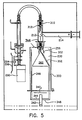
- Figure 5 is an enlarged cross sectional view of an inlet/nozzle scraper assembly and a chamber scraper assembly, taken in the same manner as the cross section of Figure 2.
- The preferred embodiment of the present invention is illustrated in the Figures. Shown in Figures 1-5 is an updraft system suitable for use in handling lightweight particulate combustion by-products, including those materials that tend to accumulate on burner components.
- With reference to Figure 1, the
incinerator 210 of the present invention is preferably a vertically oriented device, having ahousing 212, aprocess gas inlet 214, and aflue gas outlet 216. Thehousing 212 may further contain anaperture 201 through which a pneumatically activated bypass valve (not shown) is connected to a compressed gas line withinhousing 212, andapertures 203 for the attachment of incoming fuel gas, pressurized gases and electrical lines (not shown) to appropriate structures contained within thehousing 212.Control panel 200 may advantageously contain various on/off and reset buttons, status lights and a display window providing operating parameter information, next step instructions and fault diagnostic messages as appropriate.Louvers 266 provide access for cooling air to enterhousing 212. - In operation, process gas containing oxidizable impurities is introduced into the
incinerator 210 through theprocess gas inlet 214, where it is combined with fuel gas (such as natural gas) entering the fuel gas inlet 220 (shown in Figure 2) and with combustion air or other oxygen-containing gas, and is oxidized, generating a flue gas. The flue gas exits thehousing 212 of theincinerator 210 through theflue gas outlet 216, which is preferably situated at the top 222 of theincinerator 210. - The preferred embodiment illustrated in Figures 2-5 includes a number of features that facilitate operation when treating materials that generate particulate by-products and includes features which remove such particulates from interior surfaces of the incinerator.
- With reference to Figure 2, the general design of the
incinerator 210 of the preferred embodiment is illustrated. In this design, theincinerator 210 has ahousing 212 and aprocess gas inlet 214 substantially similar to those of Figure 1. Within thehousing 212 is contained acombustion chamber 230. Exhaust gases leaving thecombustion chamber 230 of this embodiment of theincinerator 210 exit at aflue gas outlet 216. - In most instances, the
incinerator 210 is also provided with apilot light chamber 263. Process gas containing oxidizable impurities is introduced into theincinerator 210 through theprocess gas inlet 214, where it is combined with fuel gas (such as natural gas) entering thefuel gas inlet 220 and with combustion air or other oxygen-containing gas, and is oxidized, generating a flue gas. The flue gas exits thehousing 212 of theincinerator 210 through theflue gas outlet 216 located on top offlue gas plenum 215. - In operation, process gas containing impurities enters the
housing 212 through theprocess gas inlet 214. Thisinlet 214 preferably carries the process gas radially inward to the central axis of theincinerator 210, which runs vertically through the center of theincinerator 210. Theprocess gas inlet 214 then directs the process gas downwardly along the central axis of theincinerator 210. At this point, fuel gas enters through fuel gas inlet hole(s) 223 and is mixed with the process gas. The path of fuel gas frominlet 220 to inlet hole(s) 223 may be directed by a jacket over the outer surface of theprocess gas inlet 214 thereby providing convective cooling to the inside wall ofprocess gas inlet 214. Additionally, nitrogen for flashback protection may be introduced into theprocess gas inlet 214 throughinlet 218. A total gas flow above 28.3 x 103 cm3/minute (1 scfm) ininlet 214 will exceed the flame propagation speed at ordinary temperatures for most combustible mixtures except those containing premixed hydrogen and oxidizer. - The downwardly directed mixture of fuel and process gas is further thoroughly mixed with air as it enters
combustion chamber 230. This mixing is preferably accomplished by means of a ring nozzle which is represented in Figure 2 aselement 224. A sight tube 233 (shown in Figure 3) for attachment of a UV detector is located at the top ofcombustion chamber 230 adjacent to ringnozzle 224. The UV detector (not shown) functions as a control system to monitor the presence of flame within the combustion chamber. In one embodiment, thering nozzle 224 is also connected to apressurized air line 226 which imparts a swirl to the combined fuel gas and process gas. Thering nozzle 224 is advantageously an annular nozzle surrounding the pathway of the process gas as it leaves theprocess gas inlet 214 in a downward direction along the vertical axis of theincinerator 210. Thering nozzle 224 may comprise a plurality of sonic jets directing air or other pressurized gas around and into the process gas to effect mixing of the process gas, the fuel gas, and the air from thering nozzle 224. To the extent that any combustion is occurring at thering nozzle 224, the high velocity within the sonic air jets (which will also function effectively when subsonic) prevents plugging of the jet orifices. Such plugging might otherwise occur through reaction between the injected oxygen and silane in the process gas to form solid reaction products in the jets. It is preferred that the sonic jets are directed not only in a spiral direction, but also are canted downward. This tends to draw the process gas into thecombustion chamber 230, with the sonic jets acting as an ejector pump, preventing back pressure from being exerted on the processgas inlet line 214. Thering nozzle 224 preferably injects air through orifices distributed all the way around theprocess gas inlet 214. - The mixture of fuel gas and process gas exiting the
ring nozzle 224 travels downward into acombustion chamber 230 located vertically below thering nozzle 224 along the vertical axis of theincinerator 210. There the fuel gas and process gases are combined with combustion air that has been preheated by means of aheat exchanger 234. Theheat exchanger 234 in the illustrated embodiment comprises ajacket 236 located radially outwardly from and circumferentially surrounding theouter wall 240 of thecombustion chamber 230. The combustion air is preferably directed into theheat exchanger 234 by means of afan 242, which is preferably located at the bottom 244 of theincinerator 210. Thefan 242 pushes outside air up through abifurcated air pipe 243 into theheat exchanger 234. The combustion air leaves thepipe 243 and travels into theheat exchanger 234, which is preferably annular in cross section. The air then moves upward through aswirl inducing ring 254 in theheat exchanger 234. The swirling air then reverses its upward component of direction 180 degrees as it enters the top of thecombustion chamber 230. Turbulent mixing of the preheated combustion air and the fuel gas and process gas occurs in amixing zone 256 in the top of thecombustion chamber 230. The hot combustion air entering the mixing zone is swirling in the opposite direction of the fuel/process gas stream stirred by the sonic mixing jets, and the relative angular momentums of the swirling streams are such that little or no swirling is present in the downwardly-traveling gas mixture within and exiting the combustion zone. Particulate matter exiting the bottom of thecombustion chamber 230 is normally entrained in the upwardly moving cooling air flow withinflue gas plenum 215. Any dense material falling out of the air flow is collected in acatch tray 250 located beneath the combustion chamber and supported atopbase support 259. The various support mechanisms beneath thecombustion chamber 230 are of an open construction to allow cooling air to pass upwardly past them andpast catch tray 230 intoflue gas plenum 215. - During startup of the incinerator, and as otherwise needed, an igniter 260 (which can be a conventional spark plug) is used to ignite an air/fuel gas mixture created within
pilot chamber 263 to produce a continuous pilot flame extending frompilot chamber 263 into thecombustion chamber 230. (Pilot air inlet 221 and pilotfuel gas inlet 225 are shown in Figure 3). The pilot flame assures ignition of the process gas/fuel/air mixture present within the combustion chamber and is located on the blind side of the optical path provided bysight tube 233 for the UV detector. This insures that the UV detector will see no flame should the main combustion flame extinguish but the pilot flame continue to burn. - Located just below the mixing
zone 256 in the top of thecombustion chamber 230 is aflow director 262 supported by a fixedrod 280. Theflow director 262 urges the downwardly-moving burning gas leaving theprecombustion zone 256 in a radially outward direction. Theflow director 262 may advantageously be conical in configuration, as illustrated in Figure 2, with its apex located in mixingzone 256 and situated symmetrically about the vertical axis of theincinerator 210. - The flue gas generated by the combustion process exits down and out of the
combustion chamber 230. The flue gas then reverses direction 180 degrees as it is entrained in and mixes turbulently with a large volume of cooling air drawn upwardly throughflue gas plenum 215. In one preferred embodiment, the incinerator is adapted to operate with negative pressure applied to the flue gas outlet. This negative pressure, for example, is applied to the ductwork into which the flue gas travels as it leaves theincinerator 210 by a conventional scrubber or other device. Such negative pressure may be used to further cool the flue gas by drawing outside cooling air into the incinerator throughlouvers 266 on thehousing 212 of theincinerator 210. Theselouvers 266 are preferably located below thecombustion chamber 230. Convective cooling of thehousing 212 is assured by the provision for a gap between collar 211 (attached to the external ducting) and the smaller concentric cylindrical portion offlue gas outlet 216, in that some of the cooling air also flows through this gap and must reach it from below by moving upwardly through the space between the inside surfaces ofhousing 212 and the outer surface offlue gas plenum 215. As a result, theouter housing 212 of theincinerator 210 remains cool. In addition, the continuous flow of air through this gap prevents any accumulation of undesirable gas inside the upper portions ofhousing 212 should any internal leaks occur. - Another aspect of the preferred embodiment of the
incinerator 210 that is particularly significant is the provision of scrapers for removal of particulates from interior surfaces of the incinerator. As illustrated in Figures 2,4,5, there is afirst scraper 310, an inlet/nozzle scraper, located withintube 312. This inlet/nozzle scraper 310, as shown in Fig. 4, comprises abody 314, two centeringrings 316 located annularly over thebody 314 for maintaining it centered within thetube 312, alower post 318 extending downwardly from thebody 314, and acap 320 threaded into the top of thebody 314 and compressing aspring 323 inside of thebody 314, which in turn biases apiston 324 downwardly. Thepiston 324 extends through the center of thebody 314 to the bottom thereof.Scraper 310 further comprises one or moreextensible scraper blades 322 extending vertically downward and radially outward from thebody 314, which are spring loaded to extend radially outward against the inside of thetube 312 by means ofcompressed spring 323 andpiston 324. In the illustrated embodiment,multiple blades 322 are shown, albeit it is to be understood that the number of blades may vary without altering the spirit and scope of the invention.Post 318 is provided to dislodge accumulated particulate material at the top of theflow director 262. Atcap 320,scraper 310 is attached to a lead screw/flexible drive device used for rotating, raising and lowering the inlet/nozzle scraper 310 up and down withintube 312, as shown in Figures 2 and 5. Figure 5 shows the two typical extreme positions of movable inlet/nozzle scraper 310. - The rotating, raising and lowering of inlet/
nozzle scraper 310 is accomplished as follows: aflexible drive cable 284 is attached toscraper 310 at one end and to a leadscrew drive mechanism 299 at the other end. Afixed body 286 houses a nut through which thelead screw 288 turns when rotated by a reversingdrive motor 290. As thelead screw 288 advances through fixednut 292 it simultaneously rotates and advancesflexible drive cable 284 which is attached firmly to the end of thelead screw 288. Attached firmly to the other end ofdrive cable 284 is thescraper 310 which then rotates and advances with the drive cable.Drive motor 290 is mounted on the lower end of the lead screw and advances with it. Additionally, a small flow of inert or non reactive gas such as nitrogen is introduced into the fixedbody 286 throughinlet 298 in order to purge the drive cable conduit and keep it free of reactive or corrosive process gases. This purge gas enterstube 312 at the top and flows past the parked inlet/nozzle scraper 310 thereby cooling it, keeping its guide rings 316 open and preventing process gas from entering the portion oftube 312 above the plane of theprocess gas inlet 214. This upper portion oftube 312 in which the scraper resides most of the time is unavoidably heated by radiation from the hot combustion chamber. - Figure 5 indicates how the drive motor housing and mounting are constrained from rotating by
guide rods 294 which slide along avertical guide bar 296 as the motor advances up or down with the rotating lead screw. Reversal of rotation and of advancement direction takes place when electrical limit switches are tripped at the ends of the travel and themotor 290 is reversed. - As rotating inlet/
nozzle scraper 310 advances downward throughtube 312 and past themouth 213 of the processgas inlet tube 214 it dislodges deposited solids from the inner wall of the tube, thereby preventing gradual buildup of solids and eventual plugging ofinlet mouth 213,tube 312 orring nozzle 224. As the inlet/nozzle scraper 310 continues to move down,extensible blades 322 are biased in such a manner that, when they are extended beyond thering nozzle 224, they are able to open up radially outwardly and scrape particulate material lying very near to the sonic mixing jets (not shown) of thering nozzle 224. This is necessary to preserve good mixing in mixingzone 256 where any physical interference between the incoming process gas/fuel mixture and the mixing jets can significantly degrade performance. When inlet/nozzle scraper 310 is withdrawn back intotube 312,blades 322, due to their biasing, may easily be drawn back intoring nozzle 224 andtube 312. An inlet/nozzle scraping cycle is completed when the scraper returns to its parking position at the top of thetube 312 where it resides above the inlet gas flow. One cycle, from top to nozzle and back again, takes about forty seconds to complete. The cycle may be repeated as often as desired, typically once every half hour. - A second, or chamber,
scraper 340 is positioned withincombustion chamber 230 and, as shown in Figures 2 and 5, comprises a center support bearing 342 located on the central axis of thecombustion chamber 230 below the bottom of said chamber; a long radially extending support spoke 344 connected to thebearing 342 which supports a longupright scraper blade 346 extending vertically into thecombustion chamber 230 against the inside wall thereof, preferably extending from bottom to top; a short radially extending support spoke 348 connected to thebearing 342 which supports the bottom end of ashort upright bar 350, which is further connected at its top end at an angle of about 60° to ascraper blade 352 extending vertically along the outside of theconical flow director 262. Center support bearing 342 is rotatably attached at its lower end to a chain drive mechanism (not shown), distal to the central pivotal axis. Bearing 342 is fitted with a sprocket connected by a drive chain to a sprocket on a motor located belowmotor 290. This chamber scraper motor runs continuously and turnschamber scraper 340 slowly at several revolutions per minute. - During the operation of the incinerator of the preferred embodiment, the inlet/
nozzle scraper 310 and thechamber scraper 340 function to remove particulate materials from within thecombustion chamber 230. As noted previously, the inlet/nozzle scraper 310 removes particulates from within thetube 312, from the jets of thering nozzle 224, and from the apex of theflow director 262. Additionally,scraper blades Scraper blade 346 removes particulates from the interior cylindrical wall of thecombustion chamber 230, whilescraper blade 352 removes particulates from the conical surface of theflow director 262. As particulates are dislodged, they drift out the bottom ofchamber 230 and are either entrained into the upwardly moving cooling air withinplenum 215 or else fall out of the flow and intocatch tray 250. As illustrated in the Figures, in the preferred embodiment, the chamber scraper support and drive apparatus, i.e., the spokes, chain, bearing and motor, are located below the combustion chamber and flow reversal plane as characterized by the arrows indicating direction of gas flow, in order to avoid excessive heating or fouling with particulates, and to minimize intrusion into the combustion chamber of mechanical surfaces which can provide a foothold for particulate deposition leading to eventual blockage of the chamber exit. - During the operation of a
typical incinerator 210 having a 5.08 cm [2 inch]process gas inlet 214 and a combustion chamber volume of 0.0094 m3 [1/3 cubic foot], process gases comprising 0 - 84.95 x 103 cm3/minute [0-3 scfm] N2 with 0 - 28.3 x 103 cm3/minute [[0-1 scfm] H2 or O2 and smaller amounts of oxidizable impurities such as arsine, silane, phosphine, diborane and halogenized hydrocarbons are combined with sufficient natural gas or other gaseous fuels to sustain combustion (typically from 0 - 70.8 x 103 cm3/minute [0-2.5 scfm]). Compressed air is introduced into theswirl nozzle 224 at a rate of 14.16 x 10³ - 84.95 x 103 cm3/minute, 552 kPa [0.5 to 3 scfm, 80 psig]. The preheated air from thefan 242 enters the combustion zone at a rate of about 283 x 103 - 1133 x 103 cm3/minute [10-40 scfm], at a preheated temperature of about 400 degrees C. The negative pressure applied to the flue gas outlet draws air and gas out of the incinerator at a rate of about 11.33 x 10⁶ - 16.99 x 106 cm3/minute [400-600 scfm]. - The
incinerator 210 houses a control system with electronic controls, plumbing, automatic valves, various sensors, power supplies and other appurtenances (not shown) generally located in the space belowcatch tray 250 and mounted to vertical panels in the manner illustrated by the mounting offan 242. The controls are operated fromcontrol panel 200. The general nature and functions of the control system will be described briefly. - A microprocessor (such as an Intel 8051, Intel Corp., Santa Clara, CA) works in conjunction with a UV detector/controller (e.g., an Allen Bradley Fireye®, Waltham, Mass.) to operate a number of normally closed solenoid valves, sensors, switches and the like, and to provide status information to the operator. Input gas pressures, operating temperatures, fan pressure, duct draw and natural gas back pressure are sensed and input to the microprocessor. Resident firmware performs a self test and turns on the UV detector/controller if all is well. If the UV detector/controller loses power or fails for any reason the spring loaded fuel gas valve closes, the combustion air fan stops, there is no spark, combustion ceases and the incinerator shuts down. The UV detector/controller has direct control of the essential safety functions (fuel, air, ignition). If the UV detector/controller shuts the system down it cannot be restarted by the microprocessor until the UV controller has been reset manually. The microprocessor prompts the operator that the manual reset is needed and tells when pressing the reset button is likely to be successful. Alternatively, if any of the inputs to the microprocessor indicate a fault, the firmware can instruct the UV detector/controller to shut the system down and the microprocessor can simultaneously take action to notify the operator about the nature of the specific problem and what to do next. For example, if an internal blockage were to restrict the entrance of natural gas into the combustor, the back pressure would begin to rise. Long before the back pressure approaches the line pressure, the back pressure switch will trip and the natural gas valve will close, thereby protecting the gas line from possible back streaming. The microprocessor will sound an audible alarm and place the message "fuel pressure low" in the display window along with instructions about the next action to be taken. Simultaneously the UV detector will sense a flame out condition and its controller will shut the incinerator down. If chamber or exhaust temperatures exceed preset limits during operation, the microprocessor will instruct the UV controller to shut the system down. If any compressed gas pressure falls below its preset limit the microprocessor will close the valve for that gas and similarly call for system shut down. In all such cases the operator is provided with an interlock signal which can be used to automatically shut down his process or, alternatively, the control system will switch a compressed gas solenoid to actuate a pneumatic valve in order to divert the process gas into another operating unit (valve normally diverted). In the event of a scraper failure the microprocessor sounds the alarm and indicates which scraper is out but does not divert the flow or shut down the process, since there is little immediate danger and there is a high probability that the batch can be completed successfully before plugging of the incinerator becomes severe.
Claims (19)
- A device for oxidizing materials in a gas stream, said device including a combustion chamber (230) having a top and a bottom, means for introducing process gas (214) and a source of fuel (220) into the combustion chamber, and a gas outlet (216) for exhaust gas from said combustion chamber, characterised by:
said combustion chamber (230) defining a mixing zone (256);
means (242, 254) for introducing oxygen carrying gas into said combustion chamber (230) in a manner to cause said oxygen carrying gas to swirl about said mixing zone (256) in a first direction;
means (224, 226) for introducing said process gas and source of fuel into said combustion chamber in a manner to cause said process gas and fuel to swirl about said mixing zone in a second direction opposite said first direction to achieve turbulent mixing of said gases and fuel in said mixing zone and
means (262) for directing the gas fuel mixture outwardly toward the wall (240) of said combustion chamber (230) and downwardly as it is burning to produce an exhaust gas,
said gas outlet (216) being adapted to operate in conjunction with means applying negative pressure thereto so as to draw exhaust gas from said combustion chamber. - A device according to Claim 1, characterised in that the mixture directing means (262) has a conical configuration and has an apex at the top thereof.
- A device according to Claim 1, or Claim 2, characterised in that said means for introducing process gas and fuel (224, 226) is located sufficiently below the top of said combustion chamber (230) that solid combustion byproducts do not substantially deposit in said combustion chamber above this means.
- A device according to Claim 1, 2 or 3, characterised in that said means (224, 226) for introducing said process gas and fuel in a swirling manner comprises one or more sonic jets.
- A device according to Claim 4, characterised in that the or each sonic jet is provided on a ring nozzle (224) connected via a line (226) to a source of air under pressure.
- A device according to any one of Claims 1 to 5, characterised in that said means for introducing oxygen carrying gas in a swirling manner comprises a fan (242) which feeds said gas upwardly around the outside of the combustion chamber (230) via a pipe (243) containing swirl rings (254) to an inlet at the top of said combustion chamber.
- A device according to any preceeding Claim, characterised in that a mechanical scraper (310) is provided for removing solid products of combustion from the mixture directing means (262) and from the wall (240) of said combustion chamber (230).
- A device according to any preceeding Claim, characterised in that a mechanical scraper (310) is provided for removing solid products of reaction from the process gas/fuel inlet (214).
- A device according to Claim 7, or 8, characterised in that said scraper (310) comprises one or more extensible blades (322) which are spring loaded to extend radially outward.
- A device according to Claim 7, 8 or 9, characterised in that means (299) are provided for intermittently advancing and retracting said scraper (310).
- A device according to Claim 10, characterised in that means (284) are provided for simultaneously rotating said scraper (310).
- A device according to any preceeding Claim, characterised in that a removable tray (250) is located beneath said combustion chamber (230) for collecting solid products of combustion.
- A method for oxidizing materials in a gas stream comprising the step of introducing fuel and process gas into a combustion chamber (230) that defines a mixing zone (256) and has a gas outlet (216), characterised by the further steps of:
introducing oxygen-carrying gas into said combustion chamber in a manner so that said oxygen carrying gas swirls about said mixing zone (256) in a first direction;
introducing process gas and fuel into said mixing zone (256) in said combustion chamber in a manner so that said process gas and fuel swirls about said mixing zone (256) in a second direction opposite said first direction to achieve turbulent mixing when said swirling gases collide, to thereby form a burning mixture;
directing said burning mixture outwardly and downwardly through said combustion chamber (230) and forming an exhaust gas which exits said combustion chamber; and
inducing a negative pressure on said gas outlet (216) to draw said exhaust gas out of said combustion chamber. - A method according to Claim 13, characterised by preheating said oxygen carrying gas prior to its entry into said combustion chamber (230) with heat from said oxidation of said fuel.
- A method according to Claim 14, characterised in that said preheating step comprises passing said oxygen-carrying gas upward over the outside of said combustion chamber (230).
- A method according to any one of Claims 13 to 15, characterised in that one of said swirling gases is introduced into said combustion chamber (230) radially inwardly of another of said swirling gases, and at a point sufficiently below the top of said combustion chamber (230) that solid products of combustion do not accumulate on said top.
- A method according to any one of Claims 13 to 16, characterised by the step of cooling said exhaust gas by mixing it with cooling air.
- A method according to any one of Claims 13 to 17, characterised by the step of preventing flashback into a conduit supplying process gas into the combustion chamber (230) by reducing the cross-sectional area of the conduit and by introducing sufficient nonflammable gas into said conduit upstream of said chamber (230) that the flow rate of gas in said conduit is greater than the flame propagation speed in the resulting gas mixture.
- A method according to any one of Claims 13 to 18, characterised by the step of mechanically scraping accumulated solid combustion products from the wall (240) of said combustion chamber (230).
Applications Claiming Priority (7)
| Application Number | Priority Date | Filing Date | Title |
|---|---|---|---|
| US33671889A | 1989-04-12 | 1989-04-12 | |
| US336718 | 1989-04-12 | ||
| US35598789A | 1989-05-22 | 1989-05-22 | |
| US355987 | 1989-05-22 | ||
| US48661790A | 1990-02-28 | 1990-02-28 | |
| US486617 | 1990-02-28 | ||
| PCT/US1990/001917 WO1990012636A1 (en) | 1989-04-12 | 1990-04-09 | Incinerator for complete oxidation of impurities in a gas stream |
Publications (3)
| Publication Number | Publication Date |
|---|---|
| EP0467989A1 EP0467989A1 (en) | 1992-01-29 |
| EP0467989A4 EP0467989A4 (en) | 1992-05-20 |
| EP0467989B1 true EP0467989B1 (en) | 1996-07-03 |
Family
ID=27407147
Family Applications (1)
| Application Number | Title | Priority Date | Filing Date |
|---|---|---|---|
| EP90907768A Expired - Lifetime EP0467989B1 (en) | 1989-04-12 | 1990-04-09 | Incinerator for complete oxidation of impurities in a gas stream |
Country Status (7)
| Country | Link |
|---|---|
| EP (1) | EP0467989B1 (en) |
| JP (1) | JP2802544B2 (en) |
| AT (1) | ATE139910T1 (en) |
| AU (1) | AU5562690A (en) |
| CA (1) | CA2051120C (en) |
| DE (1) | DE69027676T2 (en) |
| WO (1) | WO1990012636A1 (en) |
Families Citing this family (10)
| Publication number | Priority date | Publication date | Assignee | Title |
|---|---|---|---|---|
| US5462429A (en) * | 1993-10-20 | 1995-10-31 | Praxair Technology, Inc. | Mechanical wiper for waste gas incinerator |
| US5753201A (en) * | 1994-03-28 | 1998-05-19 | Lin; Ping Wha | Method for manufacturing sulfuric acid |
| US6287534B1 (en) | 1994-03-28 | 2001-09-11 | Ping Wha Lin | Method for manufacturing sulfuric acid |
| US6908297B2 (en) * | 2000-05-26 | 2005-06-21 | Rohm And Haas Company | Hydrogen-fueled flare system |
| JP4848183B2 (en) * | 2005-12-22 | 2011-12-28 | 財団法人日本自動車研究所 | Combustion test equipment |
| CN102200285A (en) * | 2011-03-22 | 2011-09-28 | 创新工程方案有限公司 | Dynamic oxidation of industrial waste gas |
| GB2504468B (en) | 2012-07-27 | 2017-03-22 | Edwards Ltd | Burner Nozzle Reciprocating Scraper Arrangement for Reducing Effluent Gas Deposits |
| JP6777472B2 (en) * | 2016-09-06 | 2020-10-28 | エドワーズ株式会社 | Abatement equipment and deposit removal means used in abatement equipment |
| JP2021046982A (en) * | 2019-09-19 | 2021-03-25 | エドワーズ株式会社 | Gas treatment device and scraper drive device |
| TWI732645B (en) * | 2020-08-05 | 2021-07-01 | 國立臺灣科技大學 | Separating and cooling device and fueling system using the same |
Family Cites Families (26)
| Publication number | Priority date | Publication date | Assignee | Title |
|---|---|---|---|---|
| US329087A (en) * | 1885-10-27 | Eileet othon schabtait | ||
| US857808A (en) * | 1904-12-05 | 1907-06-25 | Boston Crude Oil Burner Co | Hydrocarbon-burner system. |
| US2601041A (en) * | 1949-06-11 | 1952-06-17 | Gilbert & Barker Mfg Co | Controlling mechanism for flue cleaning means for heating apparatus |
| US3268296A (en) * | 1963-04-08 | 1966-08-23 | Hooker Chemical Corp | Process and apparatus for treating gas streams |
| GB1097762A (en) * | 1963-12-12 | 1968-01-03 | British Titan Products | Device for use in oxidation of metal halides |
| JPS489093U (en) * | 1971-06-11 | 1973-02-01 | ||
| BE794276A (en) * | 1972-03-03 | 1973-07-19 | Mo Ni I Proektno Izyskatelsky | PROCESS FOR REMOVING COMBUSTIBLE LIQUID WASTE BY BURNING THEM, AND DEVICE FOR ITS IMPLEMENTATION |
| DE2312902C3 (en) * | 1973-03-15 | 1978-07-06 | Aeg-Elotherm Gmbh, 5630 Remscheid | Device for the heat treatment of workpieces |
| US3831535A (en) * | 1973-11-02 | 1974-08-27 | Mill Conversion Contractor Inc | Wood waste burner system |
| JPS5090158A (en) * | 1973-12-14 | 1975-07-19 | ||
| JPS5751240B2 (en) * | 1974-02-26 | 1982-10-30 | ||
| US3930802A (en) * | 1974-09-16 | 1976-01-06 | Beasley Albert W | Industrial waste gas incinerator |
| JPS6032609B2 (en) * | 1975-10-14 | 1985-07-29 | 日本ゼオン株式会社 | Processing method for gas produced by oxidation reaction |
| DE2643797A1 (en) * | 1976-09-29 | 1978-04-06 | Bayer Ag | METHOD AND DEVICE FOR THERMAL CLEANING OF EXHAUST AIR |
| JPS5392567A (en) * | 1977-01-21 | 1978-08-14 | Nikku Ind Co | Pollutionnfree incineration system for pitch componentsscontaining matter |
| JPS5428479A (en) * | 1977-08-08 | 1979-03-03 | Kurita Water Ind Ltd | Device of treating melted matter |
| JPS54163708A (en) * | 1978-06-16 | 1979-12-26 | Nippon Keikinzoku Sougou Kenki | Tar fume removal in vertical type sederberg*s electrolytic cell and apparatus therefor |
| JPS5777816A (en) * | 1980-10-31 | 1982-05-15 | Matsushita Electric Ind Co Ltd | Gas purifier |
| JPS5828917A (en) * | 1981-08-13 | 1983-02-21 | Hironari Ogawa | Drawer type ash discharging box for incinerator and boiler |
| DE3243395C2 (en) * | 1982-11-24 | 1985-07-25 | Danfoss A/S, Nordborg | Evaporation burners for liquid fuel |
| IT1181772B (en) * | 1985-03-06 | 1987-09-30 | Ital Idee Srl | FREE FLAME BURNER WITH TURBULENT SPRAYING BY COMBUSTION GASES |
| FR2584800B1 (en) * | 1985-07-10 | 1989-12-29 | Buisson Andre | APPARATUS FOR DIRECT HEATING OF ALL GASEOUS FLUIDS (AIR, ETC.) BY MIXING WITH GASES, COMBUSTION PRODUCTS, PROVIDING A PERFECTLY HOMOGENEOUS MIXTURE |
| FR2591509B1 (en) * | 1985-12-17 | 1989-10-27 | Labo Electronique Physique | ANTI-POLLUTION DEVICE FOR THE ELIMINATION OF TOXIC GASES USED IN THE DEVELOPMENT OF GROUP III-V SEMICONDUCTOR MATERIALS. |
| ES2019383B3 (en) * | 1986-05-27 | 1991-06-16 | Ici Plc | METHOD TO INITIATE A PROCESS FOR THE PRODUCTION OF A GASEOUS CURRENT CONTAINING HYDROGEN AND CARBON OXIDES. |
| DE3621914A1 (en) * | 1986-06-30 | 1988-01-07 | Bosch Gmbh Robert | DEVICE FOR BURNING SOLID PARTICLES IN THE EXHAUST GAS FROM COMBUSTION ENGINES |
| DD273008A1 (en) * | 1988-06-15 | 1989-11-01 | Elektromat Veb | DEVICE FOR CLEANING EXHAUST GASES FROM LOW PRESSURE PROCESSES |
-
1990
- 1990-04-09 AU AU55626/90A patent/AU5562690A/en not_active Withdrawn
- 1990-04-09 CA CA002051120A patent/CA2051120C/en not_active Expired - Fee Related
- 1990-04-09 WO PCT/US1990/001917 patent/WO1990012636A1/en not_active Ceased
- 1990-04-09 EP EP90907768A patent/EP0467989B1/en not_active Expired - Lifetime
- 1990-04-09 JP JP2507066A patent/JP2802544B2/en not_active Expired - Lifetime
- 1990-04-09 DE DE69027676T patent/DE69027676T2/en not_active Expired - Fee Related
- 1990-04-09 AT AT90907768T patent/ATE139910T1/en not_active IP Right Cessation
Also Published As
| Publication number | Publication date |
|---|---|
| DE69027676D1 (en) | 1996-08-08 |
| DE69027676T2 (en) | 1996-11-21 |
| CA2051120C (en) | 1999-08-03 |
| CA2051120A1 (en) | 1990-10-13 |
| WO1990012636A1 (en) | 1990-11-01 |
| AU5562690A (en) | 1990-11-16 |
| EP0467989A1 (en) | 1992-01-29 |
| JPH04504613A (en) | 1992-08-13 |
| JP2802544B2 (en) | 1998-09-24 |
| EP0467989A4 (en) | 1992-05-20 |
| ATE139910T1 (en) | 1996-07-15 |
Similar Documents
| Publication | Publication Date | Title |
|---|---|---|
| US5183646A (en) | Incinerator for complete oxidation of impurities in a gas stream | |
| JP2528426B2 (en) | Combustion chamber for burning bulk trash and liquids containing hydrocarbons | |
| US4861262A (en) | Method and apparatus for waste disposal | |
| CA2051120C (en) | Incinerator for complete oxidation of impurities in a gas stream | |
| USRE34298E (en) | Method for waste disposal | |
| US4481889A (en) | Method and apparatus for afterburning flue gases | |
| US5061463A (en) | Coincinerator apparatus and method for processing waste gases | |
| US5374403A (en) | Apparatus for incinerating hazardous waste | |
| US3730112A (en) | Incineration systems and methods | |
| KR0136585B1 (en) | Flame arresting conduct section combustor and method | |
| US4198384A (en) | Multistage incineration of halogenated hydrocarbon containing waste streams | |
| US5328354A (en) | Incinerator with auxiliary gas evacuation system | |
| JP3430295B2 (en) | Method and equipment for reducing dioxin and furan generated during refuse incineration | |
| US5462429A (en) | Mechanical wiper for waste gas incinerator | |
| US4764105A (en) | Waste combustion system | |
| EP0499184B1 (en) | Combustion method for simultaneous control of nitrogen oxides and products of incomplete combustion | |
| US3887336A (en) | Incineration systems and methods | |
| JP7253018B1 (en) | Abatement device and nozzle scraper | |
| KR19980036859A (en) | Dust collector of incinerator | |
| JP2000234724A (en) | DEVICE AND METHOD FOR QUENCHING FOR PREVENTING COMPOSITION OF PCCDs | |
| CN121916470A (en) | Waste lye incineration device and combustion method | |
| NZ213733A (en) | Incinerator system with reburn stage and heat recovery |
Legal Events
| Date | Code | Title | Description |
|---|---|---|---|
| PUAI | Public reference made under article 153(3) epc to a published international application that has entered the european phase |
Free format text: ORIGINAL CODE: 0009012 |
|
| 17P | Request for examination filed |
Effective date: 19911104 |
|
| AK | Designated contracting states |
Kind code of ref document: A1 Designated state(s): AT BE CH DE DK ES FR GB IT LI LU NL SE |
|
| A4 | Supplementary search report drawn up and despatched |
Effective date: 19920402 |
|
| AK | Designated contracting states |
Kind code of ref document: A4 Designated state(s): AT BE CH DE DK ES FR GB IT LI LU NL SE |
|
| 17Q | First examination report despatched |
Effective date: 19930528 |
|
| GRAH | Despatch of communication of intention to grant a patent |
Free format text: ORIGINAL CODE: EPIDOS IGRA |
|
| GRAH | Despatch of communication of intention to grant a patent |
Free format text: ORIGINAL CODE: EPIDOS IGRA |
|
| GRAA | (expected) grant |
Free format text: ORIGINAL CODE: 0009210 |
|
| AK | Designated contracting states |
Kind code of ref document: B1 Designated state(s): AT BE CH DE DK ES FR GB IT LI LU NL SE |
|
| PG25 | Lapsed in a contracting state [announced via postgrant information from national office to epo] |
Ref country code: IT Free format text: LAPSE BECAUSE OF FAILURE TO SUBMIT A TRANSLATION OF THE DESCRIPTION OR TO PAY THE FEE WITHIN THE PRE;WARNING: LAPSES OF ITALIAN PATENTS WITH EFFECTIVE DATE BEFORE 2007 MAY HAVE OCCURRED AT ANY TIME BEFORE 2007. THE CORRECT EFFECTIVE DATE MAY BE DIFFERENT FROM THE ONE RECORDED.SCRIBED TIME-LIMIT Effective date: 19960703 Ref country code: LI Effective date: 19960703 Ref country code: BE Effective date: 19960703 Ref country code: AT Effective date: 19960703 Ref country code: DK Effective date: 19960703 Ref country code: CH Effective date: 19960703 Ref country code: FR Free format text: THE PATENT HAS BEEN ANNULLED BY A DECISION OF A NATIONAL AUTHORITY Effective date: 19960703 Ref country code: ES Free format text: THE PATENT HAS BEEN ANNULLED BY A DECISION OF A NATIONAL AUTHORITY Effective date: 19960703 |
|
| REF | Corresponds to: |
Ref document number: 139910 Country of ref document: AT Date of ref document: 19960715 Kind code of ref document: T |
|
| REF | Corresponds to: |
Ref document number: 69027676 Country of ref document: DE Date of ref document: 19960808 |
|
| PG25 | Lapsed in a contracting state [announced via postgrant information from national office to epo] |
Ref country code: SE Effective date: 19961003 |
|
| EN | Fr: translation not filed | ||
| REG | Reference to a national code |
Ref country code: CH Ref legal event code: PL |
|
| PG25 | Lapsed in a contracting state [announced via postgrant information from national office to epo] |
Ref country code: GB Effective date: 19970409 |
|
| PG25 | Lapsed in a contracting state [announced via postgrant information from national office to epo] |
Ref country code: LU Free format text: LAPSE BECAUSE OF NON-PAYMENT OF DUE FEES Effective date: 19970430 |
|
| PLBE | No opposition filed within time limit |
Free format text: ORIGINAL CODE: 0009261 |
|
| STAA | Information on the status of an ep patent application or granted ep patent |
Free format text: STATUS: NO OPPOSITION FILED WITHIN TIME LIMIT |
|
| 26N | No opposition filed | ||
| PG25 | Lapsed in a contracting state [announced via postgrant information from national office to epo] |
Ref country code: NL Effective date: 19971101 |
|
| GBPC | Gb: european patent ceased through non-payment of renewal fee |
Effective date: 19970409 |
|
| NLV4 | Nl: lapsed or anulled due to non-payment of the annual fee |
Effective date: 19971101 |
|
| REG | Reference to a national code |
Ref country code: GB Ref legal event code: 728V |
|
| PGFP | Annual fee paid to national office [announced via postgrant information from national office to epo] |
Ref country code: DE Payment date: 19980417 Year of fee payment: 9 |
|
| REG | Reference to a national code |
Ref country code: GB Ref legal event code: 728W |
|
| PG25 | Lapsed in a contracting state [announced via postgrant information from national office to epo] |
Ref country code: DE Free format text: LAPSE BECAUSE OF NON-PAYMENT OF DUE FEES Effective date: 20000201 |