EP0467766A1 - Electrostimulation apparatus - Google Patents
Electrostimulation apparatus Download PDFInfo
- Publication number
- EP0467766A1 EP0467766A1 EP91401965A EP91401965A EP0467766A1 EP 0467766 A1 EP0467766 A1 EP 0467766A1 EP 91401965 A EP91401965 A EP 91401965A EP 91401965 A EP91401965 A EP 91401965A EP 0467766 A1 EP0467766 A1 EP 0467766A1
- Authority
- EP
- European Patent Office
- Prior art keywords
- circuit
- voltage
- low voltage
- point
- signaling
- Prior art date
- Legal status (The legal status is an assumption and is not a legal conclusion. Google has not performed a legal analysis and makes no representation as to the accuracy of the status listed.)
- Granted
Links
Images


Classifications
-
- A—HUMAN NECESSITIES
- A61—MEDICAL OR VETERINARY SCIENCE; HYGIENE
- A61H—PHYSICAL THERAPY APPARATUS, e.g. DEVICES FOR LOCATING OR STIMULATING REFLEX POINTS IN THE BODY; ARTIFICIAL RESPIRATION; MASSAGE; BATHING DEVICES FOR SPECIAL THERAPEUTIC OR HYGIENIC PURPOSES OR SPECIFIC PARTS OF THE BODY
- A61H39/00—Devices for locating or stimulating specific reflex points of the body for physical therapy, e.g. acupuncture
- A61H39/002—Using electric currents
-
- A—HUMAN NECESSITIES
- A61—MEDICAL OR VETERINARY SCIENCE; HYGIENE
- A61N—ELECTROTHERAPY; MAGNETOTHERAPY; RADIATION THERAPY; ULTRASOUND THERAPY
- A61N1/00—Electrotherapy; Circuits therefor
- A61N1/18—Applying electric currents by contact electrodes
- A61N1/32—Applying electric currents by contact electrodes alternating or intermittent currents
- A61N1/36—Applying electric currents by contact electrodes alternating or intermittent currents for stimulation
- A61N1/36014—External stimulators, e.g. with patch electrodes
- A61N1/3603—Control systems
- A61N1/36034—Control systems specified by the stimulation parameters
Definitions
- the present invention relates to an electrostimulation apparatus, particularly intended to induce smokers to quit smoking.
- the installation of a staple has the disadvantage of having to be carried out by a specialist. It may present discomfort. It provides permanent stimulation which is not necessary.
- Electrical stimulation has a certain number of advantages since it is not essential to have recourse to a specialist, the effect is powerful and rapid, hygiene is complete, stimulation can intervene whenever the need arises. makes you feel.
- the electrical stimulation devices currently known and used in the state of the art are mainly fixed devices with a mains supply and the use of which is reserved for professionals.
- Other transportable devices can be powered by a renewable energy source. Some consist of a housing, connected to a contact pencil by means of a cord, others include a contact tip.
- the pencil or the contact point When a user implements them by application on a variable number of stimulation points whose mapping is precise, the pencil or the contact point transmit a series of electrical impulses, felt by the nervous system like tingling.
- the subject of the present invention is an electro-stimulation device implementing this discovery, and having other advantageous characteristics described below.
- the present invention therefore relates to an electro-stimulation device consisting of an autonomous housing comprising at least one energy source, a contact end intended to be applied to the skin of a user, so as to transmit to the skin a series of repetitive electrical discharges, characterized in that the apparatus comprises means for stabilizing at least one parameter characterizing the series of discharges. Said means for stabilizing at least one parameter characterizing the series of discharges can stabilize the maximum electrical intensity of the discharges and / or the frequency of the discharges.
- the device may include a first signaling means for signaling the progress of the device.
- the device may also include a second signaling means for signaling wear of the energy source such that the intensity of the discharges can no longer be kept constant.
- the apparatus also comprises means for stopping the emission of electric discharges in the event of detection of wear of the energy source such that the intensity of the discharges can no longer be kept constant.
- the box is closed so that it cannot be opened by a user, so that it cannot replace the energy source after the emission of electric discharges has been stopped, following detection wear of the energy source such that the intensity of the discharges can no longer be kept constant.
- the housing may contain an electronic circuit comprising a power supply connected to an oscillator and to a low voltage detection circuit, itself connected to said second signaling means and to the oscillator so that when the low voltage detection circuit detects a supply voltage below a certain threshold, said low voltage detection circuit sends a signal to the oscillator to block the operation of said oscillator, and causes the emission of a low voltage signal by said second means of signaling, said oscillator being connected to a control circuit for amplifying a periodic signal at the output of the oscillator, said control circuit being itself connected to said first signaling means, for emitting an operating signal from the device, and said control circuit also being connected to a voltage conversion circuit for raising the voltage of the amplified signal p ar the circuit of control, said conversion circuit being provided with a circuit for adjusting the intensity of electric discharges and connected to an electrode extending to the end of the contract.
- an electronic circuit comprising a power supply connected to an oscillator and to a low voltage detection circuit, itself connected to said second signaling means and
- the first signaling means and the second signaling means consist of a two-color light-emitting diode which can light up in two different colors, a first color signaling a supply voltage too low and a second color signaling the operation of the device. .
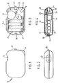
- Figures 1 and 2 show the external form of an example of an electro-stimulation device according to the invention.
- This has the form of a flattened housing 10, of size to be held by hand, having two faces having substantially the shape of rectangles with rounded corners. From one of the rounded corners is formed a contact end 11.
- the housing further comprises an adjustment wheel 12 and an indicator, preferably a two-color light-emitting diode D1, which can light up in green or red.
- the rotation of the dial 12 has the effect of triggering the emission of electrical pulses by the contact end 11, and regulating the peak intensity of said pulses.
- the operation of the device is displayed by a flashing green light emitted by the light-emitting diode D1.
- the case has a length of 8 cm, a width of 5.2 cm and a thickness of 2.4 cm. It can therefore easily be slipped into a pocket clothing, and thus remain within reach of the user to be available when he feels the need to smoke.
- the electro-stimulation device uses batteries. When the batteries are sufficiently spent so that the intensity of the discharges can no longer be kept constant by the device, the light-emitting diode D1 displays a solid red color and the emission of the electrical pulses is cut off. The device must then be discarded.
- the housing 10 cannot be opened without being damaged, which prevents the user from changing the batteries. This prevents the user from replacing the used batteries with different batteries, which could have electrical characteristics sufficiently different from those of the original batteries to compromise the efficiency of the device.
- the device it is essential, for the device to give electrical discharges of sufficient intensity, that the batteries have a low internal resistance.
- the batteries could for example be of the alkaline manganese type, but zinc-carbon batteries of the same nominal voltage would not be suitable.
- FIGS 3 and 4 show the interior arrangement of the housing 10.
- the housing is divided into two shells 21 and 22, which are assembled together so that they cannot be separated by a user.
- the shell 21 may comprise two tenons 23 and 24 adapted to fit into two respective mortises 25 and 26 produced on the shell 22. Tenons and mortises are permanently fixed by gluing.
- a support plate 20 carrying different electronic components, and on which an electrical circuit is printed.
- the support plate can be fixed by any known means.
- the shell 22 has two elastic arms 27. Each arm 27 extends from the shell 22 to an end having a notch in which an edge of the plate 20 is adapted to snap.
- the plate 20 is pierced with a hole and the shell 22 has a lug 28 having a shoulder, said lug being adapted to fit into the hole in the plate 20.
- the fixing of the plate 20 is therefore done by fitting of the hole in the plate 20 on the lug 28, up to the abutment of said shoulder, and by simultaneous snap-fastening on the elastic arms 27.
- the plate 20 has two faces, a first face of which is represented in FIG. 3. On this first face are fixed the PL1 batteries, here four 1.5 V alkaline manganese batteries, connected in series, the thumb wheel 12, the diode electroluminescent D1, a transformer TR1 and a capacitor C1 whose role will be explained below, and an output electrode S1 extending to the contact end 11.
- the shells 21 and 22 have recesses to allow passage to the thumb wheel 12, to the light-emitting diode D1 and to the electrode S1.
- the shell 23 further comprises a rib 29 intended to hold the batteries PL1 in place.
- a second face of the support plate 20 is shown in Figure 5. On this face is printed an electrical circuit (not shown) to which are connected various electronic components which will be described in detail below.
- FIG. 6 is a block diagram of the electronic circuit of the embodiment of the invention of FIGS. 1 to 5.
- This circuit comprises an electrical supply 30, connected to an oscillator 31 and to a low voltage detection circuit 32, itself - even connected to the oscillator 31 and to the light-emitting diode D1.
- the circuit 32 detects a voltage below a certain threshold at the output of the power supply 30, it causes the red color of the two-color light-emitting diode D1 to light up and transmits a low voltage signal to the oscillator 31.
- the oscillator 31 is connected to a control circuit 33; as long as the oscillator does not receive said low voltage signal, it transmits electrical pulses to the control circuit 33, at a frequency between 3 and 8 Hz for example. When it receives said low voltage signal, the oscillator 31 does not transmit an electrical pulse to the control circuit 33.
- the control circuit 33 is connected to the light-emitting diode D1 and to the LV / HV conversion circuit 34. When 'it receives pulses, the control circuit 33 transmits to circuit 34 a series of pulses of greater electrical power, and causes the intermittent lighting of the green color of the two-color light-emitting diode D1.
- the conversion circuit 34 raises the voltage of the electrical pulses, for example up to 500 V, and transmits them to the output electrode 31.
- the circuit 34 is connected to a circuit 35 allowing the electrical intensity to be adjusted. pulses emitted by the electrode S1.
- FIG. 7 presents a detailed diagram of the electronic circuit of FIG. 6.
- the supply circuit consists of four 1.5 V PL1 batteries of alkaline-manganese type connected in series, so as to produce a nominal voltage of 6 V
- a switch I is mounted in series with the PL1 batteries.
- the switch is an end of stroke contact of the thumb wheel 12.
- the voltage conversion circuit includes a transformer TR1 with a primary winding and a secondary winding.
- the primary winding is connected between line 40 and point 54, while the secondary winding is connected between line 40 and a point 55 common with the output control circuit.
- the voltage between point 55 and line 40 here is 500 V.
- the multivibrator IC1 associated with the resistors R5, R6 and the capacitor C1, delivers a low power signal at its output 3, in the form of a periodic voltage signal in slots, of frequency for example equal to 5 Hz. If Vo is the voltage produced by the batteries PL1, the potential difference between line 41 and output 3 varies periodically between + Vo and - Vo, at the frequency of 5 Hz in this particular example.
- the transformer TR1 raises the voltage, so that it delivers between line 40 and point 55 voltage pulses of 500 V, at the frequency of 5 Hz in this particular example.
- the maximum value of the output current, passing through the skin of the user lying between the terminals of the electrode S1, is fixed by the potentiometer Po, actuated by the wheel 12.
- the transistor T1 becomes saturated.
- the potential of point 44 therefore increases enough to light up the diode D1 in red, and, due to the higher current passing through the resistor R13, the potential of point 46 increases enough to make the transistor T5 saturated, which short-circuits the capacitor C1, which stops the oscillator, whose output 3 remains at the voltage + Vo.
- the device can therefore no longer deliver electrical pulses at the output of the electrode S1, and must then be discarded.
- the voltage of 4.2 V corresponds to a voltage of each battery of 1.05 V.
- This limiting voltage therefore does not correspond to total wear of the batteries, where the voltage at the terminals of each battery is rather close to 0.8 V, but corresponds to battery wear such that the intensity of electric discharges can no longer be kept constant.
- the internal resistance of the batteries which increases when the voltage at the terminals of the batteries decreases, becomes too high for the electric current necessary to ensure the effectiveness of stimulation is provided.
Abstract
Description
La présente invention concerne un appareil d'éléctro-stimulation, particulièrement destiné à induire les fumeurs à la désaccoutumance du tabac.The present invention relates to an electrostimulation apparatus, particularly intended to induce smokers to quit smoking.
De nombreuses méthodes ont été expérimentées dans le domaine de la désaccoutumance du tabac. On peut citer par exemple les médicaments à base de lobéline, de quinine, de nicotine, et les systèmes tels que l'acuponcture ou de stimulation auriculaire obtenue par l'implantation d'une agraphe ou d'aiguilles ou encore par stimulation électrique.Many methods have been tried in the field of smoking cessation. Mention may be made, for example, of drugs based on lobelin, quinine, nicotine, and systems such as acupuncture or atrial stimulation obtained by implanting a staple or needles or even by electrical stimulation.
La pose d'une agraphe présente l'inconvénient de devoir être réalisée par un spécialiste. Elle peut présenter une gêne. Elle réalise une stimulation permanente qui n'est pas nécessaire.The installation of a staple has the disadvantage of having to be carried out by a specialist. It may present discomfort. It provides permanent stimulation which is not necessary.
L'implantation d'aiguilles est une méthode délicate, qui doit être réalisée par un spécialiste dans des conditions d'hygiène draconiennes.The implantation of needles is a delicate method, which must be carried out by a specialist under draconian hygienic conditions.
La stimulation électrique présente un certain nombre d'avantages puisqu'il n'est pas indispensable d'avoir recours à un spécialiste, l'effet est puissant et rapide, l'hygiène est complète, la stimulation peut intervenir chaque fois que le besoin se fait sentir.Electrical stimulation has a certain number of advantages since it is not essential to have recourse to a specialist, the effect is powerful and rapid, hygiene is complete, stimulation can intervene whenever the need arises. makes you feel.
Les appareils de stimulation électrique actuellement connus et utilisés dans l'état de l'art sont principalement des appareils fixes dotés d'une alimentation sur le secteur et dont l'utilisation est réservée aux professionnels.The electrical stimulation devices currently known and used in the state of the art are mainly fixed devices with a mains supply and the use of which is reserved for professionals.
D'autres appareils, transportables, peuvent être quant à eux alimentés par une source d'énergie renouvelable. Certains se composent d'un boîtier, connecté à un crayon de contact par l'intermédiaire d'un cordon, d'autres comportent une pointe de contact.Other transportable devices can be powered by a renewable energy source. Some consist of a housing, connected to a contact pencil by means of a cord, others include a contact tip.
Lorsqu'un utilisateur les met en oeuvre par application sur un nombre variable de points de stimulation dont la cartographie est pécisée, le crayon ou la pointe de contact transmettent une série d'impulsions éléctriques, ressenties par le système nerveux comme des fourmillements.When a user implements them by application on a variable number of stimulation points whose mapping is precise, the pencil or the contact point transmit a series of electrical impulses, felt by the nervous system like tingling.
Mais ces appareils ne sont pas toujours efficaces; leur fonctionnement peut être pertubé par un certain nombre de facteurs tant au niveau de la connectique de la liaison appareil/cordon lorsque tel est le cas, qu'au niveau plus général de l'instabilité de certaines grandeurs éléctriques provoquée par la variation du niveau de charge de la source d'énergie renouvelable.But these devices are not always effective; their operation can be disturbed by a certain number of factors both at the level of the connection of the device / cord link when this is the case, and at the more general level of the instability of certain electrical quantities caused by the variation of the level of charge of the renewable energy source.
Le demandeur a récemment découvert que la stabilisation des dites grandeurs électriques à des valeurs constantes, en particulier pour la fréquence et l'intensité de pointe, ceci quel que soit le niveau de charge de la source d'énergie dont les spécifications constituent par ailleurs un élément indissociable de l'ensemble, améliore grandement l'efficacité des dispositifs de stimulation électrique du genre en question.The applicant has recently discovered that the stabilization of said electrical quantities at constant values, in particular for the peak frequency and intensity, this regardless of the charge level of the energy source, the specifications of which moreover constitute a inseparable from the whole, greatly improves the efficiency of electrical stimulation devices of the kind in question.
La présente invention a pour objet un appareil d'électro-stimulation mettant en oeuvre cette découverte, et présentant d'autres caractéristiques avantageuses décrites ci-après.The subject of the present invention is an electro-stimulation device implementing this discovery, and having other advantageous characteristics described below.
La présente invention a donc pour objet un appareil d'électro-stimulation constitué d'un boîtier autonome comportant au moins une source d'énergie, une extrémité de contact destinée à être appliquée sur la peau d'un utilisateur, de façon à transmettre à la peau une série de décharges électriques répétitives, caractérisé en ce que l'appareil comporte des moyens pour stabiliser au moins un paramètre caractérisant la série de décharges. Lesdits moyens pour stabiliser au moins un paramètre caractérisant la série de décharges peuvent stabiliser l'intensité électrique maximale des décharges et/ou la fréquence des décharges. L'appareil peut comporter un premier moyen de signalisation pour signaler la marche de l'appareil. L'appareil peut aussi comporter un deuxième moyen de signalisation pour signaler une usure de la source d'énergie telle que l'intensité des décharges ne puisse plus être maintenue constante. Avantageusement, l'appareil comporte aussi des moyens pour arrêter l'émission des décharges électriques en cas de détection d'une usure de la source d'énergie telle que l'intensité des décharges ne puisse plus être maintenue constante.The present invention therefore relates to an electro-stimulation device consisting of an autonomous housing comprising at least one energy source, a contact end intended to be applied to the skin of a user, so as to transmit to the skin a series of repetitive electrical discharges, characterized in that the apparatus comprises means for stabilizing at least one parameter characterizing the series of discharges. Said means for stabilizing at least one parameter characterizing the series of discharges can stabilize the maximum electrical intensity of the discharges and / or the frequency of the discharges. The device may include a first signaling means for signaling the progress of the device. The device may also include a second signaling means for signaling wear of the energy source such that the intensity of the discharges can no longer be kept constant. Advantageously, the apparatus also comprises means for stopping the emission of electric discharges in the event of detection of wear of the energy source such that the intensity of the discharges can no longer be kept constant.
Avantageusement, le boîtier est fermé de façon à ne pas pouvoir être ouvert par un utilisateur, de façon à ce qu'il ne puisse pas remplacer la source d'énergie après que l'émission des décharges électriques a été arrêtée, suite à la détection d'une usure de la source d'énergie telle que l'intensité des décharges ne puisse plus être maintenue constante.Advantageously, the box is closed so that it cannot be opened by a user, so that it cannot replace the energy source after the emission of electric discharges has been stopped, following detection wear of the energy source such that the intensity of the discharges can no longer be kept constant.
Le boîtier peut contenir un circuit électronique comprenant une alimentation connectée à un oscillateur et à un circuit de détection de tension basse, lui-même connecté audit deuxième moyen de signalisation et à l'oscillateur de façon que lorsque le circuit de détection de tension basse détecte une tension de l'alimentation inférieure à un certain seuil, ledit circuit de détection de tension basse envoie un signal à l'oscillateur pour bloquer le fonctionnement dudit oscillateur, et provoque l'émission d'un signal de tension basse par ledit deuxième moyen de signalisation, ledit oscillateur étant connecté à un circuit de commande pour amplifier un signal périodique en sortie de l'oscillateur, ledit circuit de commande étant lui-même connecté audit premier moyen de signalisation, pour émettre un signal de marche de l'appareil, et ledit circuit de commande étant aussi connecté à un circuit de conversion de tension pour élever la tension du signal amplifié par le circuit de commande, ledit circuit de conversion étant doté d'un circuit de réglage de l'intensité des décharges électriques et connecté à une électrode s'étendant jusqu'à l'extrémité de contract.The housing may contain an electronic circuit comprising a power supply connected to an oscillator and to a low voltage detection circuit, itself connected to said second signaling means and to the oscillator so that when the low voltage detection circuit detects a supply voltage below a certain threshold, said low voltage detection circuit sends a signal to the oscillator to block the operation of said oscillator, and causes the emission of a low voltage signal by said second means of signaling, said oscillator being connected to a control circuit for amplifying a periodic signal at the output of the oscillator, said control circuit being itself connected to said first signaling means, for emitting an operating signal from the device, and said control circuit also being connected to a voltage conversion circuit for raising the voltage of the amplified signal p ar the circuit of control, said conversion circuit being provided with a circuit for adjusting the intensity of electric discharges and connected to an electrode extending to the end of the contract.
Avantageusement, le premier moyen de signalisation et le deuxième moyen de signalisation consistent en une diode électroluminescente bicolore pouvant s'éclairer de deux couleurs différentes, une première couleur signalant une tension d'alimentation trop basse et une deuxième couleur signalant la marche de l'appareil.Advantageously, the first signaling means and the second signaling means consist of a two-color light-emitting diode which can light up in two different colors, a first color signaling a supply voltage too low and a second color signaling the operation of the device. .
D'autres caractéristiques et avantages de l'invention apparaîtront au cours de la description détaillée qui suit, donnée à titre d'exemple non limitatif, en regard des dessins joints, sur lesquels :
- la figure 1 est une vue de côté du boîtier d'une forme préférée de réalisation de l'invention,
- la figure 2 est une vue de dessus du boîtier de la figure 1,
- la figure 3 est une vue de côté du boîtier de la figure 1, ouvert, montrant une première face de la plaque support du circuit électronique de l'appareil,
- la figure 4 est une vue en coupe selon la ligne IV-IV du boîtier de la figure 1,
- la figure 5 est une vue de la deuxième face de la plaque support de la figure 3, à une échelle légèrement réduite,
- la figure 6 est un schéma synoptique du circuit électronique de la forme de réalisation de l'invention des figures 1 à 5, et
- la figure 7 est un schéma détaillé du circuit électronique de la figure 6.
- FIG. 1 is a side view of the housing of a preferred embodiment of the invention,
- FIG. 2 is a top view of the box of FIG. 1,
- FIG. 3 is a side view of the box of FIG. 1, open, showing a first face of the support plate of the electronic circuit of the device,
- FIG. 4 is a sectional view along line IV-IV of the box of FIG. 1,
- FIG. 5 is a view of the second face of the support plate of FIG. 3, on a slightly reduced scale,
- FIG. 6 is a block diagram of the electronic circuit of the embodiment of the invention of FIGS. 1 to 5, and
- FIG. 7 is a detailed diagram of the electronic circuit of FIG. 6.
Les figures 1 et 2 présentent la forme extérieure d'un exemple d'appareil d'électro-stimulation selon l'invention. Celui-ci a la forme d'un boîtier applati 10, de taille à être tenu à la main, présentant deux faces ayant sensiblement la forme de rectangles à coins arrondis. A partir de l'un des coins arrondis est réalisée une extrémité de contact 11. Le boîtier comporte en outre une molette de réglage 12 et un voyant, de préférence une diode électroluminescente D1 bicolore, qui peut s'éclairer en vert ou en rouge.Figures 1 and 2 show the external form of an example of an electro-stimulation device according to the invention. This has the form of a
Lorsqu'un utilisateur ressent le besoin de fumer, il applique l'extrémité de contact 11 en un point de sa peau, de préférence sur une oreille, et tourne la molette 12. La rotation de la molette 12 a pour effet de déclencher l'émission d'impulsions électriques par l'extrémité de contact 11, et de régler l'intensité de pointe desdites impulsions. La marche de l'appareil est visualisée par une lumière verte clignotante émise par la diode électroluminescente D1.When a user feels the need to smoke, he applies the contact end 11 to a point on his skin, preferably on one ear, and turns the
Dans cet exemple, le boîtier a une longueur de 8 cm, une largeur de 5,2 cm et une épaisseur de 2,4 cm. Il peut donc facilement être glissé dans une poche de vêtement, et ainsi rester à portée de la main de l'utilisateur pour être disponible au moment où il ressent le besoin de fumer.In this example, the case has a length of 8 cm, a width of 5.2 cm and a thickness of 2.4 cm. It can therefore easily be slipped into a pocket clothing, and thus remain within reach of the user to be available when he feels the need to smoke.
L'appareil d'électro-stimulation fonctionne à l'aide de piles. Lorsque les piles sont suffisamment usées pour que l'intensité des décharges ne puisse plus être maintenue constante par l'appareil, la diode électroluminescente D1 affiche une couleur rouge continue et l'émission des impulsions électriques est coupée. L'appareil doit alors être jeté.The electro-stimulation device uses batteries. When the batteries are sufficiently spent so that the intensity of the discharges can no longer be kept constant by the device, the light-emitting diode D1 displays a solid red color and the emission of the electrical pulses is cut off. The device must then be discarded.
En effet, le boîtier 10 ne peut pas être ouvert sans être endommagé, ce qui empêche l'utilisateur de changer les piles. Ceci évite que l'utilisateur ne remplace les piles usagées par des piles différentes, qui pourraient avoir des caractéristiques électriques suffisamment différentes de celles des piles initiales pour compromettre l'efficacité de l'appareil.Indeed, the
En effet, il est indispensable, pour que l'appareil donne des décharges électriques d'intensité suffisante, que les piles aient une résistance interne faible. Les piles pourront par exemple être du type alcalines manganèse, mais des piles zinc-carbone de même tension nominale ne pourraient pas convenir.Indeed, it is essential, for the device to give electrical discharges of sufficient intensity, that the batteries have a low internal resistance. The batteries could for example be of the alkaline manganese type, but zinc-carbon batteries of the same nominal voltage would not be suitable.
Les figures 3 et 4 montrent l'agencement intérieur du boîtier 10. Le boîtier se divise en deux coques 21 et 22, qui sont assemblées l'une à l'autre de façon à ne pas pouvoir être séparées par un utilisateur. Par exemple, la coque 21 peut comporter deux tenons 23 et 24 adaptés à s'emboîter dans deux mortaises respectives 25 et 26 réalisées sur la coque 22. Tenons et mortaises sont fixés définitivement par collage.Figures 3 and 4 show the interior arrangement of the
A l'intérieur du boîtier 10 est fixée une plaque support 20, portant différents composants électroniques, et sur laquelle est imprimé un circuit électrique. La plaque support peut être fixée par tout moyen connu. Par exemple, la coque 22 comporte deux bras élastiques 27. Chaque bras 27 s'étend à partir de la coque 22 jusqu'à une extrémité présentant une encoche dans laquelle un bord de la plaque 20 est adapté à s'encliqueter. De plus, la plaque 20 est percée d'un trou et la coque 22 comporte un ergot 28 présentant un épaulement, ledit ergot étant adapté à s'emboîter dans le trou de la plaque 20. La fixation de la plaque 20 se fait donc par emboîtement du trou de la plaque 20 sur l'ergot 28, jusqu'en butée dudit épaulement, et par encliquetage simultané sur les bras élastiques 27.Inside the
La plaque 20 comporte deux faces, dont une première face est représentée à la figure 3. Sur cette première face sont fixées les piles PL1, ici quatre piles alcalines au manganèse de 1,5 V, connectées en série, la molette 12, la diode électroluminescente D1, un transformateur TR1 et un condensateur C1 dont le rôle sera précisé ci-dessous, et une électrode de sortie S1 s'étendant jusqu'à l'extrémité de contact 11. Les coques 21 et 22 comportent des évidements pour laisser le passage à la molette 12, à la diode électroluminescente D1 et à l'électrode S1. La coque 23 comporte en outre une nervure 29 destinée à maintenir en place les piles PL1.The
Une deuxième face de la plaque support 20 est représentée à la figure 5. Sur cette face est imprimé un circuit électrique (non représenté) auquel sont connectés divers composants électroniques qui seront dits en détail ci-après.A second face of the
La figure 6 est un schéma synoptique du circuit électronique de la forme de réalisation de l'invention des figures 1 à 5. Ce circuit comporte une alimentation électrique 30, connectée à un oscillateur 31 et à un circuit de détection de tension basse 32, lui-même connecté à l'oscillateur 31 et à la diode électroluminescente D1. Lorsque le circuit 32 détecte une tension inférieure à un certain seuil en sortie de l'alimentation 30, il provoque l'allumage de la couleur rouge de la diode électroluminescente bicolore D1 et transmet à l'oscillateur 31 un signal de tension basse.FIG. 6 is a block diagram of the electronic circuit of the embodiment of the invention of FIGS. 1 to 5. This circuit comprises an
L'oscillateur 31 est connecté à un circuit de commande 33 ; tant que l'oscillateur ne reçoit pas ledit signal de tension basse, il transmet au circuit de commande 33 des impulsions électriques, à une fréquence comprise entre 3 et 8 Hzpar exemple. Lorsqu'il reçoit ledit signal de tension basse, l'oscillateur 31 ne transmet pas d'impulsion électrique au circuit de commande 33. Le circuit de commande 33 est connecté à la diode électroluminescente D1 et au circuit de conversion BT/HT 34. Lorsqu'il reçoit des impulsions, le circuit de commande 33 transmet au circuit 34 une série d'impulsions de plus grande puissance électrique, et provoque l'allumage intermittent de la couleur verte de la diode électroluminescente bicolore D1. Le circuit de conversion 34 élève la tension des impulsions électriques, par exemple jusqu'à 500 V, et les transmet à l'électrode de sortie 31. De plus, le circuit 34 est connecté à un circuit 35 permettant de régler l'intensité électrique des impulsions émises par l'électrode S1.The
La figure 7 présente un schéma détaillé du circuit électronique de la figure 6. Le circuit d'alimentation est constitué de quatre piles PL1 de 1,5 V de type alcalines-manganèse montées en série, de façon à produire une tension nominale de 6 V. Un interrupteur I est monté en série avec les piles PL1. Avantageusement, l'interrupteur est un contact de fin de course de la molette 12.FIG. 7 presents a detailed diagram of the electronic circuit of FIG. 6. The supply circuit consists of four 1.5 V PL1 batteries of alkaline-manganese type connected in series, so as to produce a nominal voltage of 6 V A switch I is mounted in series with the PL1 batteries. Advantageously, the switch is an end of stroke contact of the
Du circuit d'alimentation partent deux lignes électriques 40 et 41. Entre les deux lignes 40 et 41 est tout d'abord connecté le circuit de détection de tension base qui se compose :
- de deux résistances R1 et R2 montées en diviseur de tension, la résistance R1 étant connectée à la
ligne 40, la résistance R2 étant connectée à la résistance R1 en un point 42 et à laligne 41. Dans cet exemple R1 a une valeur de 33 kΩ et R2 de 43 kΩ ; - d'un premier transistor T1, de type NPN, dont la base est connectée au point 42;
- d'une résistance R3, ici de valeur 15 kΩ, connectée au collecteur du transistor T1 en
un point 43, et à laligne 40; - d'un transistor T2, de type NPN, dont la base est connectée au
point 43 et le collecteur à laligne 40; - d'une résistance R4, ici de valeur 33 kΩ, connecté entre
un point 44 relié à l'émetteur du transistor T1et un point 45 relié à l'émetteur du transistor T2; - de la diode électroluminescente bicolore D1, dont une borne permettant son éclairage en rouge est connecté au
point 44, et une autre borne est connectée à laligne 41, enun point 56 ; - de deux résistances R12 et R13 montées en diviseur de tension. Dans cet exemple, la résistance R12 vaut 10 kΩ et la résistance
R13 vaut 3,8 kΩ. La résistance R12 est connectée aupoint 45, et la résistance R13 est connectée à la résistance R12 enun point 46, et à laligne 41 ; - d'un transistor T5 de type NPN dont la base est connectée au
point 46, l'émetteur à laligne 41, et le collecteur est connecté enun point 47 du circuit oscillateur.
- two resistors R1 and R2 mounted as a voltage divider, the resistor R1 being connected to
line 40, the resistor R2 being connected to the resistor R1 at a point 42 and atline 41. In this example R1 has a value of 33 kΩ and R2 of 43 kΩ; - a first transistor T1, of NPN type, the base of which is connected to point 42;
- a resistor R3, here with a value of 15 kΩ, connected to the collector of transistor T1 at a
point 43, and toline 40; - a transistor T2, of NPN type, the base of which is connected to point 43 and the collector to
line 40; - a resistor R4, here with a value of 33 kΩ, connected between a
point 44 connected to the emitter of the transistor T1 and apoint 45 connected to the emitter of the transistor T2; - two-color light-emitting diode D1, one terminal of which allows it to be lit in red is connected to point 44, and another terminal is connected to
line 41, atpoint 56; - two resistors R12 and R13 mounted as a voltage divider. In this example, the resistor R12 is worth 10 kΩ and the resistor R13 is worth 3.8 kΩ. Resistor R12 is connected to point 45, and resistor R13 is connected to resistor R12 at
point 46, and toline 41; - an NPN type T5 transistor, the base of which is connected to point 46, the emitter to line 41, and the collector is connected to point 47 of the oscillator circuit.
Le circuit oscillateur comporte:
- un multivibrateur astable IC1 doté de sept bornes de connexion, dont deux bornes 4
et 5 sont connectées à laligne 40, une borne 1 est connectée à laligne 41, et une bornede sortie 3 est connectée à un point 49 du circuit de commande, - une résistance R5 connectée entre la ligne 40
et un point 48 relié à une borne 7 du multivibrateur IC1 ; la résistance R5 a ici une valeur de 160 kΩ; - une résistance R6 connectée à deux bornes 2
et 6 du multivibrateur IC1 ; la résistance R6 a ici une valeur de 47 kΩ; - un condensateur C1, ici de capacité 1 µF, connecté entre le
point 47 et laligne 41.
- an astable multivibrator IC1 with seven connection terminals, two
terminals 4 and 5 of which are connected toline 40, oneterminal 1 is connected toline 41, and oneoutput terminal 3 is connected to a point 49 of the control circuit , - a resistor R5 connected between
line 40 and apoint 48 connected to a terminal 7 of the multivibrator IC1; resistance R5 here has a value of 160 kΩ; - a resistor R6 connected to two
terminals - a capacitor C1, here with a capacity of 1 μF, connected between
point 47 andline 41.
Le circuit de commande comprend:
- une résistance R7, ici de valeur 10 kΩ, connectée au point 49 ;
- une résistance R8, ici de valeur 10 kΩ, connectée à la résistance R7 en
un point 50 et à laligne 40 ; - un transistor T3, de type PNP, dont la base est connectée au
point 50 et l'émetteur est connecté à laligne 40 ; - une résistance R9, ici de valeur 100Ω , connectée en
un point 51 au collecteur du transistor T3; - la diode électroluminescente D1 bicolore, dont une borne permettant son éclairage en vert est connectée à la résistance R9 en
un point 52, et dont une autre borne est connectée à laligne 41 enun point 57; - la résistance R10, ici de valeur 410Ω connectée au
point 51; - le transistor T4, de type NPN, dont la base est connectée à la résistance R10 en
un point 53, dont l'émetteur est connecté à laligne 41, et dont le collecteur est connecté au circuit de conversion de tension enun point 54.
- a resistor R7, here with a value of 10 kΩ, connected to point 49;
- a resistor R8, here with a value of 10 kΩ, connected to the resistor R7 at a
point 50 and toline 40; - a transistor T3, of PNP type, the base of which is connected to point 50 and the emitter is connected to
line 40; - a resistor R9, here with a value of 100Ω, connected at a
point 51 to the collector of transistor T3; - the two-color light-emitting diode D1, one terminal of which allows it to be lit in green, is connected to the resistor R9 at a
point 52, and another terminal of which is connected to theline 41 at apoint 57; - resistance R10, here with a value of 410Ω connected to point 51;
- the transistor T4, of the NPN type, the base of which is connected to the resistor R10 at a
point 53, the emitter of which is connected to theline 41, and the collector of which is connected to the voltage conversion circuit at apoint 54.
Le circuit de conversion de tension comprend un transformateur TR1 doté d'un enroulement primaire et d'un enroulement secondaire. L'enroulement primaire est connecté entre la ligne 40 et le point 54, tandis que l'enroulement secondaire est connecté entre la ligne 40 et un point 55 commun avec le circuit de réglage de sortie. La tension entre le point 55 et la ligne 40 est ici de 500 V.The voltage conversion circuit includes a transformer TR1 with a primary winding and a secondary winding. The primary winding is connected between
Le circuit de réglage de la sortie, qui permet de régler l'intensité de pointe des impulsions électriques émises par l'électrode S1, comprend :
- une résistance R11, de valeur 220 kΩ, connectée entre la ligne 40
et un point 56, - un potentiomètre Po actionné par la molette 12, connecté entre le point 55 et le
point 56, ledit potentiomètre comportant une sortie connectée à une borne de l'électrode S1, une autre borne de l'électrode S1 étant connectée à laligne 40.
- a resistor R11, of value 220 kΩ, connected between
line 40 and apoint 56, - a potentiometer Po actuated by the
thumb wheel 12, connected between point 55 andpoint 56, said potentiometer comprising an output connected to a terminal of the electrode S1, another terminal of the electrode S1 being connected to theline 40.
Lorsque l'interrupteur I est fermé et que les piles PL1 délivrent une tension supérieure à une tension limite, par exemple 4,2 V, il circule un courant faible dans les résistances R4, R12 et R13, de telle sorte que la tension entre le point 44 et la ligne 41 est trop faible pour provoquer l'allumage de la diode D1 en rouge. De plus, du fait du faible courant circulant dans R 13, le potentiel du point 46 n'est pas suffisant pour rendre le transistor T5 saturé; le condensateur C1 n'est donc pas en court-circuit.When the switch I is closed and the batteries PL1 deliver a voltage greater than a limit voltage, for example 4.2 V, a low current flows through the resistors R4, R12 and R13, so that the voltage between the
Le multivibrateur IC1, associé aux résistances R5, R6 et au condensateur C1, délivre un signal de faible puissance à sa sortie 3, sous la forme d'un signal de tension périodique en créneaux, de fréquence par exemple égale à 5 Hz. Si Vo est la tension produite par les piles PL1, la différence de potentiel entre la ligne 41 et la sortie 3 varie périodiquement entre + Vo et - Vo, à la fréquence de 5 Hz dans cet exemple particulier.The multivibrator IC1, associated with the resistors R5, R6 and the capacitor C1, delivers a low power signal at its
Lorsque la différence de potentiel entre la ligne 41 et la sortie 3 est de + Vo, la sortie 3 est au même potentiel que la ligne 40. Aucun courant ne passe donc dans les résistances R8 et R7. Le point 50 relié à la base du transistor T3 est donc au même potentiel que la ligne 40, reliée à l'émetteur du transistor T3. Aucun courant ne peut donc passer entre l'émetteur et le collecteur du transistor T3. Aucun courant ne passe donc entre les points 52 et 57 ; la diode électroluminescente ne s'éclaire pas en vert. Comme le point 53 se trouve alors au même potentiel que la ligne 41, le transistor T4 est dans un état bloqué, de sorte que l'enroulement primaire du tranformateur TR1 n'est parcouru par aucun courant. Aucune tension n'est donc délivrée aux bornes de l'enroulement secondaire du transformateur TR1, et donc aucun courant n'est délivré en sortie de l'électrode S1 en contact avec la peau de l'utilisateur.When the potential difference between
Lorsque la différence de potentiel entre la sortie 3 du multivibrateur et la ligne 41 est de - Vo, un courant circule dans les résistances R8 et R7, en direction de ladite sortie 3. Le point 50, relié à la base du transistor T3, est donc à un potentiel inférieur à la ligne 40, reliée à l'émetteur du transistor T3. Le transistor T3 devient alors passant, de sorte qu'un courant le traverse, entre l'émetteur et le collecteur. Un courant traverse donc la résistance R9 et la diode électroluminescente D1 entre les points 52 et 57, de sorte que ladite diode s'éclaire en vert. Le point 51, et donc le point 53 relié à la base du transistor T4, sont donc à un potentiel supérieur à la ligne 41, reliée à l'émetteur du transistor T4, qui devient alors passant. Un courant traverse alors le transistor T4 entre le collecteur et l'émetteur, en traversant l'enroulement primaire du transformateur TR1. Ce courant a une valeur imposée par le courant parcourant le transistor T4 de la base vers l'émetteur, qui dépend de la résistance R10.When the potential difference between
Le transformateur TR1 élève la tension, de sorte qu'il délivre entre la ligne 40 et le point 55 des impulsions de tension de 500 V, à la fréquence de 5 Hz dans cet exemple particulier.The transformer TR1 raises the voltage, so that it delivers between
Ces impulsions de tension sont transformées en impulsions de courant traversant le circuit formé par la résistance R11, le potentiomètre Po et la peau de l'utilisateur comprise entre les bornes de l'électrode S1.These voltage pulses are transformed into current pulses passing through the circuit formed by the resistor R11, the potentiometer Po and the skin of the user lying between the terminals of the electrode S1.
La valeur maximale du courant de sortie, traversant la peau de l'utilisateur comprise entre les bornes de l'électrode S1, est fixée par le potentiomètre Po, actionné par la molette 12.The maximum value of the output current, passing through the skin of the user lying between the terminals of the electrode S1, is fixed by the potentiometer Po, actuated by the
Lorsque la tension aux bornes des piles PL1 devient inférieure à 4,2 V, le transistor T1 devient saturé. Le potentiel du point 44 augmente donc suffisamment pour allumer la diode D1 en rouge, et, du fait du courant plus important traversant la résistance R13, le potentiel du point 46 augmente suffisamment pour rendre saturé le transistor T5, qui met en court-circuit le condensateur C1, ce qui arrête l'oscillateur, dont la sortie 3 reste à la tension + Vo. L'appareil ne peut donc plus délivrer d'impulsions électriques en sortie de l'électrode S1, et doit alors être jeté.When the voltage at the terminals of the batteries PL1 becomes less than 4.2 V, the transistor T1 becomes saturated. The potential of
La tension de 4,2 V correspond à une tension de chaque pile de 1,05 V. Cette tension limite ne correspond donc pas à une usure totale des piles, où la tension aux bornes de chaque pile se situe plutôt près de 0,8 V, mais correspond à une usure des piles telle que l'intensif des décharges électriques ne puisse plus être maintenue constante. A ce niveau d'usure, une moitié seulement de l'énergie normalement libérable par les piles a été consommée, mais la résistance interne des piles, qui augmente lorsque la tension aux bornes des piles diminue, devient trop élevée pour que l'intensité électrique nécessaire pour assurer l'efficacité de la stimulation soit fournie.The voltage of 4.2 V corresponds to a voltage of each battery of 1.05 V. This limiting voltage therefore does not correspond to total wear of the batteries, where the voltage at the terminals of each battery is rather close to 0.8 V, but corresponds to battery wear such that the intensity of electric discharges can no longer be kept constant. At this level of wear, only half of the energy normally released by the batteries has been consumed, but the internal resistance of the batteries, which increases when the voltage at the terminals of the batteries decreases, becomes too high for the electric current necessary to ensure the effectiveness of stimulation is provided.
Claims (6)
Applications Claiming Priority (2)
| Application Number | Priority Date | Filing Date | Title |
|---|---|---|---|
| FR9009136 | 1990-07-18 | ||
| FR9009136A FR2664818B1 (en) | 1990-07-18 | 1990-07-18 | ELECTRO-STIMULATION APPARATUS. |
Publications (2)
| Publication Number | Publication Date |
|---|---|
| EP0467766A1 true EP0467766A1 (en) | 1992-01-22 |
| EP0467766B1 EP0467766B1 (en) | 1996-05-29 |
Family
ID=9398836
Family Applications (1)
| Application Number | Title | Priority Date | Filing Date |
|---|---|---|---|
| EP91401965A Expired - Lifetime EP0467766B1 (en) | 1990-07-18 | 1991-07-15 | Electrostimulation apparatus |
Country Status (5)
| Country | Link |
|---|---|
| US (1) | US5218960A (en) |
| EP (1) | EP0467766B1 (en) |
| JP (1) | JPH04250174A (en) |
| DE (1) | DE69119836D1 (en) |
| FR (1) | FR2664818B1 (en) |
Cited By (2)
| Publication number | Priority date | Publication date | Assignee | Title |
|---|---|---|---|---|
| WO1996009852A1 (en) * | 1994-09-26 | 1996-04-04 | Medtronic, Inc. | Method and apparatus to limit control of parameters of electrical tissue stimulators |
| WO2010020024A2 (en) * | 2008-08-20 | 2010-02-25 | Sampaio Osmar De Almeida Santo | Portable thrusting device for acupuncture |
Families Citing this family (7)
| Publication number | Priority date | Publication date | Assignee | Title |
|---|---|---|---|---|
| USD383212S (en) * | 1994-06-13 | 1997-09-02 | Kabushiki Kaisha Hayashibara Seibutsu Kagaku Kenkyujo | Stimulator for generating brain wave inducing signal |
| AUPO044596A0 (en) * | 1996-06-14 | 1996-07-11 | Skop Gmbh Ltd | Improved electrical signal supply |
| US6076018A (en) | 1998-09-04 | 2000-06-13 | Woodside Biomedical, Inc | Method and apparatus for low power regulated output in battery powered electrotherapy devices |
| JP2003339819A (en) * | 2002-05-28 | 2003-12-02 | Shinichi Kawamata | Composite wave generator to reaction point |
| GB2407982B (en) * | 2003-11-11 | 2008-05-14 | Ricardo Antonio Cuminetti | Hand holdable relaxation device |
| US20110054346A1 (en) * | 2005-03-01 | 2011-03-03 | Checkpoint Surgical, Llc | Systems and methods for Intra-operative semi-quantitative threshold neural response testing related applications |
| US8676310B2 (en) * | 2008-10-31 | 2014-03-18 | Medtronic, Inc. | Implantable medical device including two power sources |
Citations (7)
| Publication number | Priority date | Publication date | Assignee | Title |
|---|---|---|---|---|
| US4112923A (en) * | 1976-08-24 | 1978-09-12 | Tomecek Jerry J | Antonomic transcutaneous affect device |
| FR2418646A1 (en) * | 1978-03-02 | 1979-09-28 | Malatier Paul | Acupuncture point detection and treatment unit - has single or double pole coaxial detector using variation of audio frequency and extinction threshold programming |
| FR2441294A1 (en) * | 1978-11-08 | 1980-06-06 | Lem Sarl | Optimising circuit for acupuncture and rheumatic therapy - displays resistance and current level, current and frequency being variable |
| FR2506612A1 (en) * | 1981-05-26 | 1982-12-03 | Raineau Jean | Electronic acupuncture point locator and stimulator - uses probe moved over skin to detect drop in resistivity using variable threshold differential amplifier circuit |
| DE3202010A1 (en) * | 1982-01-22 | 1983-07-28 | SANDER elektronic AG, 5314 Kleindöttingen | Electrical acupuncture device |
| EP0145176B1 (en) * | 1983-10-25 | 1988-06-08 | Waco Corporation Overseas Limited | Electro-therapeutic device |
| EP0275213A2 (en) * | 1987-01-16 | 1988-07-20 | Pacesetter Infusion Ltd. | Medication infusion system |
Family Cites Families (11)
| Publication number | Priority date | Publication date | Assignee | Title |
|---|---|---|---|---|
| US4024875A (en) * | 1975-09-19 | 1977-05-24 | Medtronic, Inc. | Device for non-invasive programming of implanted body stimulators |
| JPS52151835A (en) * | 1976-04-30 | 1977-12-16 | Univ Johns Hopkins | Enclosed battery |
| US4084595A (en) * | 1976-07-15 | 1978-04-18 | Med General, Inc. | Transcutaneous nerve stimulator |
| US4174706A (en) * | 1977-06-27 | 1979-11-20 | Bernard Jankelson | Mandible stimulator |
| US4157087A (en) * | 1978-03-06 | 1979-06-05 | Med General, Inc. | Peripheral nerve stimulator |
| US4197850A (en) * | 1978-11-03 | 1980-04-15 | Pacesetter Systems, Inc. | Implantable human tissue stimulator with memory protect means |
| BR8008859A (en) * | 1979-10-10 | 1981-08-25 | Cyclotech Med Ind | PAIN BLOCKING BANDAGE |
| US4637405A (en) * | 1983-04-01 | 1987-01-20 | Biosonics, Inc. | Apparatus for stimulating salivation |
| US4926864A (en) * | 1987-04-24 | 1990-05-22 | Minnesota Mining And Manufacturing Company | Biological tissue stimulator with time-shared logic driving output timing and high voltage step-up circuit |
| CA1319174C (en) * | 1988-04-21 | 1993-06-15 | Lawrence E. Bertolucci | Electrical nerve stimulation device for nausea control |
| US5069211A (en) * | 1989-08-25 | 1991-12-03 | Staodyn, Inc. | Microprocessor controlled electronic stimulating device having biphasic pulse output |
-
1990
- 1990-07-18 FR FR9009136A patent/FR2664818B1/en not_active Expired - Fee Related
-
1991
- 1991-07-15 DE DE69119836T patent/DE69119836D1/en not_active Expired - Lifetime
- 1991-07-15 EP EP91401965A patent/EP0467766B1/en not_active Expired - Lifetime
- 1991-07-17 US US07/731,227 patent/US5218960A/en not_active Expired - Fee Related
- 1991-07-18 JP JP3202285A patent/JPH04250174A/en not_active Withdrawn
Patent Citations (7)
| Publication number | Priority date | Publication date | Assignee | Title |
|---|---|---|---|---|
| US4112923A (en) * | 1976-08-24 | 1978-09-12 | Tomecek Jerry J | Antonomic transcutaneous affect device |
| FR2418646A1 (en) * | 1978-03-02 | 1979-09-28 | Malatier Paul | Acupuncture point detection and treatment unit - has single or double pole coaxial detector using variation of audio frequency and extinction threshold programming |
| FR2441294A1 (en) * | 1978-11-08 | 1980-06-06 | Lem Sarl | Optimising circuit for acupuncture and rheumatic therapy - displays resistance and current level, current and frequency being variable |
| FR2506612A1 (en) * | 1981-05-26 | 1982-12-03 | Raineau Jean | Electronic acupuncture point locator and stimulator - uses probe moved over skin to detect drop in resistivity using variable threshold differential amplifier circuit |
| DE3202010A1 (en) * | 1982-01-22 | 1983-07-28 | SANDER elektronic AG, 5314 Kleindöttingen | Electrical acupuncture device |
| EP0145176B1 (en) * | 1983-10-25 | 1988-06-08 | Waco Corporation Overseas Limited | Electro-therapeutic device |
| EP0275213A2 (en) * | 1987-01-16 | 1988-07-20 | Pacesetter Infusion Ltd. | Medication infusion system |
Cited By (3)
| Publication number | Priority date | Publication date | Assignee | Title |
|---|---|---|---|---|
| WO1996009852A1 (en) * | 1994-09-26 | 1996-04-04 | Medtronic, Inc. | Method and apparatus to limit control of parameters of electrical tissue stimulators |
| WO2010020024A2 (en) * | 2008-08-20 | 2010-02-25 | Sampaio Osmar De Almeida Santo | Portable thrusting device for acupuncture |
| WO2010020024A3 (en) * | 2008-08-20 | 2010-04-15 | Sampaio Osmar De Almeida Santo | Portable thrusting device for acupuncture |
Also Published As
| Publication number | Publication date |
|---|---|
| FR2664818B1 (en) | 1995-04-21 |
| US5218960A (en) | 1993-06-15 |
| EP0467766B1 (en) | 1996-05-29 |
| DE69119836D1 (en) | 1996-07-04 |
| FR2664818A1 (en) | 1992-01-24 |
| JPH04250174A (en) | 1992-09-07 |
Similar Documents
| Publication | Publication Date | Title |
|---|---|---|
| EP0467766B1 (en) | Electrostimulation apparatus | |
| FR2630614A1 (en) | BALLAST CIRCUIT FOR HALOGEN-METAL LAMPS | |
| FR2511830A1 (en) | Power generator for ionic conduction lamp - provides power at high impedance during starting and power at lower impedance during operation of lamp | |
| FR2490378A1 (en) | ||
| FR2635896A3 (en) | MULTIFUNCTIONAL ELECTRONIC DEVICE FOR SELF-DEFENSE OF A PERSON | |
| FR2496384A1 (en) | STARTER FOR PRIMING A DISCHARGE TUBE IN A GAS AND / OR A STEAM, AND AN ELECTRIC DEVICE AND LAMP HAVING A STARTER OF THIS TYPE | |
| FR2493543A1 (en) | ELECTRIC LIGHT-FLASHING APPARATUS | |
| EP0082031A1 (en) | Circuit for controlling the light intensity of a fluorescent lamp fed by a direct current | |
| FR2473831A1 (en) | ELECTRONIC AUXILIARY APPARATUS FOR PRIMING A DISCHARGE LAMP IN A GAS AND / OR IN A STEAM AND OPERATING THE SAME WITH ALTERNATIVE VOLTAGE | |
| FR2558304A1 (en) | INCANDESCENT LAMP WITH IMPROVED BALLAST CIRCUIT | |
| WO1995000863A1 (en) | Method and device for sensing and identifying electrical cables | |
| FR2618023A1 (en) | RESERVE BATTERY WITH ELECTROLYTE DIFFERENT ACTIVATION | |
| FR2478396A1 (en) | ALTERNATE CONTINUOUS CURRENT CONVERTER | |
| EP3591476B1 (en) | Thermoelectric watch testable by its wearer | |
| EP0623362A1 (en) | Current generator for therapeutic treatment in field of biophysics and physiology | |
| CH673349A5 (en) | Flat cable for supplying LED(s) - includes holes at intervals to receive LED terminal wires | |
| FR2473763A1 (en) | CHARGING DEVICE OF A CAPACITOR | |
| EP0326769A1 (en) | Multi-purpose tool incorporating light means for releasing accident victims | |
| FR2785484A1 (en) | VIBRATOR DEVICE FOR DETECTING AN INCOMING CALL IN A MOBILE PHONE HANDSET | |
| FR2615683A1 (en) | Discharge ignition circuit for a gas tube | |
| FR2876823A1 (en) | Light and sound signaling device for e.g. foldable white cane, of e.g. blind person, has position detector, sensor, pushbutton and switch, to control light emitting diodes and sound warning unit, and placed in tubular case fixed on cane | |
| FR2469084A1 (en) | Switching and control circuit for generator supplying electric fence - has DC detector supplying bistable switches to couple generator to fence | |
| BE553669A (en) | ||
| CH323157A (en) | Device comprising an electrical pulse generator, in particular signaling lamp and guarding device | |
| WO1988003702A1 (en) | Fluorescent discharge tube with capacitive ballast, standardized cap, forming a compact assembly |
Legal Events
| Date | Code | Title | Description |
|---|---|---|---|
| PUAI | Public reference made under article 153(3) epc to a published international application that has entered the european phase |
Free format text: ORIGINAL CODE: 0009012 |
|
| AK | Designated contracting states |
Kind code of ref document: A1 Designated state(s): DE ES FR GB IT |
|
| 17P | Request for examination filed |
Effective date: 19920620 |
|
| 17Q | First examination report despatched |
Effective date: 19950208 |
|
| GRAH | Despatch of communication of intention to grant a patent |
Free format text: ORIGINAL CODE: EPIDOS IGRA |
|
| GRAA | (expected) grant |
Free format text: ORIGINAL CODE: 0009210 |
|
| AK | Designated contracting states |
Kind code of ref document: B1 Designated state(s): DE ES FR GB IT |
|
| PG25 | Lapsed in a contracting state [announced via postgrant information from national office to epo] |
Ref country code: IT Free format text: LAPSE BECAUSE OF FAILURE TO SUBMIT A TRANSLATION OF THE DESCRIPTION OR TO PAY THE FEE WITHIN THE PRE;WARNING: LAPSES OF ITALIAN PATENTS WITH EFFECTIVE DATE BEFORE 2007 MAY HAVE OCCURRED AT ANY TIME BEFORE 2007. THE CORRECT EFFECTIVE DATE MAY BE DIFFERENT FROM THE ONE RECORDED.SCRIBED TIME-LIMIT Effective date: 19960529 Ref country code: ES Free format text: THE PATENT HAS BEEN ANNULLED BY A DECISION OF A NATIONAL AUTHORITY Effective date: 19960529 Ref country code: GB Effective date: 19960529 |
|
| REF | Corresponds to: |
Ref document number: 69119836 Country of ref document: DE Date of ref document: 19960704 |
|
| PGFP | Annual fee paid to national office [announced via postgrant information from national office to epo] |
Ref country code: FR Payment date: 19960730 Year of fee payment: 6 |
|
| PG25 | Lapsed in a contracting state [announced via postgrant information from national office to epo] |
Ref country code: DE Effective date: 19960830 |
|
| GBV | Gb: ep patent (uk) treated as always having been void in accordance with gb section 77(7)/1977 [no translation filed] |
Effective date: 19960529 |
|
| PLBE | No opposition filed within time limit |
Free format text: ORIGINAL CODE: 0009261 |
|
| STAA | Information on the status of an ep patent application or granted ep patent |
Free format text: STATUS: NO OPPOSITION FILED WITHIN TIME LIMIT |
|
| 26N | No opposition filed | ||
| PG25 | Lapsed in a contracting state [announced via postgrant information from national office to epo] |
Ref country code: FR Free format text: LAPSE BECAUSE OF NON-PAYMENT OF DUE FEES Effective date: 19980331 |
|
| REG | Reference to a national code |
Ref country code: FR Ref legal event code: ST |