EP0467471A2 - Mécanisme d'aspiration et de distribution des liquides - Google Patents
Mécanisme d'aspiration et de distribution des liquides Download PDFInfo
- Publication number
- EP0467471A2 EP0467471A2 EP91201864A EP91201864A EP0467471A2 EP 0467471 A2 EP0467471 A2 EP 0467471A2 EP 91201864 A EP91201864 A EP 91201864A EP 91201864 A EP91201864 A EP 91201864A EP 0467471 A2 EP0467471 A2 EP 0467471A2
- Authority
- EP
- European Patent Office
- Prior art keywords
- cam
- carrier
- pump
- tip
- mechanism according
- Prior art date
- Legal status (The legal status is an assumption and is not a legal conclusion. Google has not performed a legal analysis and makes no representation as to the accuracy of the status listed.)
- Ceased
Links
Images


Classifications
-
- G—PHYSICS
- G01—MEASURING; TESTING
- G01N—INVESTIGATING OR ANALYSING MATERIALS BY DETERMINING THEIR CHEMICAL OR PHYSICAL PROPERTIES
- G01N1/00—Sampling; Preparing specimens for investigation
- G01N1/02—Devices for withdrawing samples
- G01N1/10—Devices for withdrawing samples in the liquid or fluent state
- G01N1/12—Dippers; Dredgers
-
- G—PHYSICS
- G01—MEASURING; TESTING
- G01N—INVESTIGATING OR ANALYSING MATERIALS BY DETERMINING THEIR CHEMICAL OR PHYSICAL PROPERTIES
- G01N35/00—Automatic analysis not limited to methods or materials provided for in any single one of groups G01N1/00 - G01N33/00; Handling materials therefor
- G01N35/10—Devices for transferring samples or any liquids to, in, or from, the analysis apparatus, e.g. suction devices, injection devices
- G01N35/1081—Devices for transferring samples or any liquids to, in, or from, the analysis apparatus, e.g. suction devices, injection devices characterised by the means for relatively moving the transfer device and the containers in an horizontal plane
- G01N35/1083—Devices for transferring samples or any liquids to, in, or from, the analysis apparatus, e.g. suction devices, injection devices characterised by the means for relatively moving the transfer device and the containers in an horizontal plane with one horizontal degree of freedom
-
- G—PHYSICS
- G01—MEASURING; TESTING
- G01N—INVESTIGATING OR ANALYSING MATERIALS BY DETERMINING THEIR CHEMICAL OR PHYSICAL PROPERTIES
- G01N35/00—Automatic analysis not limited to methods or materials provided for in any single one of groups G01N1/00 - G01N33/00; Handling materials therefor
- G01N35/02—Automatic analysis not limited to methods or materials provided for in any single one of groups G01N1/00 - G01N33/00; Handling materials therefor using a plurality of sample containers moved by a conveyor system past one or more treatment or analysis stations
- G01N35/04—Details of the conveyor system
- G01N2035/0474—Details of actuating means for conveyors or pipettes
- G01N2035/0482—Transmission
- G01N2035/0486—Gearing, cams
-
- G—PHYSICS
- G01—MEASURING; TESTING
- G01N—INVESTIGATING OR ANALYSING MATERIALS BY DETERMINING THEIR CHEMICAL OR PHYSICAL PROPERTIES
- G01N35/00—Automatic analysis not limited to methods or materials provided for in any single one of groups G01N1/00 - G01N33/00; Handling materials therefor
- G01N35/10—Devices for transferring samples or any liquids to, in, or from, the analysis apparatus, e.g. suction devices, injection devices
- G01N35/1081—Devices for transferring samples or any liquids to, in, or from, the analysis apparatus, e.g. suction devices, injection devices characterised by the means for relatively moving the transfer device and the containers in an horizontal plane
- G01N35/1083—Devices for transferring samples or any liquids to, in, or from, the analysis apparatus, e.g. suction devices, injection devices characterised by the means for relatively moving the transfer device and the containers in an horizontal plane with one horizontal degree of freedom
- G01N2035/1086—Cylindrical, e.g. variable angle
Definitions
- This invention relates to dispensing mechanisms and is more particularly concerned with liquid dispensing mechanisms which are used in analyzers of the type which repeatedly aspirate liquid from the same source.
- Liquid dispensing mechanisms are used in clinical analyzers to aspirate and dispense various liquids as needed.
- a reference liquid has to be aspirated and dispensed when a potentiometric analysis is conducted using ISE (ion- selective element) test elements.
- the mechanism which handles the reference liquid is somewhat complex for several reasons.
- the pump and the removable tip mounted thereon has to move between two operative "down" positions which correspond to the aspirating position at a reservoir and the dispensing position at a dispensing station. Between these positions, it moves to a raised inoperative position. Conveniently, movement between "down" positions is done rotationally wherein the two operative positions are circumferentially positioned on a circle of motion.
- complexity is introduced because the tip insertion occurs at an angle from the vertical. This is necessary for clearance purposes. Hence, it is not sufficient to simply raise the pump and its tip but rather to raise it along a diagonal.
- this conventional dispensing mechanism has been more expensive to build and maintain than it would be if it used fewer moving parts.
- a liquid dispensing mechanism for use in an analyzer comprising:-
- moving means for moving the pump vertically and rotationally between at least two operative positions in which liquid is either aspirated into or dispensed from the tip, the moving means including a rotatable three-dimensional cam, a cam follower mounted for movement the cam, and rotating means for rotating the cam about a vertical axis between the at least two operative positions in response to command signals,
- the moving means further includes a carrier mounted over and surrounding the cam, coupling means for frictionally coupling the carrier to the cam for rotation therewith, and stop means for limiting the rotation of the carrier between two circumferential positions on the cam which correspond to the at least two operative positions.
- a liquid-dispensing mechanism which moves rotationally and vertically between at least two operational positions using fewer and simpler parts than have heretofore been required to achieve the same motions for the same purpose.
- liquid to be aspirated and dispensed is a reference liquid used for potentiometric measurements, and is described with reference to an analyzer of a particular construction.
- the invention is also useful to aspirate and dispense any other liquid, regardless of the configuration of the rest of the analyzer.
- a preferred liquid dispensing mechanism is shown in Figure 1.
- the mechanism allows aspiration of liquid from station A, which is a reservoir of the liquid, and dispensing of a fraction or aliquot of the liquid so aspirated at station B.
- station A which is a reservoir of the liquid
- dispensing of a fraction or aliquot of the liquid so aspirated at station B are shown in more detail in Figure 8.
- stations A and B can be reversed in some uses.
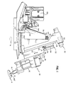
- the liquid dispensing mechanism 10 comprises a pump 12 of conventional construction which is similar to the pump used in the analyzer pump available on the analyzer from Eastman Kodak Company under the trademark "Ektachem 700".
- the pump 12 carries a disposable tip 14 on a tip support 16.
- Pump 12 includes a housing 18 to which pump 12 is connected.
- housing 18 of pump 12 comprises, as shown more clearly in Figure 4, a body 19 which has a yoke 21 extending therefrom to two lugs 23 which pivot to frame 18 at 25.
- Housing 18 reciprocates, in the direction shown by arrow 20, on a carrier 22 having opposed rails 24, 26 between which housing 18 slides.
- a position sensor flag 28 is mounted on the top of housing 18 to cooperate with sensing means 30 located at the top 32 of carrier 22. This is also shown in Figure 4.
- Carrier 22, as shown in Figure 1, is shaped to slip over a cam mechanism 50 with which carrier 22 frictionally engages.
- a slot 34 is formed in carrier 22 between rails 24, 26 to allow a cam follower 36 (shown also in Figure 5) and its idler arm 38 to project therethrough.
- Arm 38 is fixed to pump 12 or its housing 18.
- a shoulder 40 projects from pump 12 or its housing 18 to guide the pump 12 within slot 34.
- cam 50 The frictional engagement of cam 50 by carrier 22 is preferably achieved, as shown in Figures 1 and 5, by a central fixed post 52 which passes through center portion 53 of the cam.
- a compression spring 54 surrounds the post 52 and bears on end wall 56 of carrier 22.
- a retaining clip 58 holds the spring 54 in place.
- End wall 56 is apertured at 60 to accommodate post 52 which projects therethrough.
- Bottom wall 62 of cam 50 adjoins a curved sidewall 64 which is preferably provided with gear teeth 66. Most preferably, sidewall 64 at the teeth portion 66 is circular. Gear teeth 66 are positioned and shaped to engage a pinion gear 68 driven by a conventional motor 70 to cause cam 50 to rotate about the axis of post 52 in the direction shown by arrow 72.
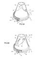
- cam track 74 which extends in three dimensions around post 52, as shown in Figures 2, 4, 5 and 6A to 6B.
- Track 74 includes a bottom-most portion 76 and all the rest of the track rises above that portion to completely encircle post 52. Because cam 50 is preferably conical in overall shape as shown in this embodiment, track 74 also traces the surface of the cone defined by this portion of cam 50.
- the uppermost portion 78 of track 74 is generally opposite to the lowermost portion 76, that is, on the opposite side of post 52 as is best shown in Figure 4.
- Cam follower 36 rides on track 74 due to gravity, except when pump carrier 22 and its cam follower are at bottom portion 76. At this time, the pump is at one of the two operative stations A or B, station B being schematically shown in Figure 1 and partially schematically in Figure 4. At either station, a top surface 80 or 80' is effective to resist further downward advance of tip 14 or pump 12. As a result, cam follower 36 is lifted off of track 74. However, to be sure that tip 14 is in fact completely seated at the station (for dispensing or aspirating, as the case may be), means are provided for biasing the cam follower downward with a predetermined positive force F indicated by arrow 82 in Figure 4. Such means preferably comprise a downwardly-directed camming surface 84, preferably V-shaped with the bottom-most portion 86 representing the complete sealing position of cam follower 36, and hence of tip 14 at either station A or B. This is shown particularly clearly in Figure 2.
- camming surface 84 In order to bias camming surface 84 downwardly, it is slidably mounted in a track 90 on face 92 of cam 50. Inside track 90, a tension spring 94 is connected at one end to surface 84, and at its opposite end 96 to cam 50.
- pump carrier 22 Because of the downward force F exerted by spring 54, indicated by arrow 100 in Figure 2, pump carrier 22 generally rotates with cam 50 as it is driven to rotate. However, means are provided, such as two limit members 110 and 112 fixed to support 114 of mechanism 10, as shown in Figures 1 and 3, to stop rotation of carrier 22 and to confine its rotation within the arc between members 110 and 112. An outwardly projecting lip 116 is formed integral with carrier 22, shown more clearly in Figure 1 and especially Figures 6A and 6B. Lip 116 is sized and positioned to abut against either limit member 110 or 112 as cam 50 rotates in the direction of arrow 118 in Figures 6A and 6B.
- tip 14 need not be replaced frequently. However, it is replaced for maintenance and cleanliness on occasion, for example, every day, and for this purpose, means are included for removably locking carrier 22 to its last known position while tip 14 is manually removed.
- Such locking means preferably comprise, as shown in Figures 1 and 5, teeth 130 molded into side edge 132 of carrier 22 adjacent lip 116.
- Cooperating with teeth 130 is a lock lever 134 actuated by a solenoid 136 to be either in a raised position, as shown, or a lowered position to engage teeth 130 to lock against relative rotation of carrier 22.
- a tension spring 138 can be used to bias lever 134 upward into its disengaged position, so that solenoid 136 need only lower lever 134.
- lever 134 is effective to hold carrier 22 in place to allow maintenance of the pump 12 and tip 14.
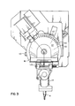
- the pump 12 is preferably pivoted upwardly about pivot 25 as shown by arrow 140 in Figure 4.
- cam 50 and its carrier is described to produce movement of tip 14 parallel to the tangent to the cone which has both a vertical and a horizontal component
- other shapes are also useful.
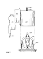
- the cam and the carrier can be cylindrical rather than conical. Parts similar to those previously described bear the same reference numeral, to which the distinguishing suffix "A" is appended.
- pump 12A supports a tip 14A for reciprocation on carrier 22A which frictionally engages cam 50A by reason of a compression spring 54A held by clip 58A as before.
- the exterior shape of cam 50A is cylindrical with track 74A being formed in the cylindrical wall of the cam.
- Carrier 22A is also cylindrical.
- the cam follower and resultant movement of pump 12A is only vertical or pivotal about post 52A, so that tip 14A lacks any horizontal component to its motion as dictated by cam 50A.
- such an analyzer features a tray 222 containing cups of serum samples 220 and disposable tips 230 which cooperate with a dispensing station 210 having a pump 240.
- Station 210 is moved by cart 248 and gear 245 through the plane marked H to first pick up a tip 230, then penetrate caps 224 of cups 220 to aspirate a patient sample, and then down into a slide block 260 and one of two entry ports 262, 264 on the block.
- Slide block 260 is part of a rotating distributor arm, not shown.
- a sloping side aperture 270 allows entry of tip 14 when slide block 260 is at station B as shown. Movement of tip 230 is of course dictated by mechanism 10 as it moves tip 14 from station A to station B. In this fashion, reference fluid is dispensed on to an ISE test element E' shown in phantom, while tip 230 dispenses a patient sample on to the same test element.
- tip 14 is preferably returned to station A where it is inserted to keep it from drying out.
- a second pump housing and pump is mounted on the carrier circumferentially spaced from the first to cooperate with the same dispensing station B.
- a second pump can be used to dispense a different liquid from the first.
- the lock lever (134 in Figure 1) is actuated to engage the teeth on the carrier.
- Slot 34 of carrier extends in a direction which is in a plane through the axis of rotation defined by post 52, that is, the slot and the post are coplanar.
- slot 34B can be non-coplanar with the axis of rotation 300, as shown in Figure 9, as long as at least a portion of it falls in and defines a plane (which extends perpendicular to the sheet of the drawing, through line 302) which intersects the axis of rotation and post 52B at some point, e.g. point X. (Parts similar to those previously described bear the same reference numerals to which the distinguishing suffix "B" is attached.) As shown the entire slot lies in such a plane since it is linear.
- the angling of slot 34B out of the plane of post 52B can be in either direction, as suggested by the alternated position 34B' shown in phantom, that is, the slot can be disposed anywhere between the position 34B and 34B'.
- the value of the angle out of the vertical is not critical, except that small angles, and particularly zero degrees, are preferred.
- the remainder of the mechanism e.g. the cam, etc., is generally the same as described above.
Applications Claiming Priority (2)
| Application Number | Priority Date | Filing Date | Title |
|---|---|---|---|
| US55669290A | 1990-07-20 | 1990-07-20 | |
| US556692 | 1990-07-20 |
Publications (2)
| Publication Number | Publication Date |
|---|---|
| EP0467471A2 true EP0467471A2 (fr) | 1992-01-22 |
| EP0467471A3 EP0467471A3 (en) | 1992-06-03 |
Family
ID=24222453
Family Applications (1)
| Application Number | Title | Priority Date | Filing Date |
|---|---|---|---|
| EP19910201864 Ceased EP0467471A3 (en) | 1990-07-20 | 1991-07-13 | Mechanism for aspirating and dispensing liquids |
Country Status (4)
| Country | Link |
|---|---|
| EP (1) | EP0467471A3 (fr) |
| KR (1) | KR920003047A (fr) |
| CA (1) | CA2041051A1 (fr) |
| IE (1) | IE912544A1 (fr) |
Cited By (2)
| Publication number | Priority date | Publication date | Assignee | Title |
|---|---|---|---|---|
| EP0525884A2 (fr) * | 1991-07-25 | 1993-02-03 | Johnson & Johnson Clinical Diagnostics, Inc. | Dispositif de verrouillage pour un poste de travail tournant |
| FR2703466A1 (fr) * | 1993-03-31 | 1994-10-07 | Anjou Rech | Dispositif de pose et de dépose d'un embout jetable à l'extrémité d'un instrument. |
Families Citing this family (1)
| Publication number | Priority date | Publication date | Assignee | Title |
|---|---|---|---|---|
| CN107621388B (zh) * | 2017-10-18 | 2024-04-12 | 深圳国技仪器有限公司 | 精确定位的湖泊采水飞行器 |
Citations (6)
| Publication number | Priority date | Publication date | Assignee | Title |
|---|---|---|---|---|
| US3049803A (en) * | 1958-01-31 | 1962-08-21 | Inv S Finance Corp | Motion transforming device and apparatus incorporating said device |
| CH464577A (de) * | 1964-04-01 | 1968-10-31 | Technicon Instr | Verfahren zur fortlaufenden Analyse flüssiger Stoffe und dafür geeignetes Probenzuführgerät |
| US3866476A (en) * | 1972-08-09 | 1975-02-18 | Rank Organisation Ltd | Analytical apparatus |
| JPS5523442A (en) * | 1978-08-09 | 1980-02-19 | Hitachi Ltd | Sampling unit |
| US4347750A (en) * | 1980-06-16 | 1982-09-07 | Eastman Kodak Company | Potentiometric metering apparatus |
| WO1989008012A1 (fr) * | 1988-02-23 | 1989-09-08 | S.O.P.A.P. S.A. | Manipulateur mecanique a axes multiples |
-
1991
- 1991-04-23 CA CA002041051A patent/CA2041051A1/fr not_active Abandoned
- 1991-07-13 EP EP19910201864 patent/EP0467471A3/en not_active Ceased
- 1991-07-18 KR KR1019910012225A patent/KR920003047A/ko active IP Right Grant
- 1991-07-19 IE IE254491A patent/IE912544A1/en unknown
Patent Citations (6)
| Publication number | Priority date | Publication date | Assignee | Title |
|---|---|---|---|---|
| US3049803A (en) * | 1958-01-31 | 1962-08-21 | Inv S Finance Corp | Motion transforming device and apparatus incorporating said device |
| CH464577A (de) * | 1964-04-01 | 1968-10-31 | Technicon Instr | Verfahren zur fortlaufenden Analyse flüssiger Stoffe und dafür geeignetes Probenzuführgerät |
| US3866476A (en) * | 1972-08-09 | 1975-02-18 | Rank Organisation Ltd | Analytical apparatus |
| JPS5523442A (en) * | 1978-08-09 | 1980-02-19 | Hitachi Ltd | Sampling unit |
| US4347750A (en) * | 1980-06-16 | 1982-09-07 | Eastman Kodak Company | Potentiometric metering apparatus |
| WO1989008012A1 (fr) * | 1988-02-23 | 1989-09-08 | S.O.P.A.P. S.A. | Manipulateur mecanique a axes multiples |
Non-Patent Citations (1)
| Title |
|---|
| PATENT ABSTRACTS OF JAPAN vol. 4, no. 051 (P-007)17 April 1980 & JP-A-55 023 442 ( HITACHI LTD. ) 19 February 1980 * |
Cited By (3)
| Publication number | Priority date | Publication date | Assignee | Title |
|---|---|---|---|---|
| EP0525884A2 (fr) * | 1991-07-25 | 1993-02-03 | Johnson & Johnson Clinical Diagnostics, Inc. | Dispositif de verrouillage pour un poste de travail tournant |
| EP0525884A3 (en) * | 1991-07-25 | 1993-06-30 | Eastman Kodak Company | Locking apparatus for a rotational work station |
| FR2703466A1 (fr) * | 1993-03-31 | 1994-10-07 | Anjou Rech | Dispositif de pose et de dépose d'un embout jetable à l'extrémité d'un instrument. |
Also Published As
| Publication number | Publication date |
|---|---|
| IE912544A1 (en) | 1992-01-29 |
| KR920003047A (ko) | 1992-02-29 |
| CA2041051A1 (fr) | 1992-01-21 |
| EP0467471A3 (en) | 1992-06-03 |
Similar Documents
| Publication | Publication Date | Title |
|---|---|---|
| US5271897A (en) | Device for raising and lowering covers of containers filled with liquid to be analyzed | |
| US4539855A (en) | Apparatus for transferring liquid out of a capped container, and analyzer utilizing same | |
| US5059393A (en) | Analysis slide positioning apparatus and method for a chemical analyzer | |
| US5132088A (en) | Automatic medical sampling device | |
| US5085832A (en) | Dispensing mechanism | |
| US4298570A (en) | Tray section for automated sample handling apparatus | |
| EP1465728B1 (fr) | Ensemble de recipients empilables d'aliquotes | |
| EP0703457A2 (fr) | Appareil d'analyse | |
| JPS62278460A (ja) | 自動分析装置 | |
| US4131426A (en) | Tip wiper apparatus and method | |
| JPH0158460B2 (fr) | ||
| EP0650589A1 (fr) | Port d'introduction de tubes a echantillon dans un analyseur chimique | |
| US7507377B2 (en) | Device for automatic analysis of a liquid sample | |
| EP1850136A1 (fr) | Dispositif mélangeur d'appareil d'analyse et analyseur comprenant un tel dispositif | |
| US5127541A (en) | Automatic medical sampling device | |
| EP0467471A2 (fr) | Mécanisme d'aspiration et de distribution des liquides | |
| EP0525884B1 (fr) | Dispositif de verrouillage pour un poste de travail tournant | |
| EP0565166A2 (fr) | Plateau pour tubes à échantillons et convoyeur magnétique | |
| US3127773A (en) | Sampling | |
| US4065973A (en) | Liquid sampler | |
| JPS6168562A (ja) | 液体試料分析装置 | |
| JPS62235570A (ja) | 試料サンプリング装置 | |
| JPS6229961Y2 (fr) | ||
| JPH0125322Y2 (fr) | ||
| JPWO2018181646A1 (ja) | 試薬容器用アダプタ |
Legal Events
| Date | Code | Title | Description |
|---|---|---|---|
| PUAI | Public reference made under article 153(3) epc to a published international application that has entered the european phase |
Free format text: ORIGINAL CODE: 0009012 |
|
| AK | Designated contracting states |
Kind code of ref document: A2 Designated state(s): BE CH DE FR GB IT LI LU NL |
|
| PUAL | Search report despatched |
Free format text: ORIGINAL CODE: 0009013 |
|
| AK | Designated contracting states |
Kind code of ref document: A3 Designated state(s): BE CH DE FR GB IT LI LU NL |
|
| 17P | Request for examination filed |
Effective date: 19920702 |
|
| 17Q | First examination report despatched |
Effective date: 19940531 |
|
| RAP1 | Party data changed (applicant data changed or rights of an application transferred) |
Owner name: CLINICAL DIAGNOSTIC SYSTEMS, INC. |
|
| RAP1 | Party data changed (applicant data changed or rights of an application transferred) |
Owner name: JOHNSON & JOHNSON CLINICAL DIAGNOSTICS, INC. |
|
| STAA | Information on the status of an ep patent application or granted ep patent |
Free format text: STATUS: THE APPLICATION HAS BEEN REFUSED |
|
| 18R | Application refused |
Effective date: 19950706 |