EP0467442A1 - Imprimante matricielle avec tête d'impression à aiguilles - Google Patents
Imprimante matricielle avec tête d'impression à aiguilles Download PDFInfo
- Publication number
- EP0467442A1 EP0467442A1 EP91201733A EP91201733A EP0467442A1 EP 0467442 A1 EP0467442 A1 EP 0467442A1 EP 91201733 A EP91201733 A EP 91201733A EP 91201733 A EP91201733 A EP 91201733A EP 0467442 A1 EP0467442 A1 EP 0467442A1
- Authority
- EP
- European Patent Office
- Prior art keywords
- matrix printer
- printing
- carrier
- spring
- printer according
- Prior art date
- Legal status (The legal status is an assumption and is not a legal conclusion. Google has not performed a legal analysis and makes no representation as to the accuracy of the status listed.)
- Withdrawn
Links
Images


Classifications
-
- B—PERFORMING OPERATIONS; TRANSPORTING
- B41—PRINTING; LINING MACHINES; TYPEWRITERS; STAMPS
- B41J—TYPEWRITERS; SELECTIVE PRINTING MECHANISMS, i.e. MECHANISMS PRINTING OTHERWISE THAN FROM A FORME; CORRECTION OF TYPOGRAPHICAL ERRORS
- B41J2/00—Typewriters or selective printing mechanisms characterised by the printing or marking process for which they are designed
- B41J2/22—Typewriters or selective printing mechanisms characterised by the printing or marking process for which they are designed characterised by selective application of impact or pressure on a printing material or impression-transfer material
- B41J2/23—Typewriters or selective printing mechanisms characterised by the printing or marking process for which they are designed characterised by selective application of impact or pressure on a printing material or impression-transfer material using print wires
- B41J2/27—Actuators for print wires
- B41J2/275—Actuators for print wires of clapper type
Definitions
- the invention relates to a matrix printer with a print head carrying printing needles, wherein each printing needle can be actuated by means of a rotating arm, which rotating arm is connected to a spring which determines an axis of rotation of the rotating arm and forms a fastening bridge between the rotating arm and a carrier.
- Such a matrix printer is known from US-PS 45 85 361.
- the rotary arm is connected at one end to a first leg of a U-shaped yoke by a leaf spring.
- the center of the rotating arm lies at a short distance from a second leg of the yoke, around which an excitation coil is attached.
- the rotating arm is pulled against the second leg of the yoke, and the printing needle attached to the other end of the rotating arm moves in the direction of the printing plane and produces the desired impression on the printing medium.
- the leaf spring is preloaded by tightening the rotating arm.
- the invention has for its object to improve a matrix printer of the type mentioned with regard to the printing frequency and the constancy of the printing force over the entire frequency range.
- the matrix printer should be able, for example, at any frequency up to 3 kHz and a constant pressure force, the z. B. for an original and at least five copies must be sufficient to achieve an impression.
- This object is achieved according to the invention in a printhead of the type mentioned in that the center of mass of the rotating arm and the axis of rotation lie in one and the same plane, which plane is transverse to the printing plane. After a rebound, vibrations no longer occur in the direction transverse to the pressure plane.
- the center of gravity of the swivel arm should be calculated from the mass of the swivel arm and all masses connected to the swivel arm, e.g. B. the mass of the pressure needle and possibly the mass of the anchor.
- the center of mass of the rotary arm is preferably as close as possible to the axis of rotation. This has the advantage that no translational vibrations of the rotating arm occur due to rebound.
- the axis of rotation is determined by a weakening of a leaf spring, the central plane of which runs parallel to the broad side and lies in the plane mentioned.
- Such leaf springs are simple in shape and are relatively easy to manufacture.
- the spring is a cross spring, the cross line of which coincides approximately with the axis of rotation.
- Cross springs have the advantage that relatively high mechanical loads are possible.
- US-PS 41 36 978 from which a matrix printer with a cross spring has become known.
- This cross spring like the leaf spring from the patent mentioned at the beginning, is located at the end of the rotary arm and therefore has the same disadvantages.
- two leaf springs belonging to two different cross springs are connected to one another by a U-shaped bridge, the U-shaped bridges being interleaved and connected to the carrier.
- This cross springs are easy to manufacture in this way.
- each rotary arm is designed as a two-armed rotary lever and is attached to the carrier at a distance via the spring and that the armature is attached to one and the pressure needle to the other free lever end, the armature being attracted by non-energized coils by permanent magnetic forces against the spring force and can be moved to actuate the needles when excited.
- This design enables simple and automatic manufacture of the rotary lever with the anchors or pressure needles provided at the free ends.
- the rotary arms are attached to the carrier in a star shape with their radially outer armatures and that the magnet systems arranged in a ring on the outer circumference of a housing each lie in a radial plane and each have a coil with a core, a yoke, a permanent magnet and have a pole piece, each Weil forms a corner area with the core, in which the associated, rectangular-shaped anchor engages with the formation of air gaps.
- the magnet systems can, for example, be cast in the housing with a special sealing compound.
- the magnet systems each in its own radial plane, form a self-contained permanent and electromagnetic circuit for actuating the associated pressure needle attached to the rotating arm.
- each armature is rectangular and has two functional surfaces, one of which forms a working air gap with a functional surface of the core and the other forms a secondary air gap with a functional surface of the pole piece, which maintains a minimum size in any operating position.
- This minimum size on the one hand hinders the flow as little as possible, on the other hand it prevents the anchor from sticking.
- the ratio between the cross-sectional area of the permanent magnet and the size of one of the functional areas in the working air gap is advantageously chosen such that the magnetic flux is compressed in the adjacent iron parts until shortly before magnetic saturation. This results in a large mechanical force for armature actuation with minimal energy consumption.
- the iron path of a magnetic circuit is at least partially, e.g. formed as a laminate in the area of the core enclosed by the coil. This means that if the magnetic field changes in the yoke, there are fewer cyclone losses.
- the modular design of the magnet and mechanical assembly enables simple replacement without rework and adjustment.
- the pressure needles attached to the star-shaped rotating levers run centrally in the direction of the axis of the housing.
- the printing needles are advantageously guided by support plates which are rotatably arranged in a needle carrier.
- the needle carrier forms a structural unit for itself and is e.g. Connected to the carrier via locking hooks. Due to the rotatable arrangement of the support plates, jamming of the printing needles is avoided if the switching head of the matrix printer e.g. is rotatably arranged.
- the support plates are preferably made of steel and provided with a wear-resistant layer. The support length of the printing needles limited by the support plates is selected such that the natural frequency of the individual sections is greater than the maximum printing frequency.
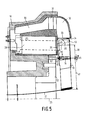
- the printhead 1 of a matrix printer (not shown further) has a housing 10 with a circular cross section for receiving magnet systems 11 arranged in a ring on its outer circumference are.
- the attachment takes place via leaf springs 14, the ends of which are fastened on the one hand in recesses 15 of the carrier 12 (FIG. 6) and on the other hand in recesses 16 (FIG. 3a) of the rotary arms 13 by laser welding.
- the leaf springs 14 have a weakening 17 in their central region, which determines an axis of rotation 18 of the rotating arm 13.
- angular armatures 19 are fastened, which have two functional surfaces 20, 21 and, in the assembled state, interact with the magnet systems 11 described below.
- printing needles 22 are attached, which are directed along an axis 23 of the print head 1.
- the Drehach se 18 and the center of mass M of the rotary arm 13 and all masses connected to the rotary arm 13 lie in a plane E which is transverse to the pressure plane DE.
- 24 denotes a printing roller, 25 a printing medium (for example paper) and 26 a printing nip between the printing head 1 and the printing medium 25.
- a printing medium for example paper
- the magnet systems 11 each contain an excitation coil 27, a first yoke part 28 in the excitation coil 27 with a functional surface 29, a second yoke part 30 outside the excitation coil 27, a permanent magnet 31 and a pole piece 32 with a functional surface 33.
- the functional surfaces 20 and 33 lie opposite each other at a distance and form a secondary air gap 34 (FIGS. 5 and 6).
- Permanent magnets made of SmCo5 with 225 KA / m are preferably used for the permanent magnets 31.
- the rotating arms 13 are box-shaped for reasons of strength.
- the angular anchors 19 are firmly connected to the outer free ends of the rotating arms by laser welding.
- a sleeve 13a for receiving the printing needles 22 is attached.
- the printing needles 22 are pushed into the sleeves 13a, and the printing needles 22, the sleeves 13a and the rotating arms 13 are e.g. B. connected by soldering.
- Such sleeves enable simpler connection technology.
- a pressure needle 22, a sleeve 13a and a rotating arm 13 in the manner described below.
- the sleeve 13a is pushed into the rotary arm 13 and the pressure needle 22 into the sleeve 13a.
- the three parts 13, 13a, 22 are connected to one another by laser welding.
- Glue is introduced on the lower side of the rotary arm 13 by means of capillary action between the rotary arm 13 and the sleeve 13a on the one hand and between the sleeve 13a and the pressure needle 22 on the other hand.
- the glue dampens vibrations of the printing needle.
- FIGS. 4a and 4b show a perspective view of another rotary arm 35 according to the invention, the same numbers being used for the parts corresponding to FIGS. 1 to 3.
- the rotary arm 35 comprises two cross springs 36, 37.
- Each cross spring has two leaf spring elements 38, 39; 40, 41, two leaf spring elements 38, 40 and 39, 41 belonging to different cross springs being connected to each other by a U-shaped bridge 42, 43.
- the U-shaped bridges 42, 43 are interleaved and connected to the carrier 12.
- the center of gravity M of the rotary arm 35 lies on the axis of rotation 18, so that no translational vibrations occur during the impact.
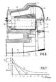
- 5 shows the print head 1 with the excitation coil 27 not excited, and FIG.
- FIG. 6 shows the print head with the excitation coil 27 excited, with the working air gap 44 and secondary air gap 34 not drawn to scale first yoke part 28, wherein the leaf spring 14 is biased.
- a movement of the pressure needle 22 in the direction of the pressure medium is generated in that the magnetic field of the permanent magnet 31 is weakened by excitation of the excitation coil until the bias of the leaf spring 14 is greater than the holding force of the permanent magnet 31.
- the printing needle 22 moves in the direction of the printing plane DE and generates the desired impression on the printing medium 25.
- the partial levers formed by the axis of rotation 18 are designated by 46 and 47 in FIG. 5.
- the ratio of the lengths of the partial levers 46, 47 is approximately 1: 3.
- a needle carrier is designated, the Has support plates 49 for guiding the printing needles 22.
- a rotatable switching head 50 with a guide block 51 for the printing needles 22 sits on the needle carrier 48.
Landscapes
- Impact Printers (AREA)
Applications Claiming Priority (6)
| Application Number | Priority Date | Filing Date | Title |
|---|---|---|---|
| DE4022355 | 1990-07-13 | ||
| DE4022353 | 1990-07-13 | ||
| DE4022353 | 1990-07-13 | ||
| DE4022355 | 1990-07-13 | ||
| DE4106921 | 1991-03-05 | ||
| DE19914106921 DE4106921A1 (de) | 1991-03-05 | 1991-03-05 | Matrixdrucker mit einem drucknadeln tragenden druckkopf |
Publications (1)
| Publication Number | Publication Date |
|---|---|
| EP0467442A1 true EP0467442A1 (fr) | 1992-01-22 |
Family
ID=27201456
Family Applications (1)
| Application Number | Title | Priority Date | Filing Date |
|---|---|---|---|
| EP91201733A Withdrawn EP0467442A1 (fr) | 1990-07-13 | 1991-07-04 | Imprimante matricielle avec tête d'impression à aiguilles |
Country Status (2)
| Country | Link |
|---|---|
| EP (1) | EP0467442A1 (fr) |
| JP (1) | JPH04232760A (fr) |
Citations (6)
| Publication number | Priority date | Publication date | Assignee | Title |
|---|---|---|---|---|
| JPS59158266A (ja) * | 1983-02-28 | 1984-09-07 | Matsushita Electric Works Ltd | ドツトプリンタ用電磁石装置 |
| JPS60187563A (ja) * | 1984-03-07 | 1985-09-25 | Tokyo Electric Co Ltd | ドツトプリンタヘツド |
| US4624589A (en) * | 1984-03-15 | 1986-11-25 | Tokyo Electric Co., Ltd. | Dot printer head |
| US4626115A (en) * | 1984-03-08 | 1986-12-02 | Tokyo Electric Co., Ltd. | Dot printer head |
| US4840501A (en) * | 1986-04-29 | 1989-06-20 | Dataproducts Corporation | Three pole printhead actuator |
| EP0338176A1 (fr) * | 1988-04-22 | 1989-10-25 | MANNESMANN Aktiengesellschaft | Tête d'impression pour imprimante matricielle à aiguilles |
-
1991
- 1991-07-04 EP EP91201733A patent/EP0467442A1/fr not_active Withdrawn
- 1991-07-12 JP JP19738191A patent/JPH04232760A/ja active Pending
Patent Citations (6)
| Publication number | Priority date | Publication date | Assignee | Title |
|---|---|---|---|---|
| JPS59158266A (ja) * | 1983-02-28 | 1984-09-07 | Matsushita Electric Works Ltd | ドツトプリンタ用電磁石装置 |
| JPS60187563A (ja) * | 1984-03-07 | 1985-09-25 | Tokyo Electric Co Ltd | ドツトプリンタヘツド |
| US4626115A (en) * | 1984-03-08 | 1986-12-02 | Tokyo Electric Co., Ltd. | Dot printer head |
| US4624589A (en) * | 1984-03-15 | 1986-11-25 | Tokyo Electric Co., Ltd. | Dot printer head |
| US4840501A (en) * | 1986-04-29 | 1989-06-20 | Dataproducts Corporation | Three pole printhead actuator |
| EP0338176A1 (fr) * | 1988-04-22 | 1989-10-25 | MANNESMANN Aktiengesellschaft | Tête d'impression pour imprimante matricielle à aiguilles |
Non-Patent Citations (2)
| Title |
|---|
| PATENT ABSTRACTS OF JAPAN, vol. 10, no. 33 (M-452) 8. Februar 1986; & JP-A-60 187 563 (TAKASHI) 25. September 1985 * |
| PATENT ABSTRACTS OF JAPAN, vol. 9, no. 7 (M-350) 12. Januar 1985; & JP-A-59 158 266 (OKADA) 7. September 1984 * |
Also Published As
| Publication number | Publication date |
|---|---|
| JPH04232760A (ja) | 1992-08-21 |
Similar Documents
| Publication | Publication Date | Title |
|---|---|---|
| DE2636985C3 (de) | Tauchankermagnet, sowie dessen Verwendung in einem Drahtmatrixdrucker | |
| DE3400264C2 (fr) | ||
| EP2486575B1 (fr) | Actionneur pour moteur à combustion interne | |
| EP0060969A1 (fr) | Système d'entraînement magnétique pour produire des mouvements linéaires | |
| EP0078324A1 (fr) | Relais electromagnetique polarise | |
| WO1990003037A1 (fr) | Aimant a noyau plongeur et son utilisation comme marteau d'impression dans un dispositif a marteau d'impression | |
| DE3135957C2 (fr) | ||
| DE2133931C3 (de) | Magnetsystem für Relais | |
| DE19751609B4 (de) | Schmalbauender elektromagnetischer Aktuator | |
| WO2012041550A1 (fr) | Actionneur | |
| DE2503159B2 (fr) | ||
| DE2135821A1 (de) | Reibungsvorrichtung | |
| WO1988008792A1 (fr) | Tetes d'imprimante a aiguilles avec aimants a armatures battantes | |
| DE2632126C2 (de) | Polarisiertes Miniaturrelais | |
| EP3011571B1 (fr) | Aimant de maintien présentant une puissance d'excitation électrique particulièrement faible | |
| DE3635894A1 (de) | Stossdaempfer | |
| DE19720858A1 (de) | Elektromagnetische Betätigungsvorrichtung | |
| EP0028314B1 (fr) | Dispositif de déclenchement électromagnétique, en particulier pour l'actionnement de marteaux d'impression | |
| DE4334031A1 (de) | Bistabiler Hubmagnet | |
| EP0935054A2 (fr) | Vérin électromagnétique | |
| DE68906612T2 (de) | Kraftmotor. | |
| EP0467442A1 (fr) | Imprimante matricielle avec tête d'impression à aiguilles | |
| DE3400888A1 (de) | Druckstiftbetaetigungsvorrichtung fuer punktmatrixdrucker und verfahren zu ihrer herstellung | |
| EP0073002B1 (fr) | Déclencheur électromagnétique | |
| EP0216943A1 (fr) | Dispositif d'actionnement électromagnétique notamment de marteaux d'impression |
Legal Events
| Date | Code | Title | Description |
|---|---|---|---|
| PUAI | Public reference made under article 153(3) epc to a published international application that has entered the european phase |
Free format text: ORIGINAL CODE: 0009012 |
|
| AK | Designated contracting states |
Kind code of ref document: A1 Designated state(s): DE FR GB IT SE |
|
| 17P | Request for examination filed |
Effective date: 19920722 |
|
| 17Q | First examination report despatched |
Effective date: 19931029 |
|
| STAA | Information on the status of an ep patent application or granted ep patent |
Free format text: STATUS: THE APPLICATION IS DEEMED TO BE WITHDRAWN |
|
| 18D | Application deemed to be withdrawn |
Effective date: 19940201 |